Independent Research Project
AIM: To perform a fluid-surface interaction simulation for a practical problem using ANSYS FLUENT.
THEORY:
FLUID SURFACE INTERACTION
Fluid-structure interaction (FSI) is the multiphysics study of how fluids and structures interact. The fluid flow may exert pressure and/or thermal loads on the structure. These loads may cause structural deformation significant enough to change the fluid flow itself. Undesired effects in your product may increase as the level of the fluid-structure interaction increases. With ANSYS simulation you can gain a deeper understanding of the phenomena occurring with your product to ensure safety, reliability and longevity.
ANSYS has a range of solutions for all the fluid-structure interaction challenges one may face to provide the level of fidelity needed. Simple fluid-structure interaction problems can be solved completely within ANSYS CFD. This is known as rigid body motion, exemplified by an impeller rotating in a mixing tank.
As the fluid-structure interaction increases and the problem needs more detailed evaluation, ANSYS has an automated, easy-to use-solution called one-way coupling. One-way coupling solves the initial CFD or ANSYS Mechanical simulation and automatically transfers and maps the data to the other system. An example of this would be simulating the fluid flow around a cone flow meter and automatically transferring this data to calculate the resulting structural response.
For the most complex and tightly coupled fluid-structure interaction problems, you can use System Coupling to perform two-way coupled FSI simulations. The fluid and structural simulations are both set up and solved at the same time. While being solved, data is automatically transferred between the two solvers to achieve robust and accurate results. An example of this would be calculating flow around a rigid airplane wing and transferring the pressure loads to solve structural deformation. The structural deformation would be transferred back to the CFD simulation to calculate the flow again, and this process would repeat.
Think of a wind gust rotating a turbine blade, a boat hull under wavy conditions, or the air rushing over the front panel of an F1 car. Anywhere a fluid and structure meet, FSI occurs.
Understanding FSI is critical for the design of many products. Not accounting for the effect of a fluid on a solid or vice versa can result in overestimating or underestimating product performance. Consequently, the end product design may lead to unexpected and undesirable outcomes, ranging from bothersome noises to complete product failure.
Whether you're designing a bridge, aircraft, or gas turbine, understanding how the interaction of fluids and structures impacts your project requires a solution that accurately predicts and integrates both behaviors.
APPLICATIONS OF FSI
Designing aircraft: As a plane flies, airflow around the wing causes the wing to deform (which, in turn, changes the way the air flows, altering the wing even more). Solving the FSI in wing design dramatically increases the aerodynamic performance of the aircraft.
Modeling blood flow: To evaluate the effects of blocked blood vessels in aneurysms, FSI accounts for how blood pressure and flow velocity influence a vessel’s ability to stretch and change in size.
Predicting sound: When air flows pass over a car, surfaces like the hood and side mirrors can vibrate and radiate sound into the interior. By addressing these FSIs, engineers can adjust the design to reduce noise and increase passenger comfort.
PROCEDURE:
CREATING GEOMETRY
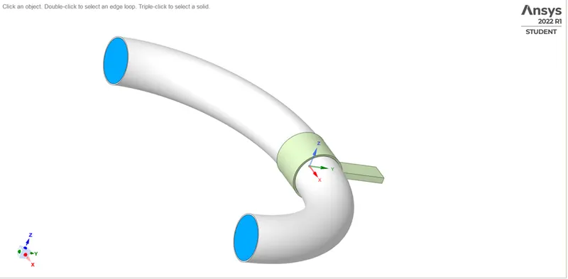
Draw a horizontal line from origin of about 50mm and then from its end draw a vertical construction line of about 350mm then use the sweep arc tool to create the arc between these points. Once that is done mirror the lines along the y-axis, then use the cylinder tool to create a 3D cylinder from the lines and then copy paste the cylinder surface to create the pipe and use pull tool on it to pull it about 0.11inches. create the anchor on the bent of the pipe and then color the parts as per the problem and name them accordingly.
SETTIUNG-UP TRANSATIONAL STRUCTRAL
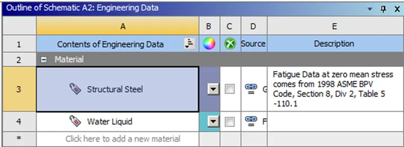
First we add liquid water in the engineering data
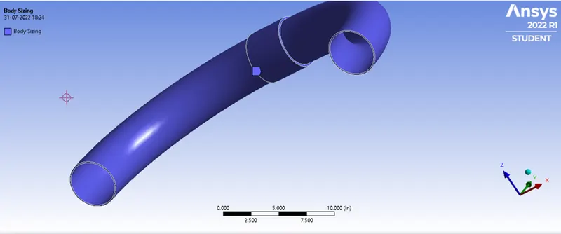
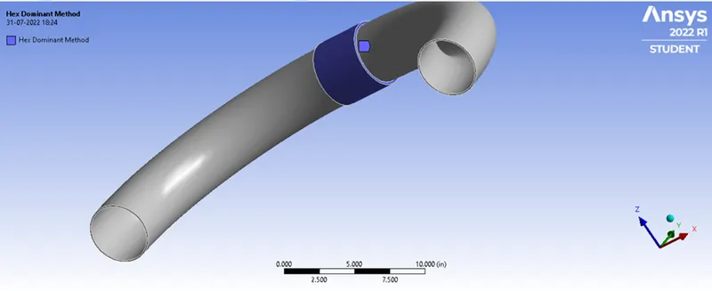
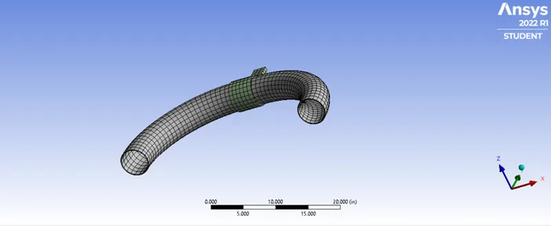
After this the model is setup where water is suppressed as it won’t be included in transient analysis. After that we mesh the geometry by using body sizing and method.
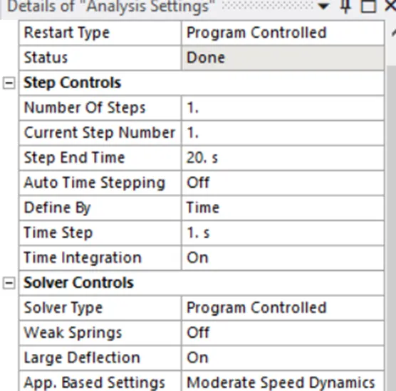
After this the analysis settings were set as following
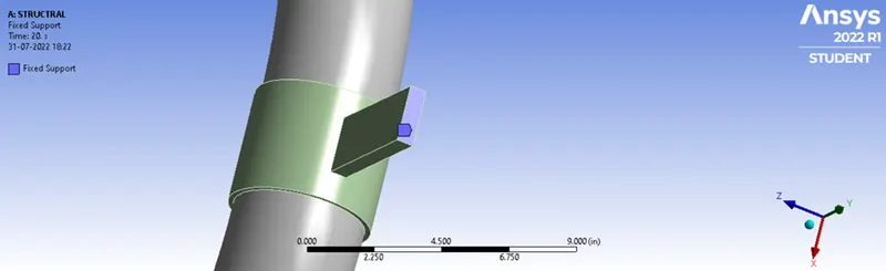
After this fixed support was added at the shown position
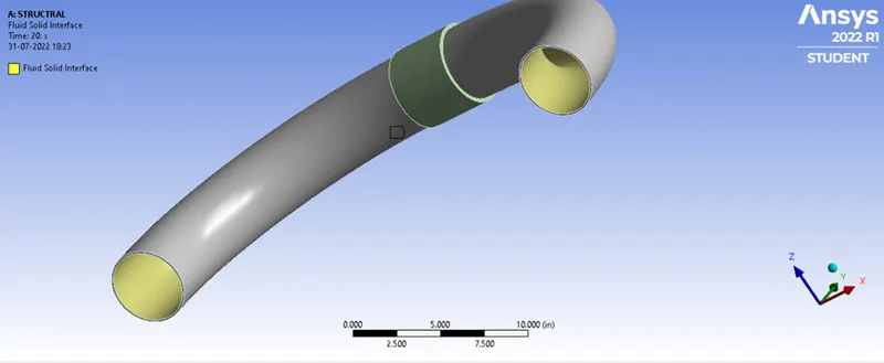
After this we added fluid-solid interaction in the analysis setup for the inner surface of the pipe
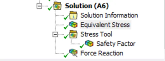
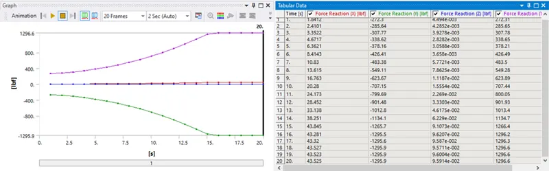
Now the following points were calculated using the solutions in transient structural settings
SETTING-UP FLUENT CASE
We connect the transitional geometry to fluent geometry and use the fluent mesher to mesh the geometry,
Sizing and Inflation layers were used to mesh the geometry and, pipe and anchor were suppressed for physics
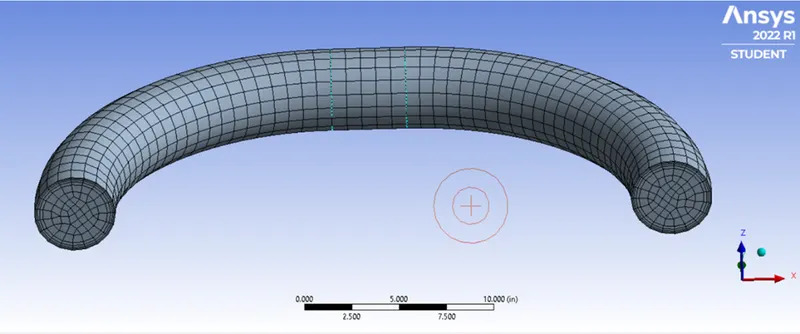
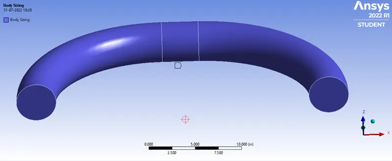
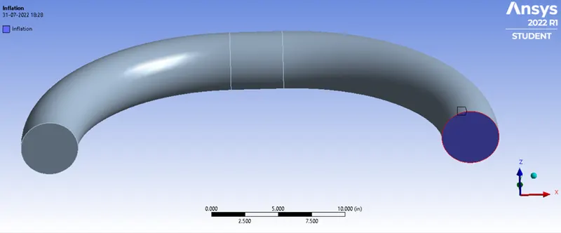
After meshing the named selections were done accordingly.
Then we setup the case in fluent
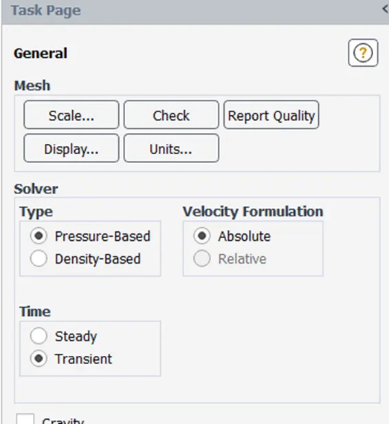
The time was set to be transient but before that mesh was checked for errors
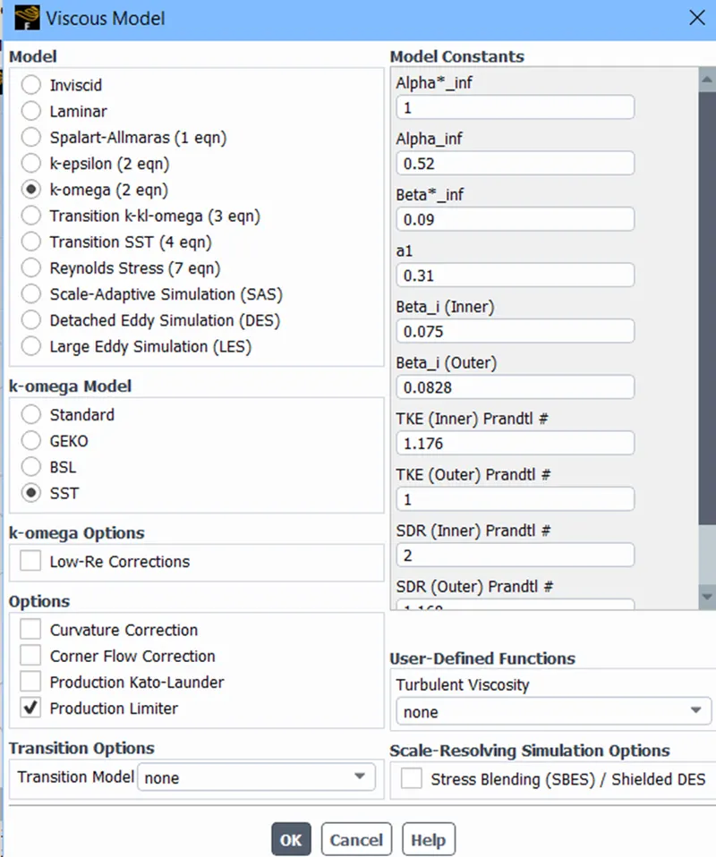
Then in viscous model setting turbulence model was setup as K-omega SST.
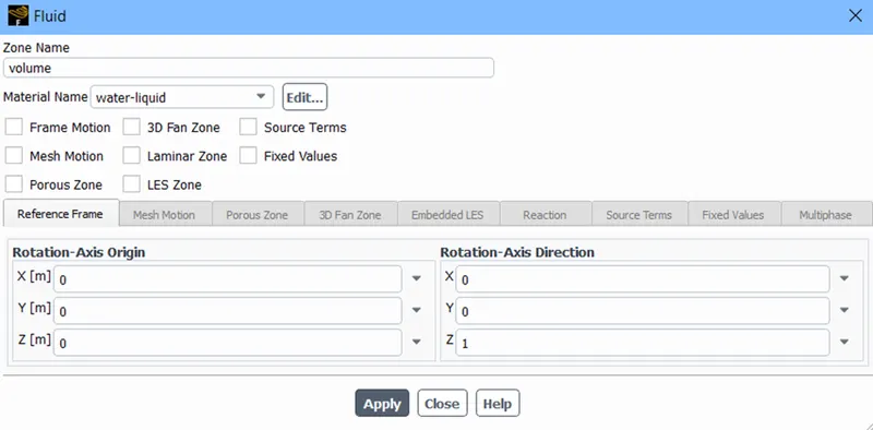
After this in cell zone settings for volume cell zone material was set to be water
The boundary conditions were set as following
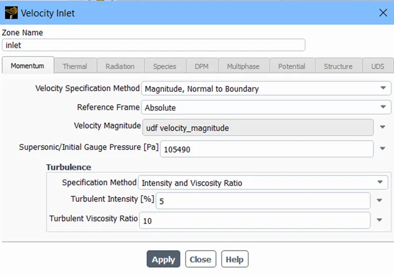
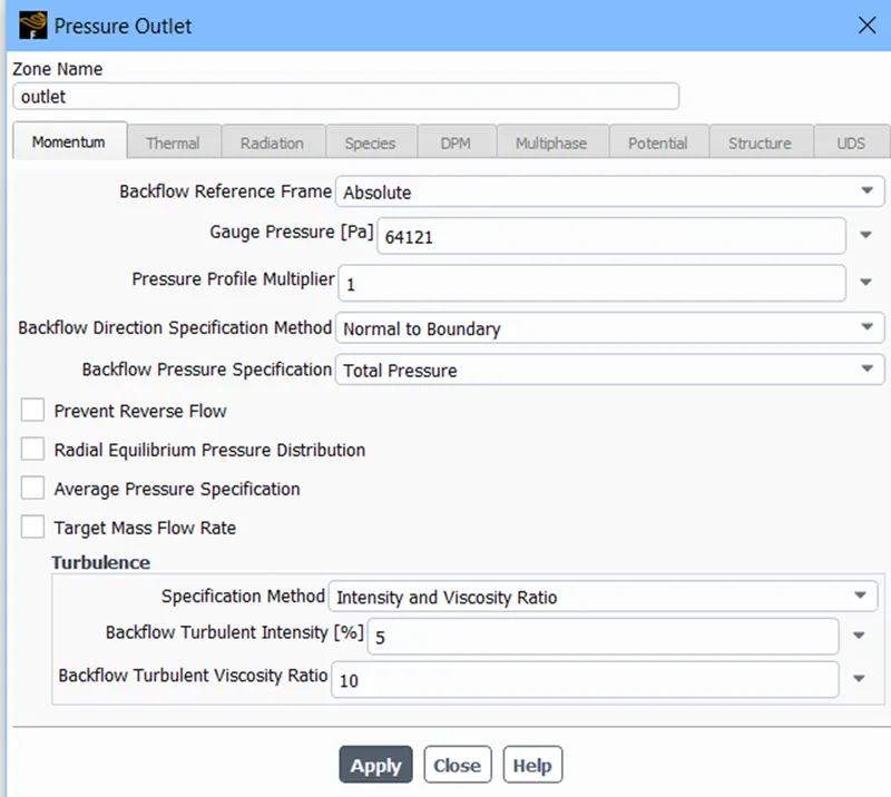
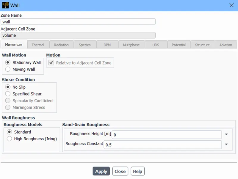
For velocity profile at inlet a UDF was used by interpreting the created function code using the user-defined settings.
#include "udf.h"
DEFINE_PROFILE(velocity_magnitude, t, i)
{
	real default_early_velocity_mag,default_late_velocity_mag,velocity_mag;

	real ramp_start,ramp_end;
	real the_current_time = CURRENT_TIME;
	face_t f;

	default_early_velocity_mag=0.0;
	default_late_velocity_mag=15.24;
	ramp_start=0.0;
	ramp_end=15.24;

	velocity_mag=default_early_velocity_mag;

	if ((the_current_time>=ramp_start) && (the_current_time<=ramp_end))
	{
		velocity_mag=the_current_time;
	}

	if ((the_current_time>ramp_end))
	{
		velocity_mag=default_late_velocity_mag;
	}

	begin_f_loop(f,t)
		{
			F_PROFILE(f,t,i) = velocity_mag;
		}
	end_f_loop(f,t)
}
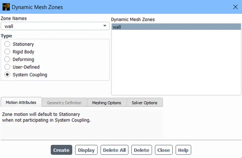
After this the dynamic mesh was enabled for wall and it was set at system coupling.
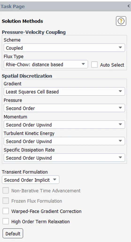
The solution method were set as following
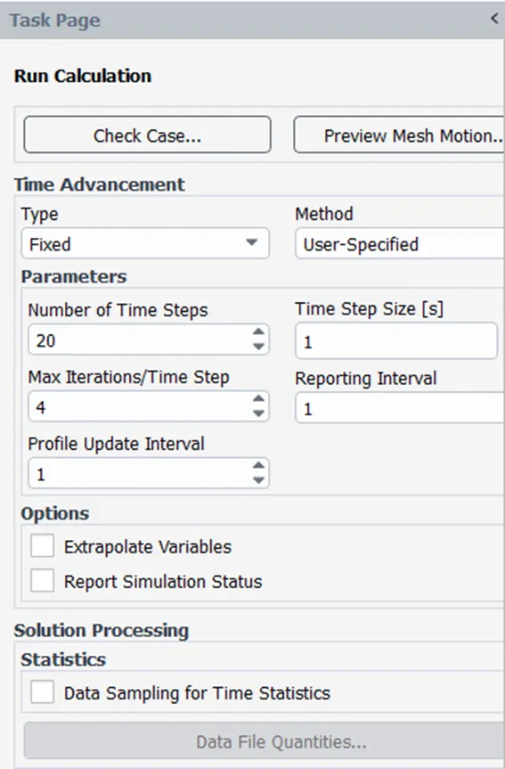
After this the setup was initialised in hybrid mode and run calculations setting was set as following
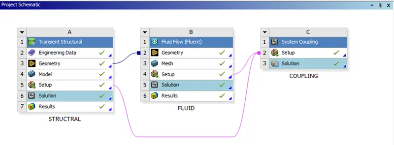
In workbench both structural and fluent analysis were couped using system coupling and the connections were setup as following
After this in system coupling setup data transfer between fluid and structural was set in two ways one from fluid to structural and second from structural to fluid.
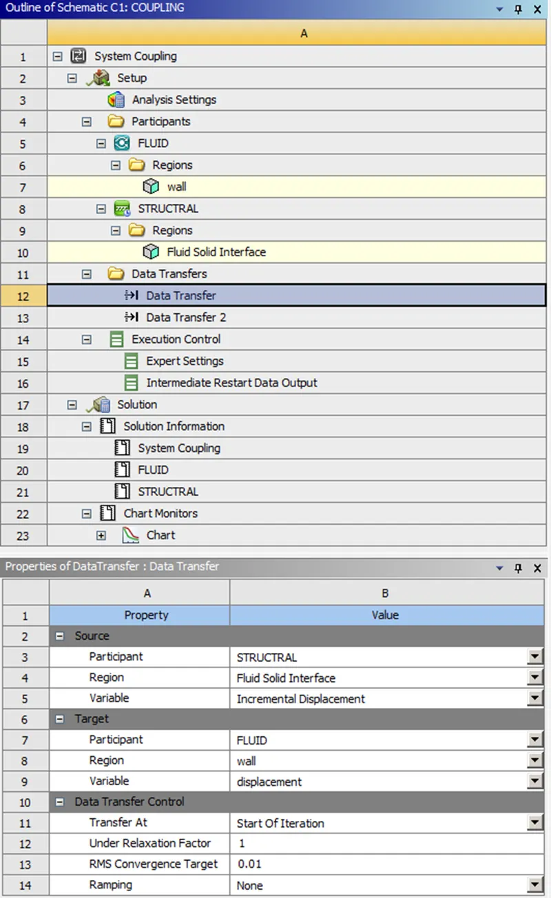
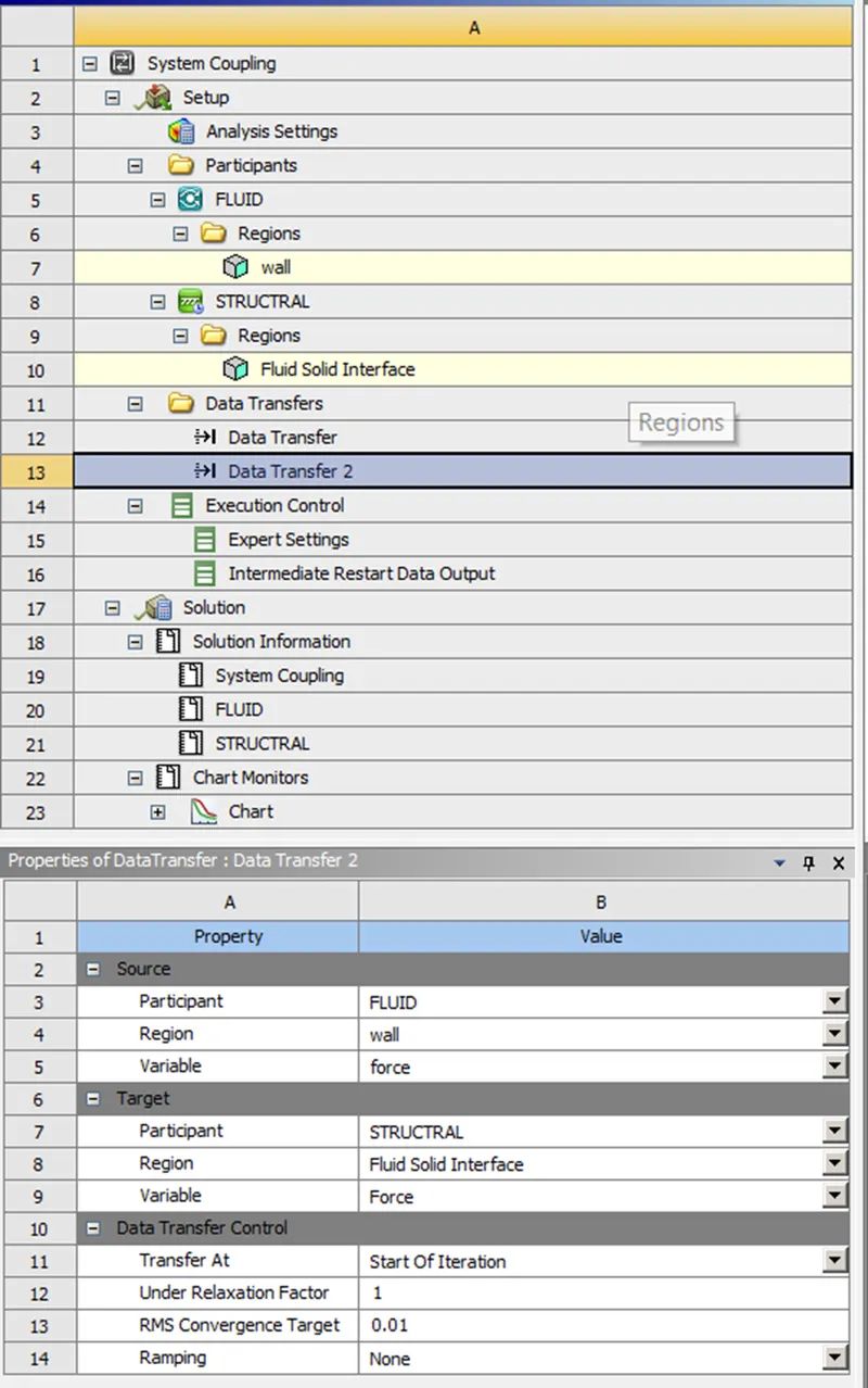
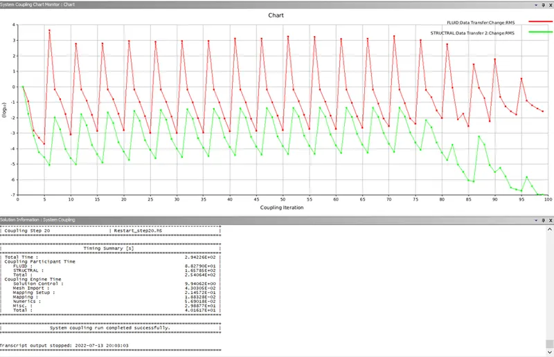
After this the solution was performed in the system coupling window and both the setups were run together by system coupling.
RESULTS:
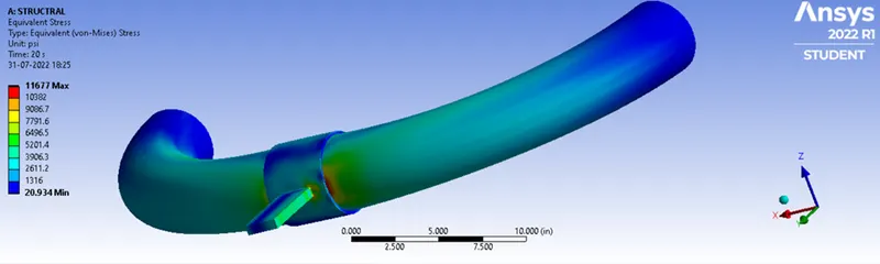
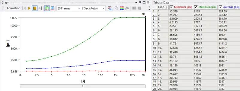
EQUIVALENT STRESS
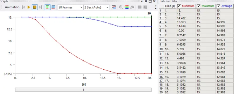
FACTOR OF SAFETY

FORCE REACTION

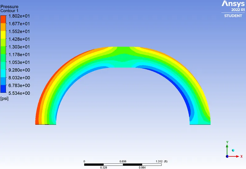
PRESSURE CONTOUR
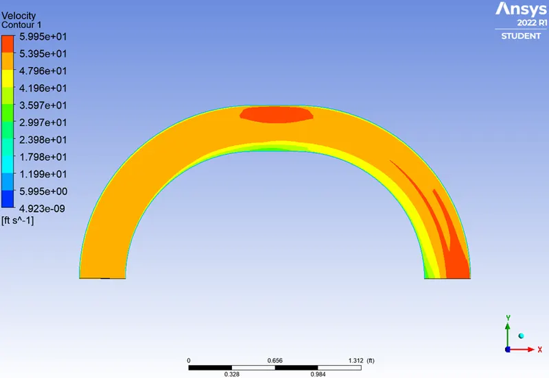
VELOCITY CONTOUR
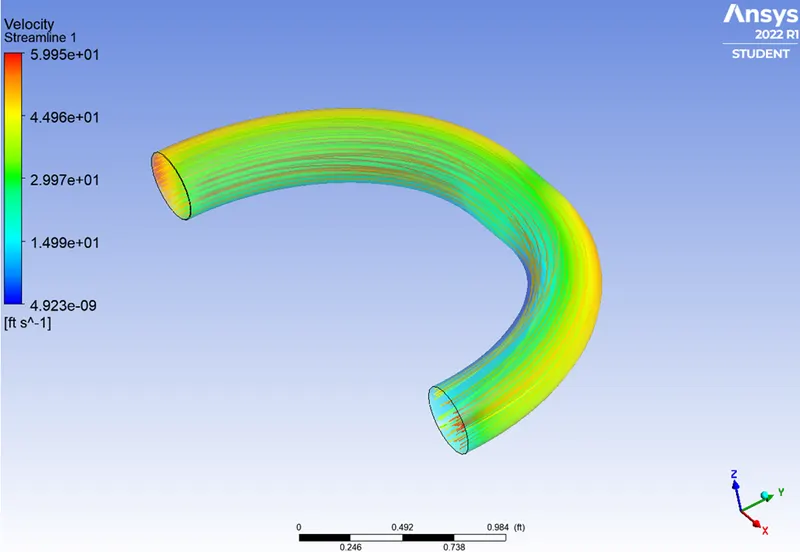
VELOCITY STREAMLINE
CONCLUSION: We were able to successfully setup the Fluid-Structure Interaction simulation for a practical problem of flow through a 180degree bent pipe. The results obtained were 98% accurate when compared to that of hand calculations. FSI allows us to understand better the interaction between fluid and solid which helps in creation of better geometry for solids and improvised structures.