Independent Research Project
Simulation of a Single Cylinder Internal Combustion Engine Piston
Objective:
- To simulate the motion of an internal combustion engine piston during a uniform angular acceleration of the crankshaft.
- To reveal the stresses and strains developed in the assembly along with the time variational plots of the relative displacement, the relative velocity and the relative acceleration of the piston.
Motivation:
- With the help of this project, the mechanical design of an internal combustion engine could be optimized for a particular maximum acceleration of the vehicle.
- The time variational plots would reveal the complete kinematics of the piston.
Geometry Information:
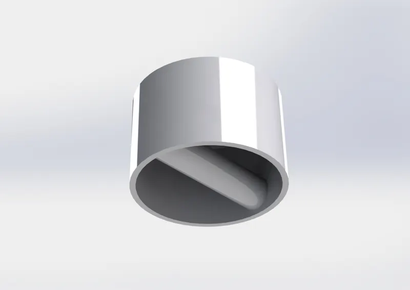
- Piston:
- Outer diameter 65 mm
- Inner diameter 60 mm
- Roof thickness 2.5 mm
- Height 42.5 mm (external)
- Bar diameter 15 mm
- Bar center distance from bottom 10 mm
- Image:
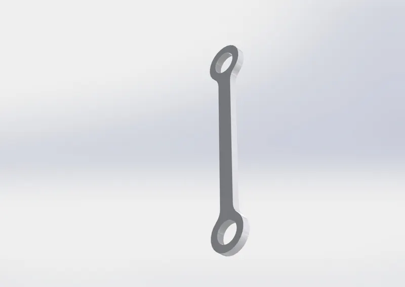
- Rod:
- Inner diameter 15 mm
- Outer diameter 25 mm
- Thickness 5 mm
- Height 147.91 mm (end-to-end)
- Image:
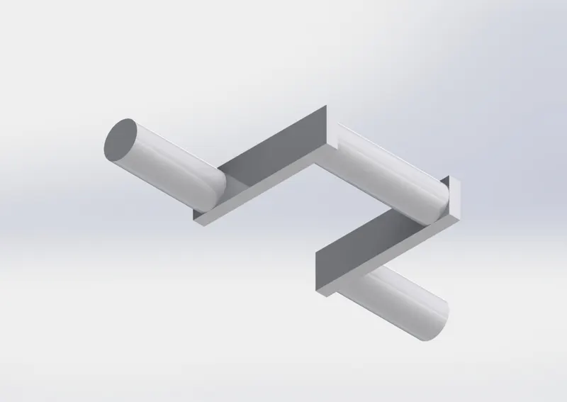
- Crankshaft:
- Bar diameter 15 mm
- Central bar length 50 mm
- Side bar length 40 mm
- Plate length 60 mm
- Plate thickness 5 mm
- Image:
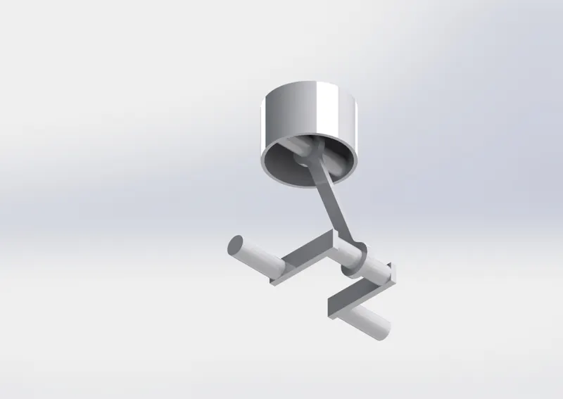
- Assembly:
Procedure:
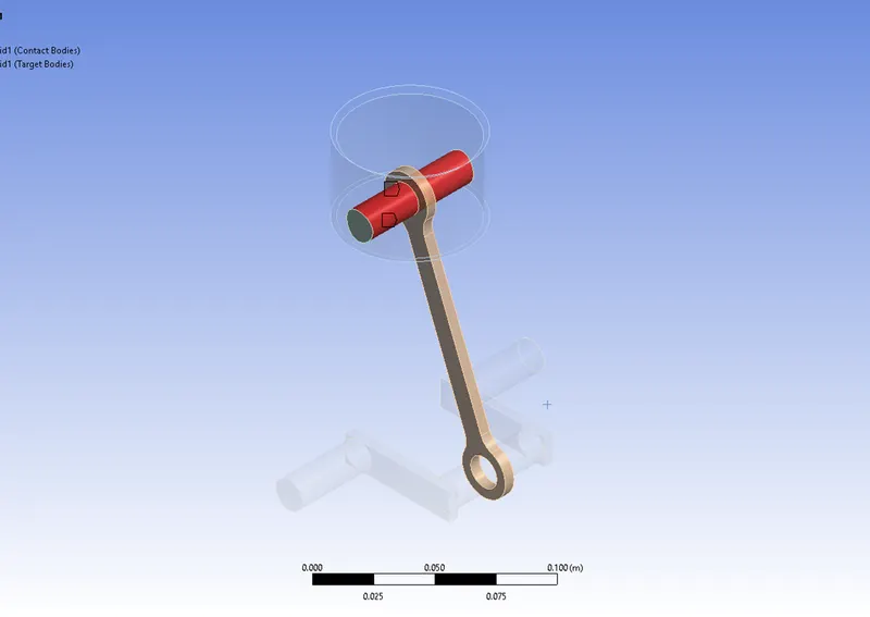
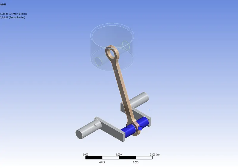
- Contacts:
- Piston to Rod Contact:
- Contact: Piston
- Target: Rod
- Type: Frictionless
- Formulation: Augmented Lagrange
- Interface Treatment: No Offset, No Ramping
- Other Settings: Default
- Image:
- Rod to Crankshaft Contact:
- Contact: Rod
- Target: Crankshaft
- Type: Frictionless
- Formulation: Augmented Lagrange
- Interface Treatment: No Offset, No Ramping
- Other Settings: Default
- Image:
- Piston to Rod Contact:
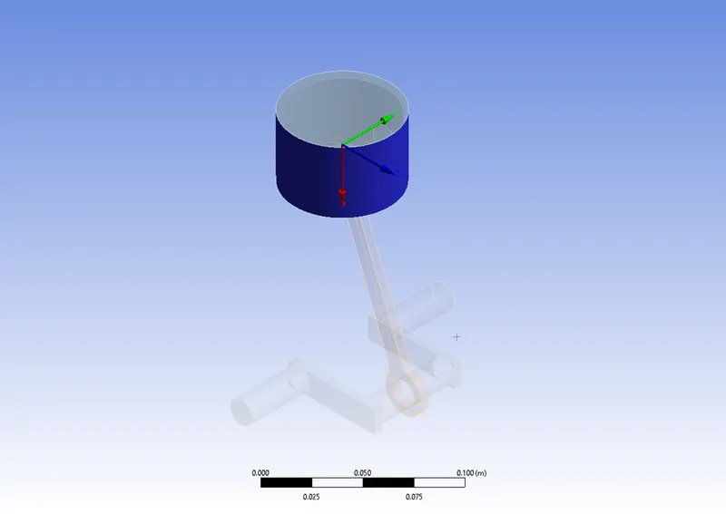
- Joints:
- Ground to Piston Joint:
- Connection Type: Body-Ground
- Type: Translational
- Reference: Ground
- Mobile: Piston
- Degree of Freedom: X
- Other Settings: Default
- Image:
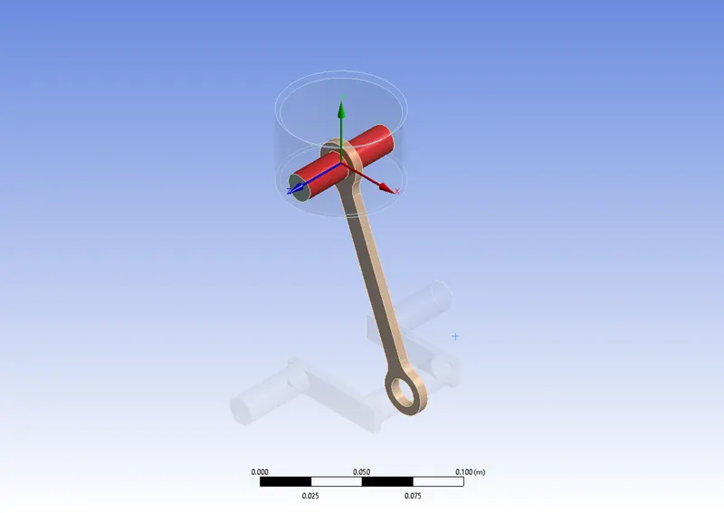
- Piston to Rod Joint:
- Connection Type: Body-Body
- Type: Cylindrical
- Reference: Piston
- Mobile: Rod
- Degrees of Freedom: Z, RZ
- Other Settings: Default
- Image:
- Rod to Crankshaft Joint:
- Connection Type: Body-Body
- Type: Cylindrical
- Reference: Rod
- Mobile: Crankshaft
- Degrees of Freedom: Z, RZ
- Other Settings: Default
- Image:
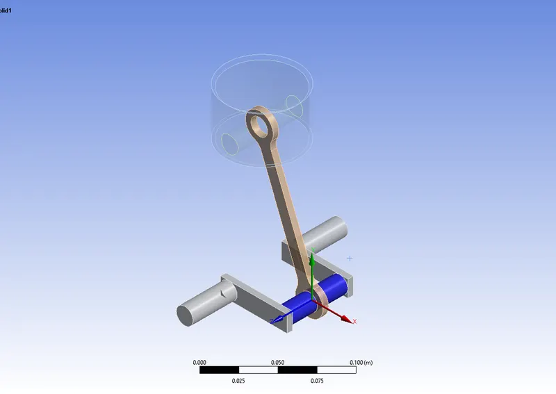
- Ground to Crankshaft Joint:
- Connection Type: Body-Ground
- Type: Revolute
- Reference: Ground
- Mobile: Crankshaft
- Degree of Freedom: RZ
- Other Settings: Default
- Image:
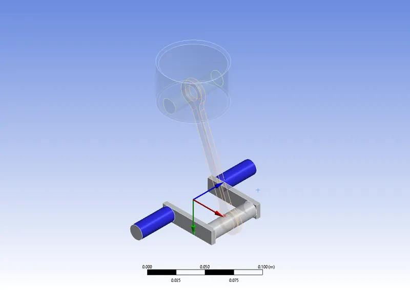
- Ground to Piston Joint:
- Meshing:
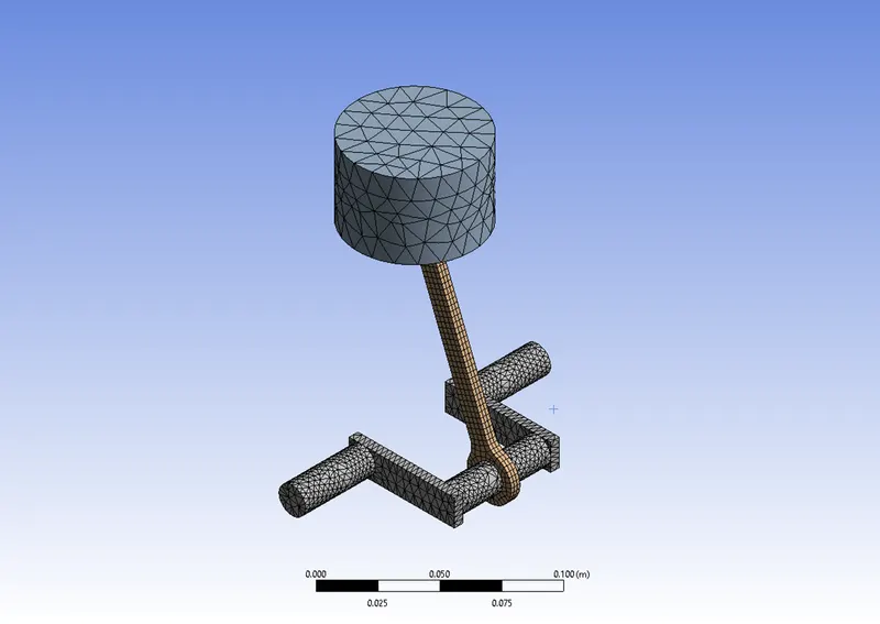
- Basic mesh size 2.5 mm
- Tetrahedral mesh for piston and crankshaft
- Hexahedral mesh for piston bar and rod
- Body sizing of 10 mm for piston
- Number of nodes 24105
- Number of elements 8702
- Results of mesh independent study presented later
- Image:
- Analysis Settings:
- The number of major time steps is set to 10.
- The duration of all the major time steps is 1 s.
- Auto time stepping is turned on and defined by time for all the major time steps.
- The initial time step is set to 0.1 s and all the latter time steps are bounded by 0.05 s and 1 s.
- Carry over time step is turned on for all the major time steps starting from the second step.
- Joint Load:
- Joint: Ground to Crankshaft
- Type: Rotational Velocity
- Magnitude: Tabular (Time) Data
- Plot:
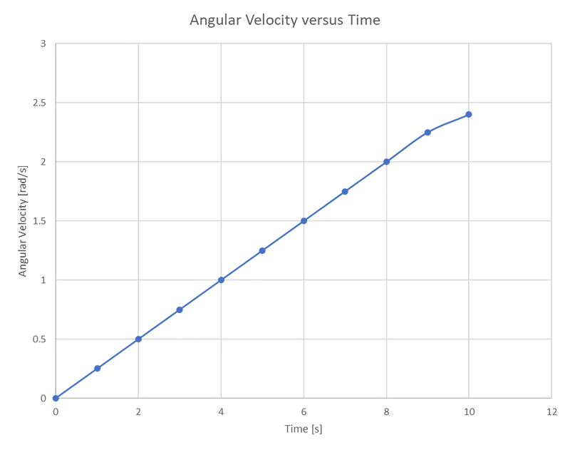
Results:
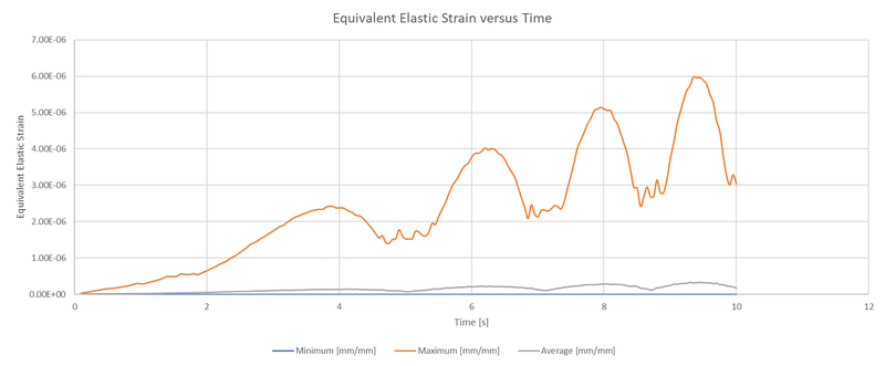
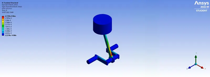
- Equivalent Elastic Strain:
- Plot:
- Contours:
- Plot:
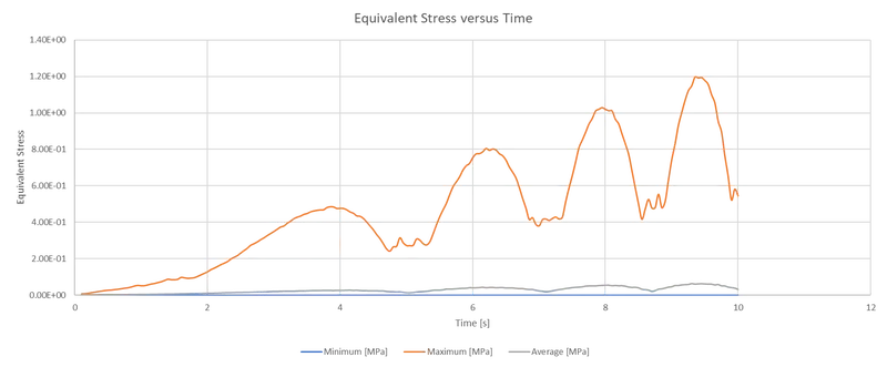
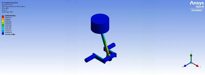
- Equivalent Stress:
- Plot:
- Contours:
- Plot:
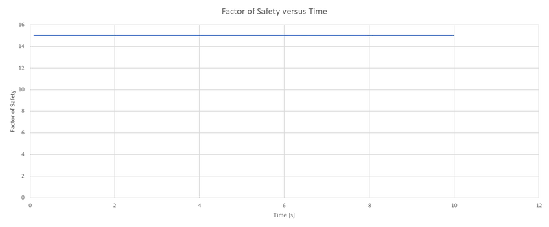
- Factor of Safety:
- Plot:
- Contours:
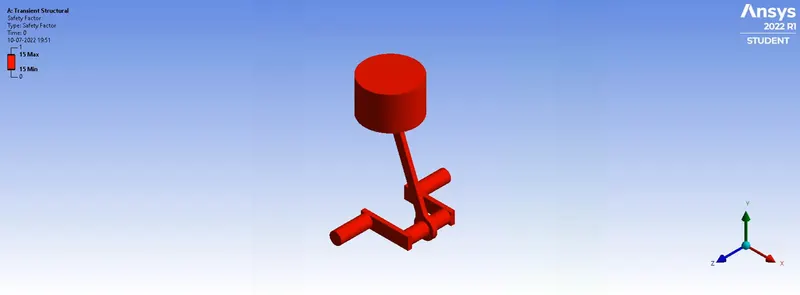
- Reason for this behavior of FoS has been provided in the conclusion.
- Plot:
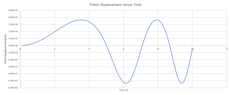
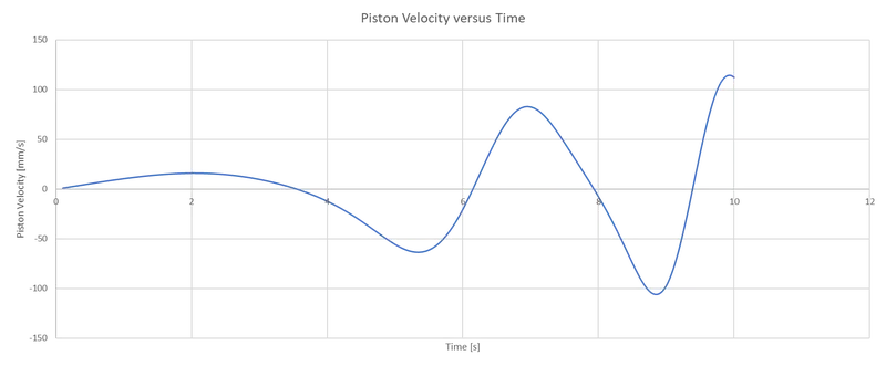
- Piston Kinematics:
- Displacement Plot:
- Velocity Plot:
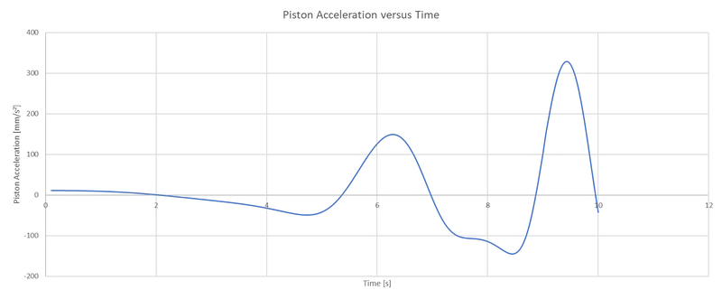
- Acceleration Plot:
- Displacement Plot:
Validation and Postprocessing:
- Calculations:
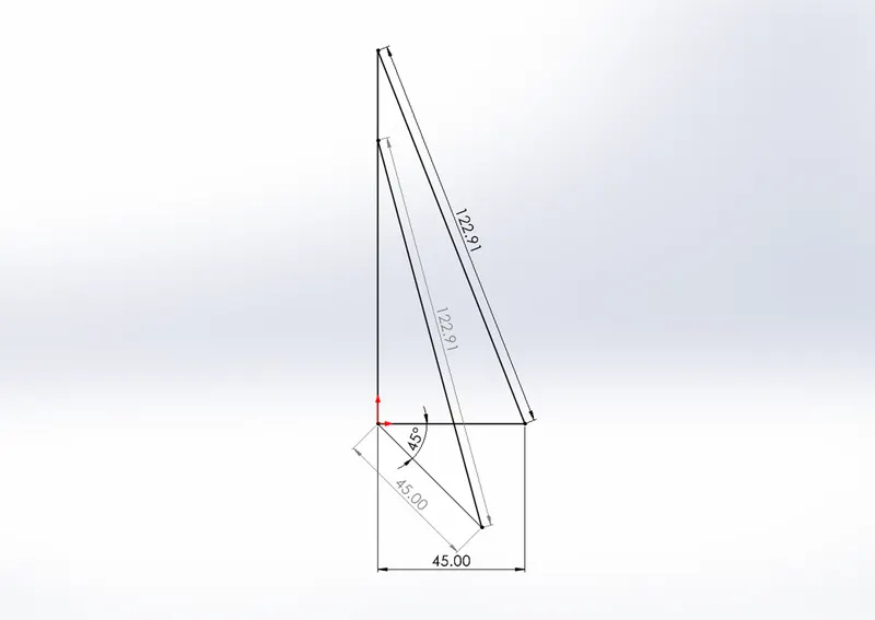
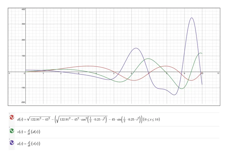
From measurements, `b=122.91` mm and `a=45` mm. Applying the Law of Cosines, the piston displacement comes out to be `∆y=√(b^2-a^2 )-(√(b^2-a^2 cos^2θ )-a sinθ )` for a general angular displacement `θ` of the crankshaft. In this case, `θ=1/2 αt^2` where `α=0.25` rad/s and `0≤t≤10` s. The geometry for `θ=45°` is shown.
- Plots:
- Grid Dependency Test Results (Results shown at `t=10` s i.e., at the end of the 10th step):
P1 - Mesh Element Size [mm]
P2 - Equivalent Elastic Strain Minimum [mm mm^-1]
P3 - Equivalent Elastic Strain Maximum [mm mm^-1]
P4 - Equivalent Elastic Strain Average [mm mm^-1]
P5 - Equivalent Stress Minimum [MPa]
P6 - Equivalent Stress Maximum [MPa]
P7 - Equivalent Stress Average [MPa]
2.5
3.31E-13
3.04E-06
1.65E-07
1.84E-08
0.546268824
0.030058728
4
3.66E-13
4.32E-06
3.21E-07
2.75E-08
0.860652721
0.057742123
5
1.02E-12
1.02E-05
1.02E-06
8.35E-08
2.021335067
0.187070472
7
3.47E-13
2.90E-05
3.08E-06
1.32E-08
5.785104066
0.49761785
Conclusion:
- The problem has been successfully simulated using the transient structural module of ANSYS for implicit non linear analysis.
- The factor of safety has reached the maximum limit imposed by ANSYS i.e., 15. That’s why it has been displayed as being constant throughout the model at all time steps.
- The actual piston kinematical plots and the calculated plots are in well agreement and differ only slightly. This is because the calculated plots considered just the rigid body motion and did not take into account the deformation of the individual components of the assembly.
Reference Paper:
- Finite Element Analysis of a Four-Cylinder Four Stroke Gasoline Engine Crankshaft (This paper however incorporates a Static Structural Analysis and the geometry used in the research paper is also vastly different from mine)