Independent Research Project
Project Topic:
- Flow visualization inside Tundish geometry using Tracer injection.
Obejective:
- To visualize the flow of tracer inside the domain and plot the Residence Time Distributon Curve (RTD) of tracer ath the outlet.
Significance:
- In many metellurgical industries, there is requirement of fine metal for better and high quality product.
- This is done with the help of TUNDISH.
- The Tundish allows a reservoir of metal to feed the casting machine while ladles are switched, thus acting as a buffer of hot metal, as well as smoothing out flow, regulating metal feed to the moulds and cleaning the metal.
==============================================================================
What is TUNDISH?
- The word Tundish originates from a shallow wooden dish with an outlet channel, fitting into the bungholeof a tun or cask and forming a kind of funnel for filling it. These were originally used in brewing.
- In general, any Tundish will accept flow and store a small amount of material, while dispensing material elsewhere, similar to a funnel.
- In contrast to a funnel, the purpose is generally to regulate flow, and achieve a more steady output with intermittent inputs, and the Tundish typically will take on a different shape.
- It is used to feed molten metal into an ingot mould to avoid splashing and give a smoother flow.
- The Tundish allows a reservoir of metal to feed the casting machine while ladles are switched, thus acting as a buffer of hot metal, as well as smoothing out flow, regulating metal feed to the moulds and cleaning the metal.
- Metallic remains left inside a Tundish are known as Tundish skulls and need to be removed, typically by mechanical means (scraping, cutting).
Flow Modifiers inside the TUNDISH.
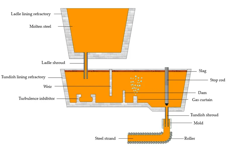
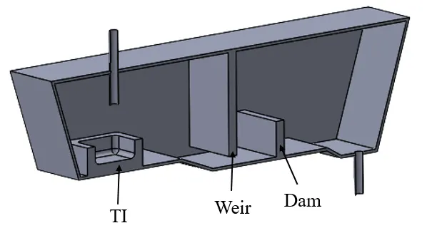
- Weir: It is mainly used to divide the inlet chamber and the outlet chamber. Controls the turbulence, enhances inclusion flotation and minimizes surface wave amplitude at the outlet.
- Dam: It orients the flow in the upward direction and dampens the short circuiting phenomena caused by weir.
- Turbulence Inhibitor: It is used to avoid the damage caused by the molten steel to the refractory lining. The high turbulence of the incoming stream can spread throughout the Tundish if the flow is not properly controlled. It may cause the disturbance of the steel/slag interface and thereby promote slag entrainment
- Ladle Shroud: Inlet of Tundish.
- Tundish Shroud: Outlet of Tundish.
- Stop Rod: Gives flexibility of controlling fluid flow rate.
Why Simulation?
- The simulation is carried out using “Water model” approach.
- It is difficult to manufacture different configuration of Tundish and pour the liquid molten metal for the sake of data collection and efficiency of the system.
- The alternate way of carrying out such task is to simulate the same phenomena using a computer.
- This approach is very budget friendly and can be validated experimentally by water model.
- Water model is a substitute of molten liquid.
- A CFD engineer tries to visualize the flow pattern taking place inside the Tundish geometry via injecting a tracer into the system for few seconds.
What to simulate?
- Discrete Phase Model (DPM) – This is to consider the inclusions or non-metallic particles in the model.
- Perform steady-state analysis until the flow field becomes steady.
- Create report of mass flow rate at the outlet to make sure when the flow stabilizes.
- Then, perform a transient state for DPM to plot Residence Time Distribution (RTD) curve.
- Drawback of this procedure is the boundary condition and number of particles injected into the domain.
- For DPM, a User Defined Function has to be written for the particles fate after hitting the top surface.
- This will give a better justification for the seperation efficiency.
- Next is to include the slag layer, bubble formation etc. This is done using Multiphase simulation.
- Other way is to perform Species Transport to calculate RTD curve. This approach is the most economical approach.
==============================================================================
Current Study:
- The current study specifically concentrates on how the flow is behaving inside the Tundish.
- Two cases were considered,
1) Bare Tundish.
2) Tundish with turbulence inhibitor, weir and dam.
- For both the cases graph of Residence Time Distribution was plotted.
- It is expected that the tracer reaches the outlet faster in the case of bare Tundish and opposite for the other case.
Procedure:
- Few assumptions are made:
1) 3D Navier-Stokes equations are solved.
2) Iso-thermal condition is considered and energy equation is turned off.
3) For turbulence, k-epsilon realizable model is solved.
4) Heat loss from the surface is neglected.
5) Top surface is considered free surface and is flat at fixed level.
6) Slag layer and gas injection is not considered.
- For first 2 seconds the tracer is injected into the domain and for the rest of the simulation the tracer is not injected. It is convected by the water.
Transport Equations:
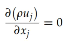
- Continuity:
- Momentum Equation:

- Energy Equation: (not considered)

- ρ is the density.
- Cp is the heat capacity.
- µt is the turbulent viscosity.
- Prt is the turbulent Prandtl number.
- ST represents the source term of energy equation.
Turbulence Equation:
- K-epsilon realizable model:

- k is the turbulent kinetic energy.
- ε is the turbulent energy dissipation rate.
- µ is the molecular viscosity.
- µt is the turbulent viscosity.
- Gk represents the generation of turbulent kinetic energy due to the mean velocity.
- YM symbolizes the contribution of the fluctuating dilatation in compressible turbulence to the overall dissipation rate.
- υ is the kinematic viscosity.
- σk and σε are the turbulent Prandtl numbers for k and ε, respectively.
Tracer Equation:
- Passive Scalar equations are solved which includes instantaneous addition of the tracer and is generally known as E-Curve.
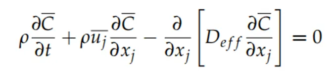
- Deff is the effective diffusivity.
==============================================================================
Geometry:
- Case 1:
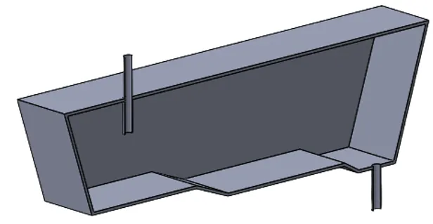
- Case 2:
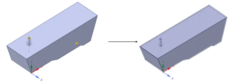
- Select volume extract tool.
- Select the inner edges of the inlet and outlet.
- Generate the volume.
Meshing:
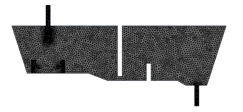
- One half of the domain is considered due symmetrical nature of the geometry.
- The minimum and maximum element size is 40 mm.
- Further refinement can be done by adding inflation layers near the wall.
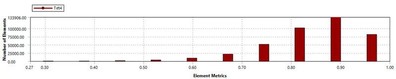
- Desired mesh element metrics should be greater than 0.05.
Named Selection:
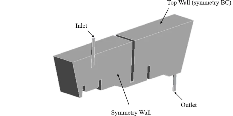
- Select desired face or edge and give name to the boundary.
- This helps in assigning the correct boundary condition.
Setting up Physics:
>> General:
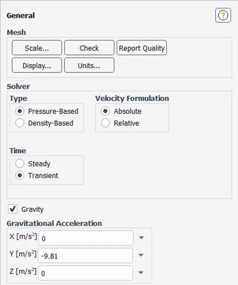
- Transient simulation
- Gravity = -9.81 in y-direction.
- Pressure-Based solver is chosen because of low mach number. (M<0.3).
>> Turbulence Model:
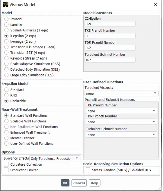
- Select realizable k-epsilon model.
- Better wall treatment compared to standard model.

- The selection of the turbulence model is entirely based on the kind of physics being solved.
- If the presence of adverse pressure gradient is know, then k-epsilon model is not appropriate for simulation.
- One must choose k-omega model, as it does not have damping function to resolve the viscous-sub layer.
- The drawback of k-omega model is, that it sensitive to initial condition.
- To avoid such phenomena other model ie. k-omega SST model is used.
- In k-omega SST model, near the wall k-omega model is used and far away from the wall k-epsilon model is used.
- This is achieved by introducing 'blending function' 'f' into the equation.
- f varies from 1 to 0.
- f=1 indicates we are solving k-epsilon model and we are away from the wall.
- Conversely, if f=0 then we are solving k-omega model and we are near the wall.
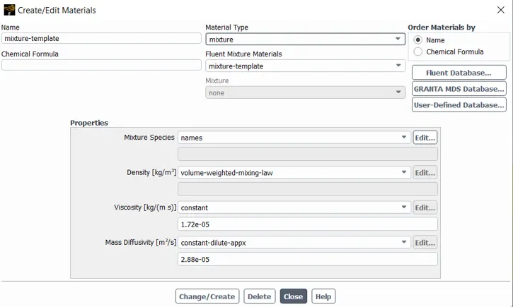
>> Material Create/Edit:
- Copy water from the fluent database.
- Again copy water from the fluent database and name it tracer.
>> Species Transport Equation:
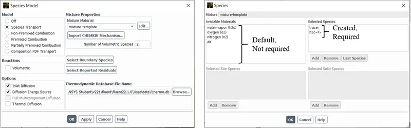
- Enable Species transport.
- It contains default species in the mixture-templet.
- Default species are not required as water and tracer are the species of interest.
- Inorder to remove the default species, navigate to the 'Create/Edit Material', make sure mixture is selected inder 'Material Type' drop down.
- Select required species and remove the ones which are not required.
- Add tracer and then add water.
- Select volume-weighted average for density formulation.
- This is used for non-ideal fluids and gives a flexibility to deselect energy equations.
>> Boundary Condition:
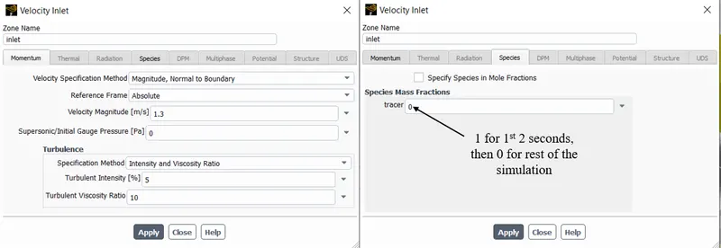
- Inlet – Velocity inlet – 1.3m/s; mass fraction of tracer as 1 for 1st 2 seconds of the simulation.
- Top_wall – Symmetry.
- Symmetry – Symmetry.
- All the walls as wall (side, bottom etc.).
- The mass fraction of tracer is 1 for 1st 2 seconds and for the rest of the time period the mass fraction of tracer is 0.
>> Solver Method:
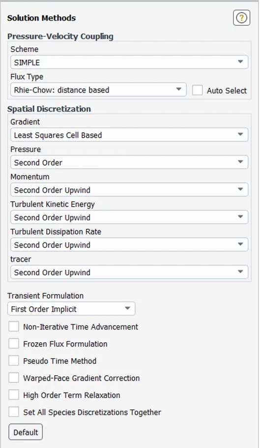
- SIMPLE algorithm is chosen. It is recommended by Ansys for Transient simulation.
- Second Order Upwind for other parameters for better accuracy.
- 10 iterations per time step.
- Create Vertex Average and Mass Weighted Average report at outlet.
- Time step size is 1 and number of time steps is 1000.
- Computational time was around 7 to 8 hours.
==============================================================================
Results and Discussion:
Case 1:
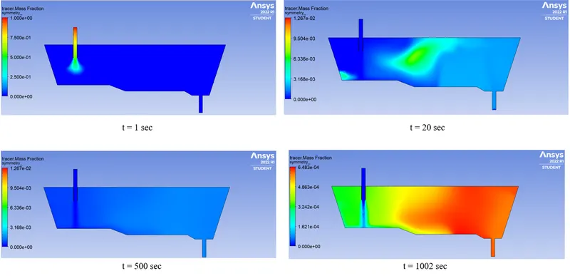
- Contour Plots of Tracer Mass Fraction at different seconds:
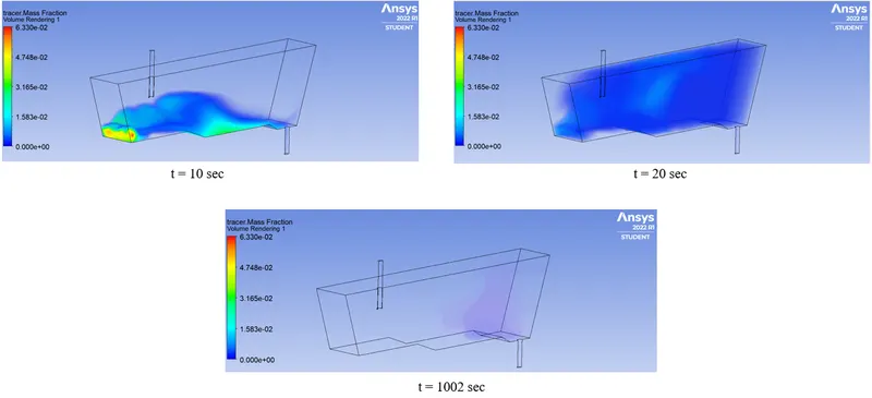
- Volume Rendering of Tracer Mass Fraction at different seconds:
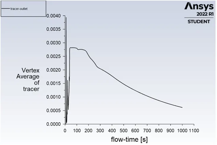
- Residence Time Distribution Curve:
Case 2:
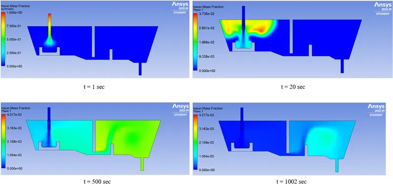
- Contour Plots of Tracer Mass Fraction at different seconds:
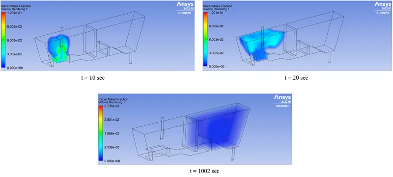
- Volume Rendering of Tracer Mass Fraction at different seconds:
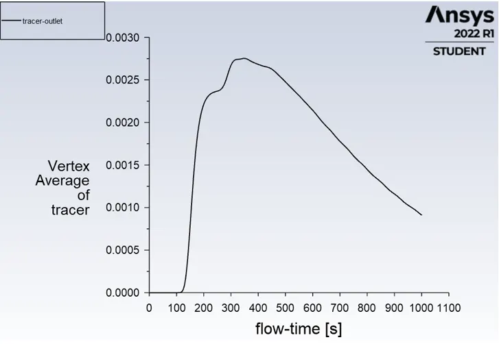
- Residence Time Distribution Curve (RTD):
Conclusion:
- From contour plots, it is quite evident that the flow is well regulated in case 2.
- The flow modifiers try to delay the tracer exit very well.
- Comparing the RTD curve, mass fraction of tracers is seen at a very short span in case 1 and for case 2, the mass fraction for tracer is seen after 100 to 130 seconds of delay.
- This concludes that the Tundish configuration with flow modifiers are better suited for flow uniformity, steady flow at output and better seperation of non-metallic particles due to delay in tracer mass fraction at the outlet.
Future Work:
- Include particles to replicate non metallic inclusions.
- Consider slag layer on the top surface.
- Inject gas for small particle entrapment.
- Include the effect of inlet velocity on flow field.
- Variation in design and placement of flow modifiers.