Independent Research Project

The Fatal crash of Air India Boeing 737-800 last month due to its overrun at Kozhikode airport once again brings forth the ‘dangers on the runway’.
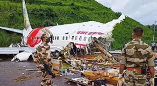
It gives jitters when a pilot makes an approach to land, especially, in the rainy season. Just like any other surface condition, runways also get slippery when it is wet, making take-off and landing of aircrafts difficult and at time.
During take-offs and landings on wet runways, water penetrates between tyres and runway surface resulting in the formation of water pressure that weakens the grip of the tyre on the surface. This pressure increases the speed of the aircraft and it is called hydroplaning.
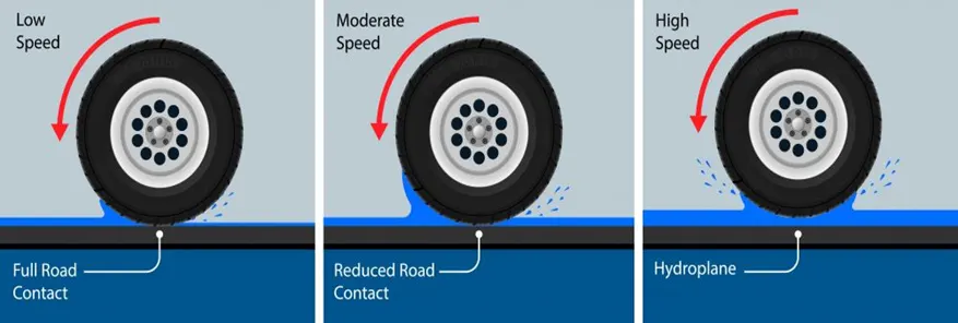
Directorate General of Civil Aviation. (DGCA) has norms for water on a runway.
2.9.5 Whenever water is present on a runway, a description of the runway surface conditions shall be made available using the following terms:
- DAMP — the surface shows a change of colour due to moisture.
- WET — the surface is soaked but there is no standing water.
- STANDING WATER — for aeroplane performance purposes, a runway where more than 25 per cent of the runway surface area (whether in isolated areas or not) within the required length and width being used is covered by water more than 3 mm deep
Objective -
- To create a system which will remove water temporarily from the runway so that aeroplane wheels can come in direct contact with the runway to avoid hydroplaning.
- In which Aircraft will use its own bleed air to remove the water near tires.
- Boeing 737 tyre and bleed air configuration are taken as the reference value.
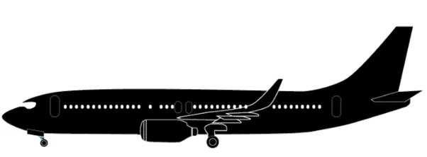
Boeing 737-800
- Tyre Dimension-
Size of the nose tyre of the 737 NG 27x7.75-15 (27-inch diameter, 7.75-inch width and 15inch width size).
Size of the main gear tyre is H44x16.5-21 (44-inch diameter, 16-inch width and 21inch width size).
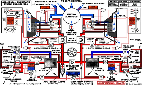
Bleed Air - Compressed air is taken from the compressor stage of a gas turbine upstream of its fuel-burning sections.
- The minimum pneumatic duct pressure (with anti-ice off) for normal operation is 18psi.
- Maximum Pressure is 60 psi.
While landing less power is required from the engine and during landing, no pressurised water is required in the lavatory.
Geometry -
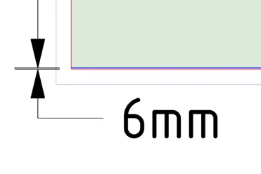
Created the 2D representation of a portion of the runway having 6mm deep waterlogging. The nozzle of 50mm diameter is placed at a height of 558.8 mm which is the centre point of the aircraft wheel (Diameter-44 inch = 1117mm) which means nozzle is approximately at wheel axle.
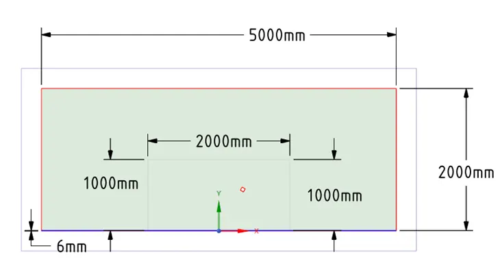
Case .1 - Changing the speed of air with a constant nozzle angle at 60°
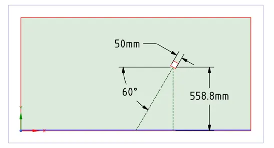
Case .2 – Changing the angle of impact of the nozzle
2.A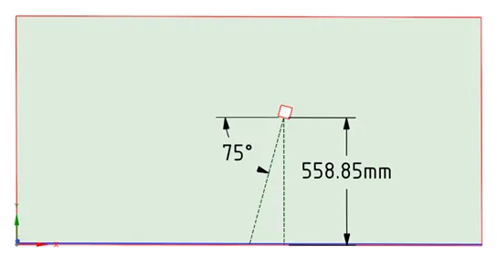
2.B 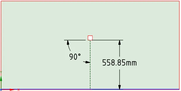
Meshing & Name Selection -
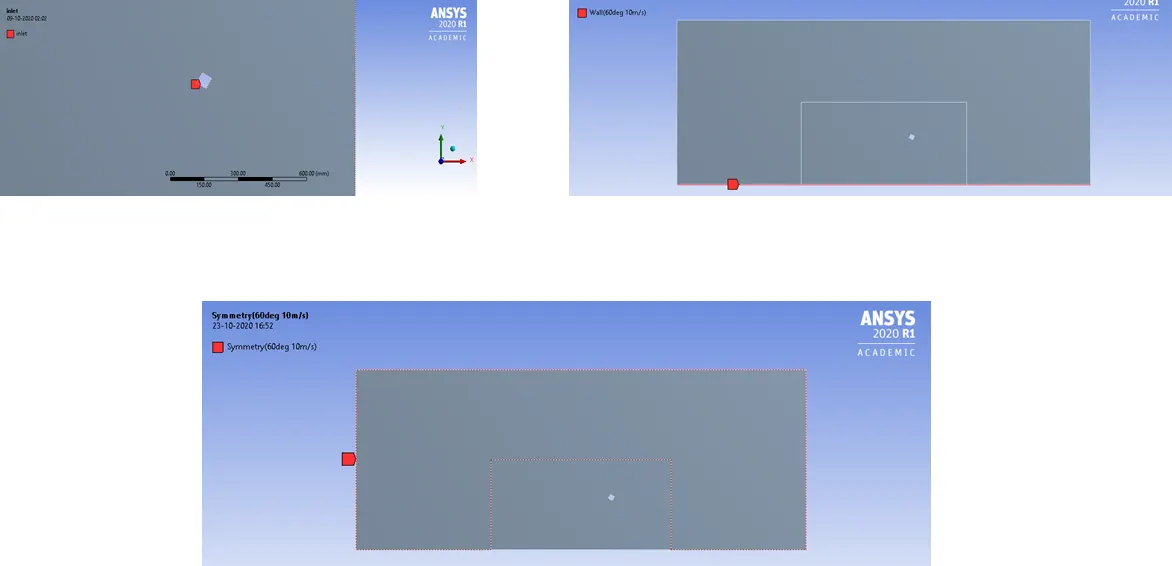
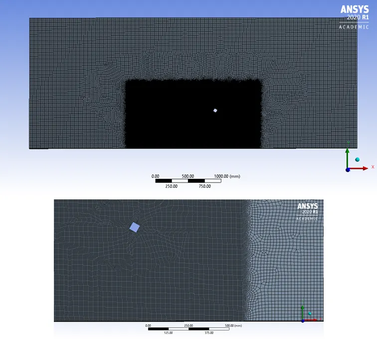
Meshing
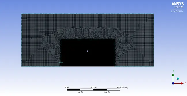
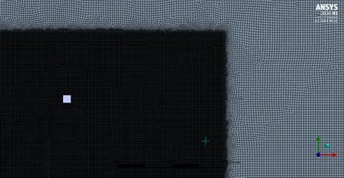
- Element Size – 20mm
- Face sizing – 5mm
Sizing Method is used to fine the mesh near the nozzle
Capture Proximity – Yes
Setup
- Solver Type: Pressure base, Transient Velocity with the K-epsilon Viscous Model
- Absolute Gravity:-9.81m/s along with y-direction
- The multiphase model with the implicit formulation is used.
- Material Primary Phase -air and Secondary Phase-water
Boundary conditions:
Case-1.A Jet Angle 60°, Inlet velocity-10m/s
Case-1.B Jet Angle 60°, Inlet velocity-20m/s
Case-1.C Jet Angle 60°, Inlet velocity-30m/s
Case-2 Jet Angle 75°and 90°, Inlet velocity-30m/s
- The solution runs for 500-time step with time step size 0.005s. If required increased time step for some cases.
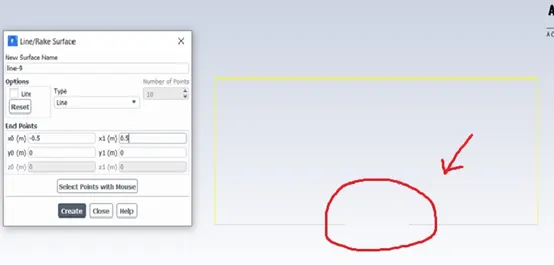
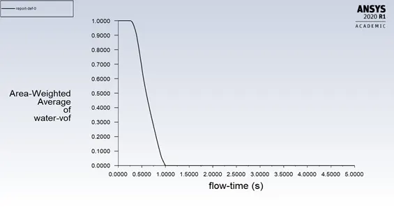
A line is created to capture the amount the water displaced from the jet. Line's centre lies at the point which projected from the centre of the nozzle towards the ground. Report definition for PHASE (Water) is assigned to that line.
Results and Discussion
Case 1.A
Jet Angle 60°, Inlet velocity-10m/s
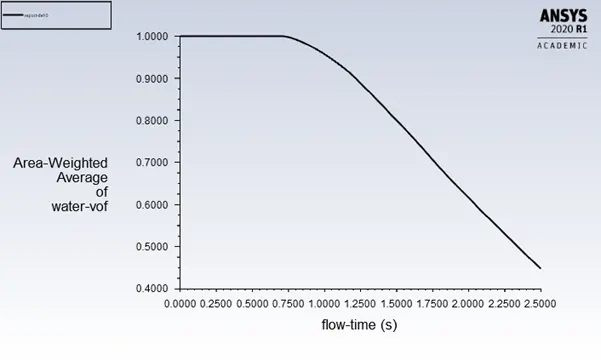
Air jet which is at 60° from the horizontal and at the velocity of 10m/s is unable to remove water completely. Only 58% is removed
Case 1.B
Jet Angle 60°, Inlet velocity-20m/s
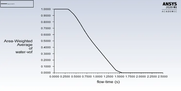
It took 1.5s to remove the water after some time the jet got deflected and curved in. Jet's impact position changed which can lead to retaining water near the wheel.
Case 1.C
Jet Angle 60°, Inlet velocity-30m/s
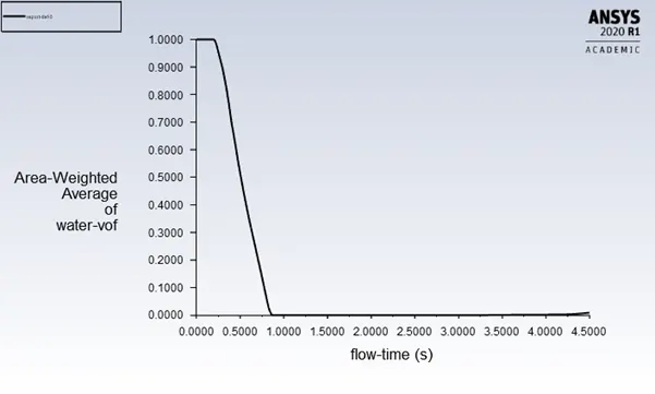
In this case, water removed very swiftly but jet deflected. At 4.5-sec water begin to come back in the earlier position.
Case 2.A
Jet Angle 75°, Inlet velocity-30m/s
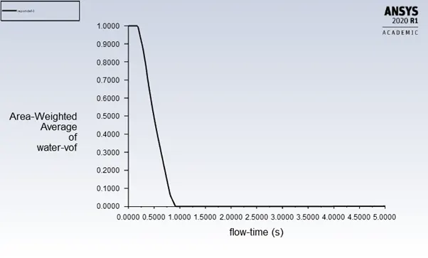
After changing the angle by 15° still jet deflected.
Case 2.B
Jet Angle 90°, Inlet velocity-30m/s
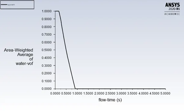
In this case, jet didn't deflect and water removed within 1 sec and jet shape is also maintained.
|
Case |
Angle |
Velocity |
Water Content removed |
Time |
|
Case 1.A |
60° |
10 |
58 % |
2.5s |
|
Case 1.B |
60° |
20 |
*100% |
1.55s |
|
Case 1.C |
60° |
30 |
*100% |
0.8s |
|
Case 2.A |
75° |
30 |
*100% |
0.8s |
|
Case 2.B |
90° |
30 |
100% |
0.8s |
*unable to predict the constant water content, jet's impact position changed.
From the above table, it's clear that verticle jet position with high air velocity performed very well and fulfilled the requirement.
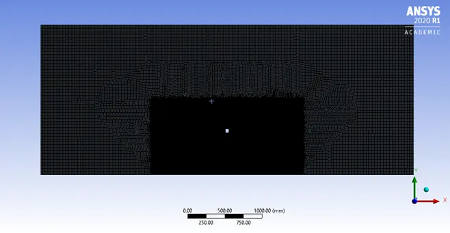
So we proceeded for mesh independency test for CASE 2.B.
Mesh Independency Test
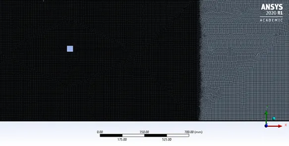
1.
- Element Size – 15mm
- Face sizing – 3mm (to fine the mesh near the nozzle)
Capture Proximity – Yes
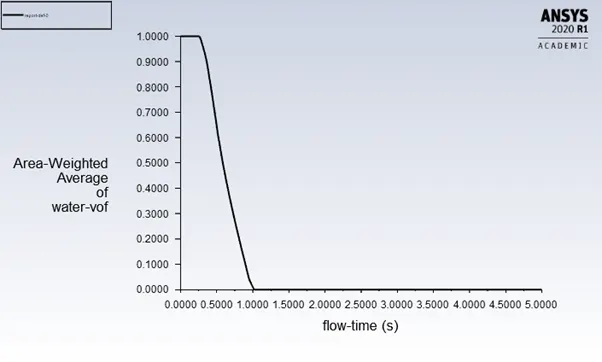
2.
- Element Size – 15mm
- Face sizing – 1.5mm (to fine the mesh near the nozzle)
- Capture Proximity – Yes

- Dewatering of runway is more with higher velocity
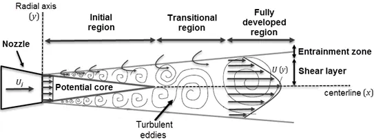
- Nozzle inclined at 60° and 75°angle are clearing water from the front part of the tyre but free jet stream gets deflected because the high-speed jet entrains its ambient fluid, leading to the fluid velocity difference between the near and far away jet boundary regions, due to the viscous interaction between the jet and the surrounding medium. With the continuous energy exchange and turbulent diffusion between the jet and surrounding medium, a series of vortices will be generated on both sides of the jet which let to the deflection of the jet.
- For inclined jet, the distance to reach the ground is more as compared to the vertical jet, which means vertical jet has less diffusion between the jet and surrounding which results in the steady jet.
Future Scope
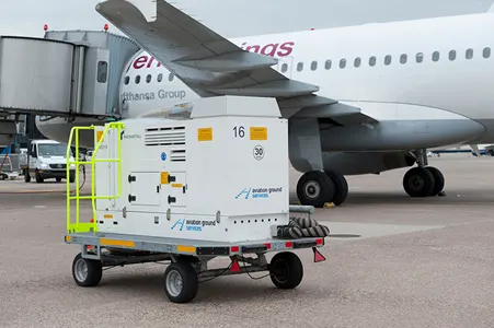
- Use of Air Starter Unit
Air start unit is used for starting aircraft engines equipped with air starter. These units already present over at airport can be utilized for such purpose.
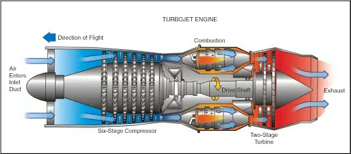
- Using exhaust air
Creating a jet stream from Aircraft exhaust which is high in temperature, can also be helpful to evaporate the water.
Reference
- Songqiang Xiao, Zhaolong Ge, Qingyang Ren, Jialiang Liu & Haiyang Wang (2020) Numerical analysis on the flow field structure and deflection characteristics of water jets under nozzle moving conditions, Engineering Applications of Computational Fluid Mechanics, 14:1, 1279-1301, DOI: 10.1080/19942060.2020.1822210
- K.M.Pandey and Virendra Kumar CFD Analysis of Twin Jet Flow At Mach 1.74with Fluent Software January 2011 International Journal of Environmental Science and Development 1:423-428 DOI: 10.7763/IJESD.2010.V1.81
- Tyre Specification – Dunlop Aircraft Tyres.
- www.dunlopaircrafttyres.co.uk/aircraft/boeing-737-next-generation-tires
- Boeing Bleed Specification - www.b737.org.uk/pneumatics.