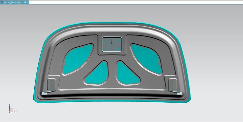
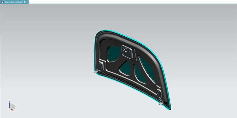
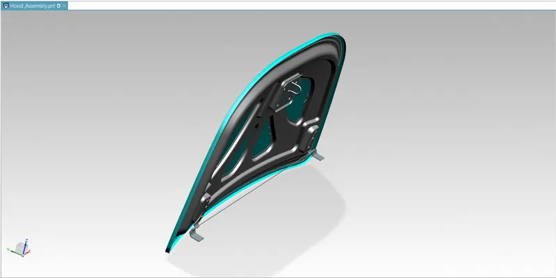
Hood design-Week 2
Aim - Design a Automotive hood using master section in NX-Cad.
Objective -
- Design Automotive hood
- Create a assembly of hood including hood Inner pannel, Outer panel, Hinge assembly, Striker etc.
Master section-
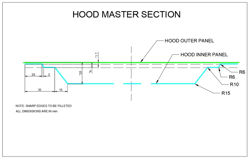
From master section we can see that we have to create 3 flanges and assembly is symmetric so its easy to work on half portion and mirror it to the axis.
Criteria -
- Outer Panel Thickness = 0.75mm
- Inner Panel Thickness = 0.75mm
- Reinforcement Thickness = 1.5mm
Hemming data -
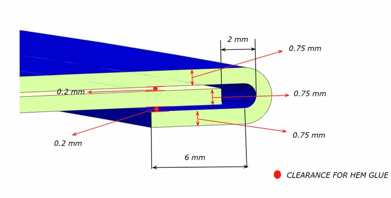
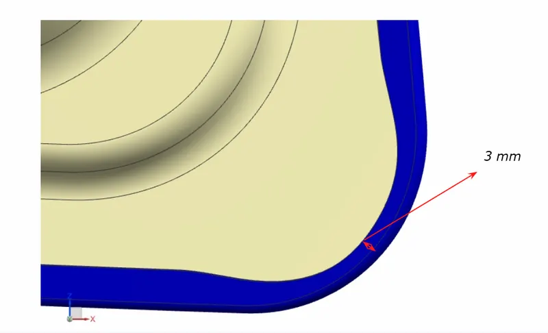
Corner relief -
What is hood?
A car Hood also referred to as bonet in some countries is the hinged cover that rests over the engine of a front-engine vehicle. Its purpose is to provide access to the engine for repair and maintenance. Car hoods are typically constructed from steel and sometimes from aluminum.
- On front-engined cars, the hood may be hinged at either the front or the rear edge, or in earlier models (e.g. the Ford Model T) it may be split into two sections, one on each side, each hinged along the centerline.
- A further variant combines the bonnet and wheel arches into one section and allows the entire front bodywork to tilt forwards around a pivot near the front of the vehicle.
- Hoods are usually made from the same material as the rest of the body. This can be steel, aluminum, fiberglass, or carbon fiber. However, some aftermarket companies produce fiberglass or carbon fiber steel hood replacements to make the vehicle lighter.
- The hood release system is common on most vehicles and typically consists of an inner hood latch/lock handle, a hood release cable, and a hood lock assembly. The hood lock handle is usually located under the steering wheel, next to the driver’s seat, or in the door frame
- For racing cars or vehicles with aftermarket hoods (that do not use the factory latch system) the hood can be held down by hood pins. Some aftermarket hoods that have a latch system still have hood pins to keep the hood buttoned down if the latch fails.
Deep Drawing -
Deep drawing is a sheet metal forming process in which a sheet metal blank is radially drawn into a forming die by the mechanical action of a punch. It is thus a shape transformation process with material retention. The process is considered "deep" drawing when the depth of the drawn part exceeds its diameter.
Defination -
The deep drawing process is a forming process which occurs under a combination of tensile and compressive conditions. A flat sheet metal blank is formed into a hollow body open on one side or a hollow body is formed into a hollow body with a smaller cross-section
Types -
- Deep drawing with tools
- Deep draing with active means
- Deep drawing with active energy
In the automotive industry, deep drawing is usually carried out using rigid tools.
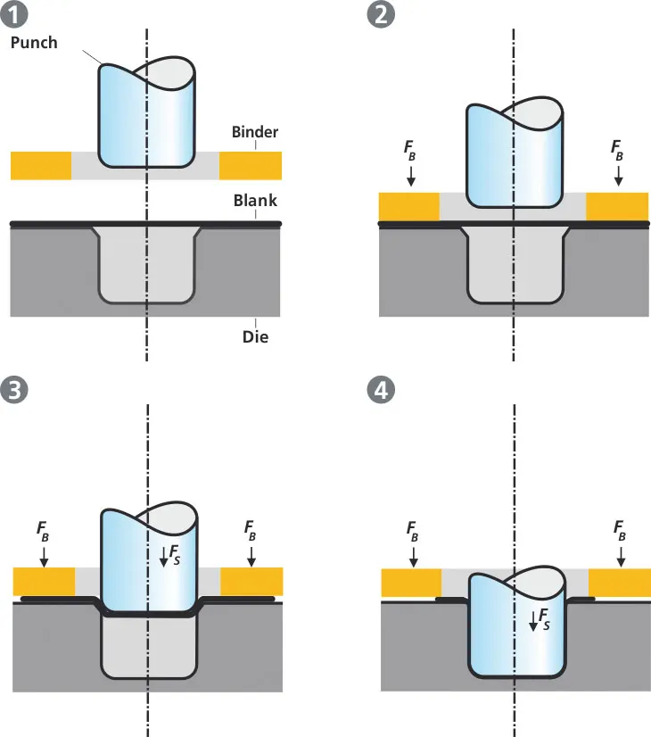
- The figure illustrates the deep drawing process. The rigid tools consist of a punch, die and binder. In deep drawing, the plate holder closes after the metal sheet blank has been inserted.
- Next the sheet is clamped between the die and the binder. This process slows down the flow of the sheet while it is being drawn and thereby prevents wrinkles from forming under the binder. The punch stretches the sheet over the die radius and forms it in the die. The amount of punch force necessary for forming is thereby continually increased up to the lower dead center of the punch.
- Whereas in pure deep drawing there is no reduction of sheet metal thickness, forming is achieved in stretch forming purely as a result of a decrease in sheet metal thickness. Stretch forming is extensively used for the forming of only slightly curved parts with low depth of draw (e.g. roofs, doors).
- When drawing complex car body parts in practice, there is usually a combination of stretch and deep drawing involved. It is necessary that the sheet metal is stretched as well as possible without reaching the material’s limits (e.g. splits, wrinkles).
Hemming Operation
- Hemming is a forming operation in which the edges of the sheet are folded or folded over another part in order to achieve a tight fit. Normally hemming operations are used to connect parts together, to improve the appearance of a part and to reinforce part edges.
- In car part production, hemming is used in assembly as a secondary operation after deep drawing, trimming and flanging operations to join two sheet metal parts (outer and inner) together. Typical parts for this type of assembly are hoods, doors, trunk lids and fenders.
- The accuracy of the hemming operation is very important since it affects the appearance of the surface and surface quality. Material deformations, which occur during the hemming process, can lead to dimensional variations and other defects in parts. Typical hemming defects are splits or wrinkles in the flange, material overlaps in the corner areas or material roll-in. This is why it is important to use simulation tools in order to, on the one hand, better understand the hemming process and, on the other hand, significantly reduce the number of “trial and error” loops during tryout und production.
Types -
1) Conventional Die hemming
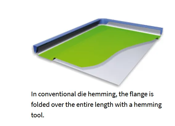
- Conventional die hemming is suitable for mass production. In die hemming, the flange is folded over the entire length with a hemming tool. Normally the actual hemming is a result of a forming operation in which the flange is formed with a hemming tool after the drawing and trimming operations have been completed.
- The formed flange is then hemmed in several process steps. These steps include, for example, the pre-hemming and final hemming depending on the respective opening angle of the flange. Production plants for conventional die hemming are very expensive, but the cycle times are very low.
2) Roll Hemming
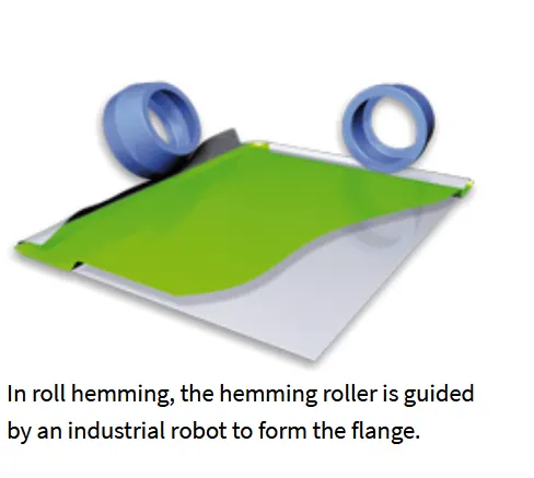
- Roll hemming is carried out incrementally with a hemming roller. An industrial robot guides the hemming roller and forms the flange. Roll hemming operation can also be divided into several pre-hemming and final hemming process steps.
- Roll hemming is very flexible to use and tool costs are significantly lower as compared to those of conventional die hemming. However, the cycle times are much higher since the hemming is realized using a hemming roller which follows a defined path.
Procedure
lets jump into NX-Cad and lets see the procedure.
Open NX-Cad
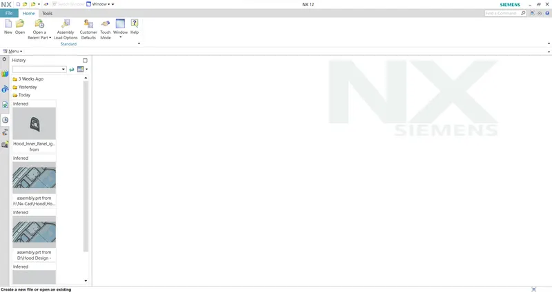
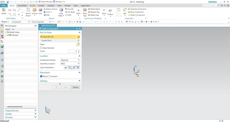
Create new assembly file ( We have to create inner panel from outer panel skin data)
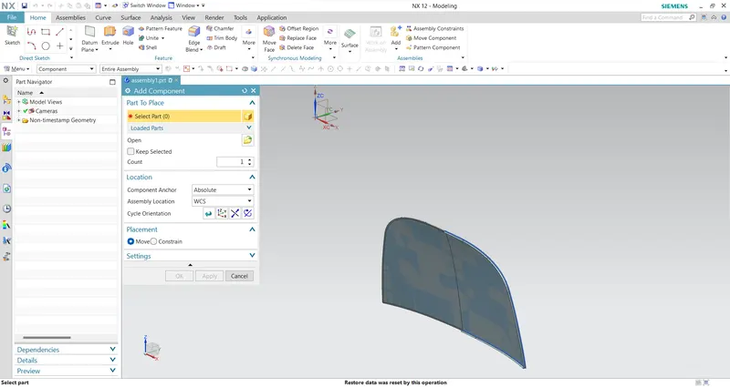
Load the outer panel of hood
Similarly load remaining parts (Hinge assembly, Striker)
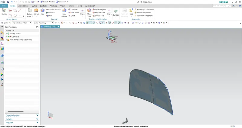
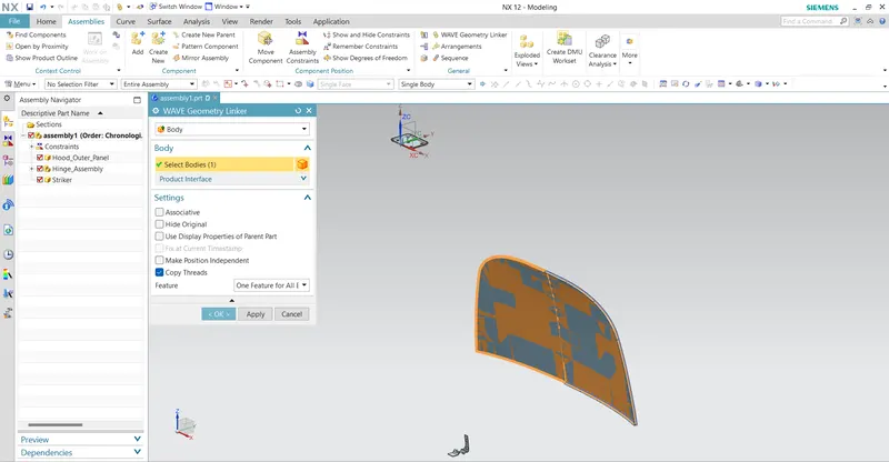
Using wave geometry linkup Create a inner panel from outer panel skin data
Now trim the sheet in two part so we can work on one part and mirror everything
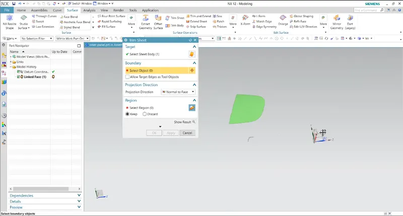
Rename trimmed surface and offset the surface by 20mm
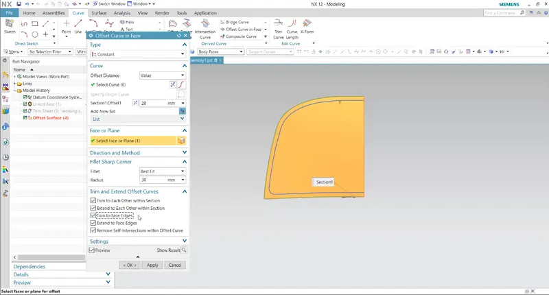
Boundry is created
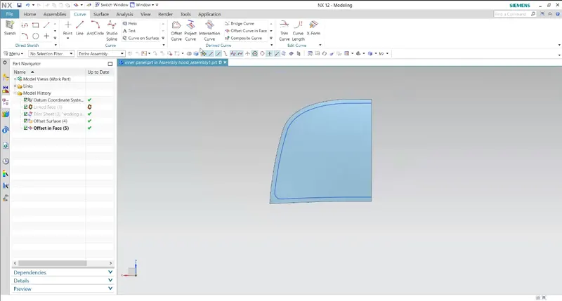
Now trim the sheet with created boundry
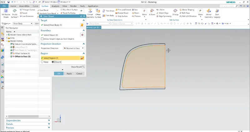
We have trimmed sheet
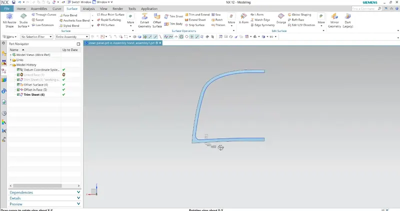
Hide the trim sheet and make working surface visible
Noe offset the surface from working surface by 4mm
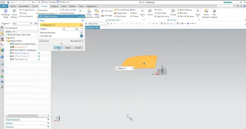
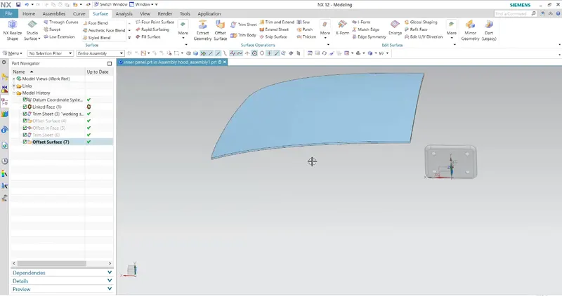
Now hide the offset surface and make working surface visible
First flange is created now second flange have to created
Now offset the curve in face (22 mm) and avoid sharp corner by selecting best fit (marked area)
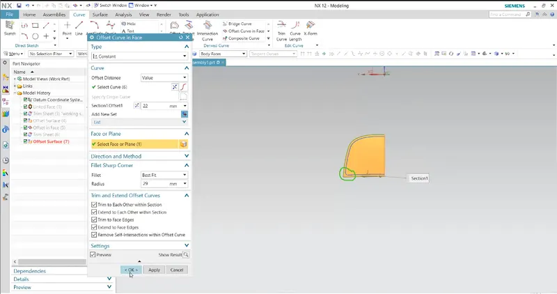
similarly create second boundry at 35 mm offset and trim the sheetwe will get our second flange
Now for third flange offset the surface by 25mm
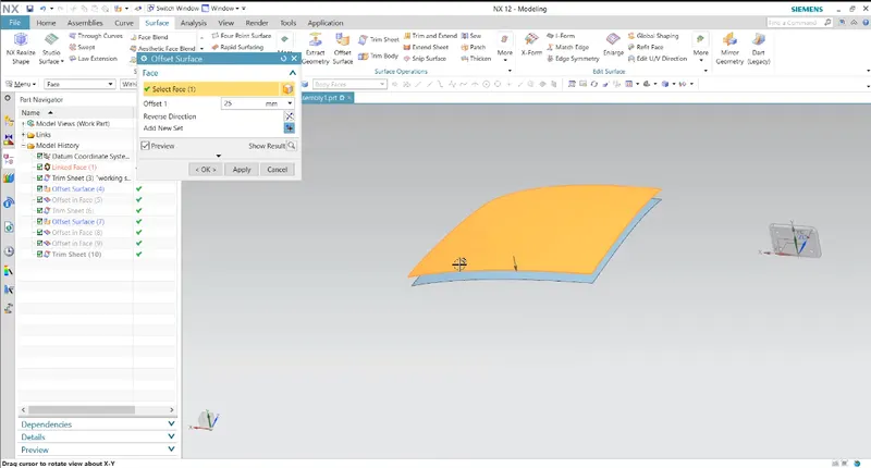
Hide working surface and we have our offset surface
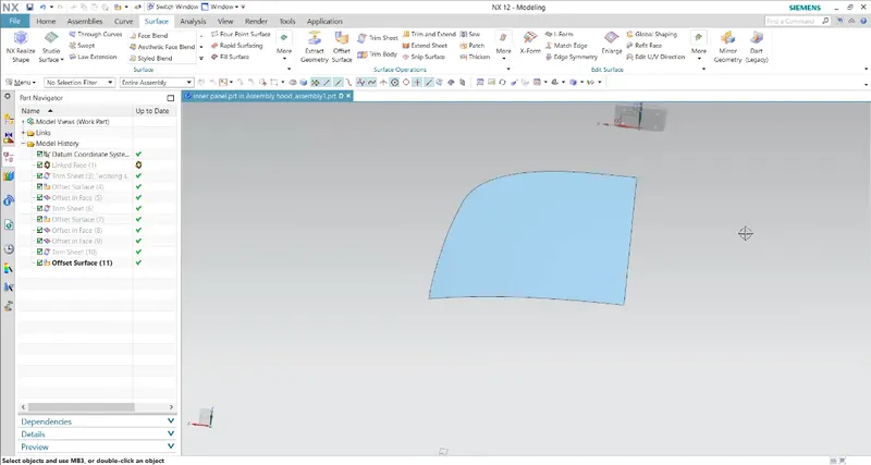
offset the surface by 50mm for last flange
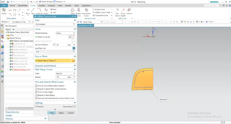
Boundry is created now trim the sheet
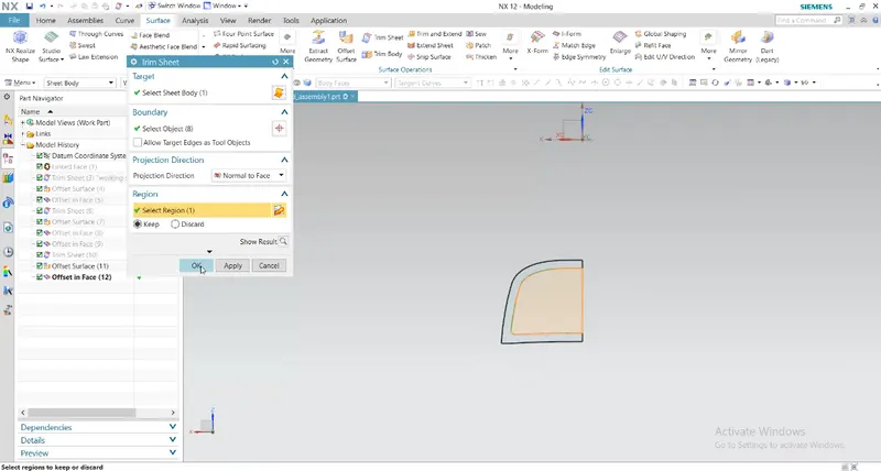
We have all three flanges here
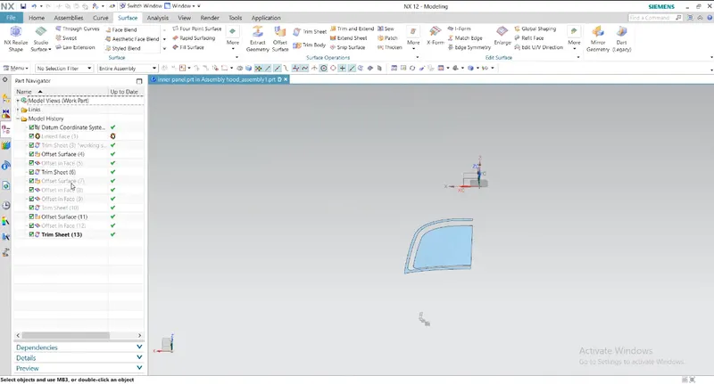
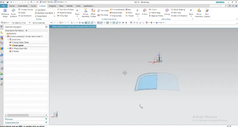
All offset are from working surface
Now we have all flanges we have to joint these together for this we have option called through curve b seleting these option we have to select curve for another curves select the add set and select another curve and apply a joint operation
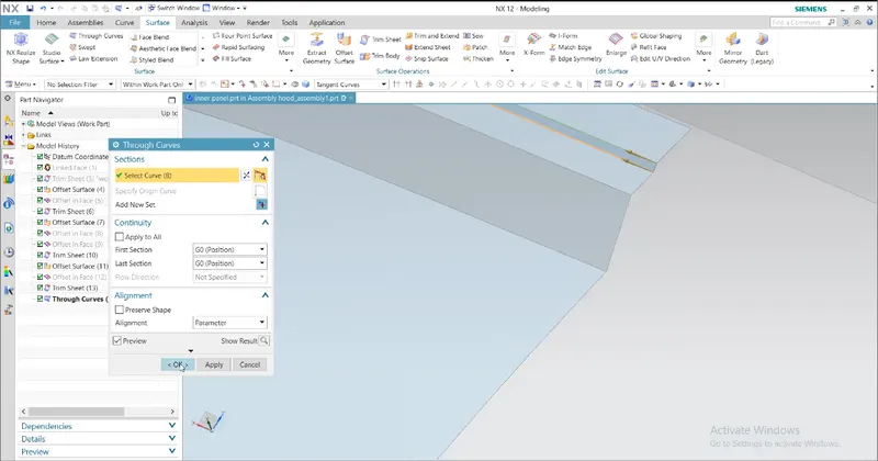
We have our joined surfaces
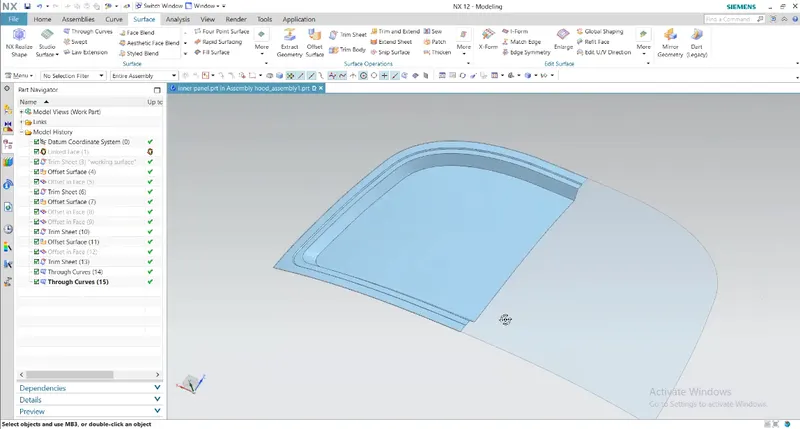
Now we need to apply blend feature we have face blend and edge blend before these use sew operation and sew the all surfaces together so we can use edge blend
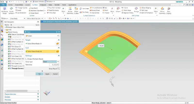
Now we have one complete body
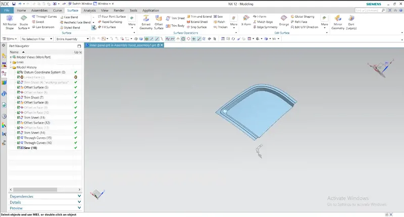
Now we can use edge blend by given radius. if radius not given we can taken it 3 times the thickness of sheet. In our case blend radius is given as 6,10 and 15mm so apply it.
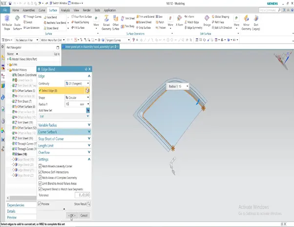
We have our complete edge blend
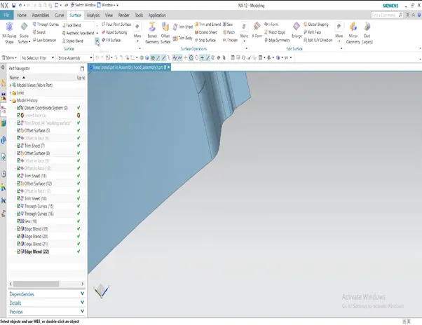
Now we have to create a emboss to remove heat from engine compartment
We need to create a datum plane and sketch on it and then project sketch on surface on create a emboss over there
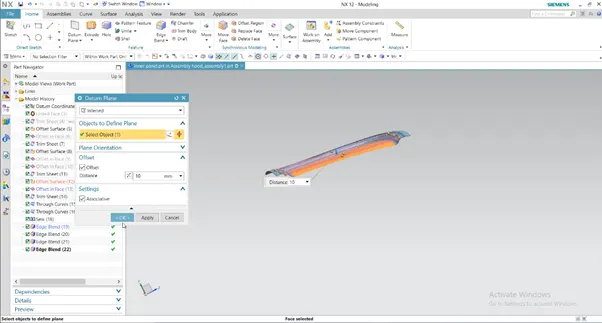
We have new datum plane lets sketch on it
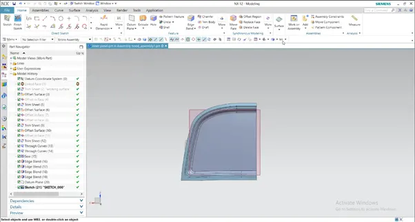
Make some offset
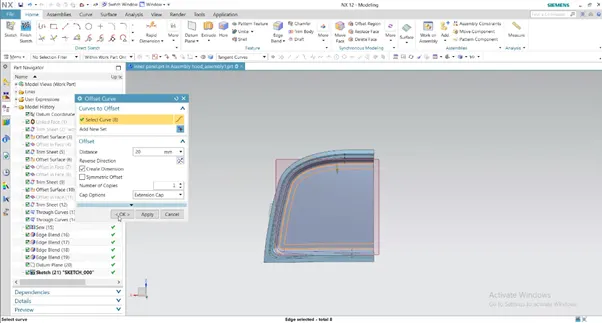
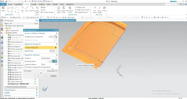
Now leave some surface in corners for hinge and project the curve
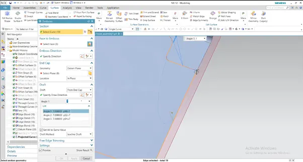
Now go to emboss and apply emboss make sure to give draft angle in sheet metal minimum draft should be 7mm (Draft should be positive so it is easy to manufacture)
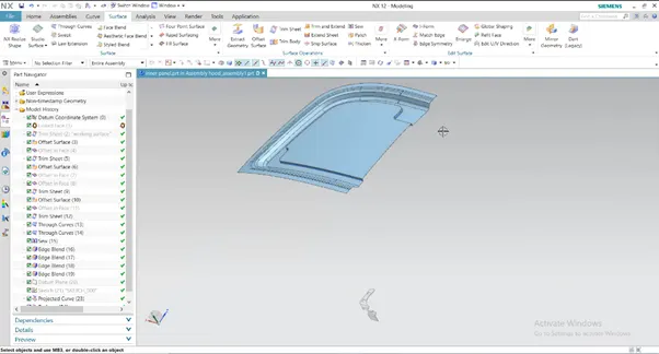
We have our emboss
Now make some sketches on datum plane and project it on surface and create emboss. Also, in sheet metal there should not be any sharp corners so we have to apply a blend over there. So, lets draw a sketch and make emboss there and apply blend on corners.
Similarly make some sketch for striker and hinges and blends over there and mirror the geometry
Apply the corner relief as 3mm (given)
After applying all these things we have inner panel almost ready
Just mirror the assembly using associate mirror
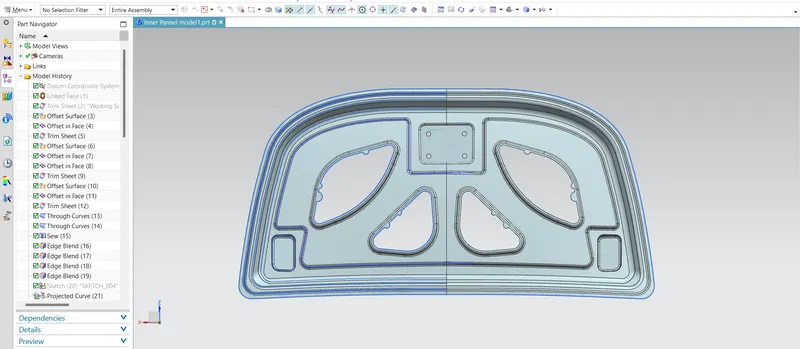
We are created emoboss for hinge assembly and latch striker so we can easily mount our assembly on it. once emboss is done we applied edge blend after sew operation. edge blend removes the sharp edges from emboss.
Now lest spme work on inner panel for hemming operation
Hemming is nothing but joining the the two sheet with bending one sheet over another sheet
Once hemming is done make assembly
We can applied assembly constraints and applying hinge assembly on inner panel
Initially fix the hood outer panel, and hood outer panel so they cant change their position when we apply constarints to other parts
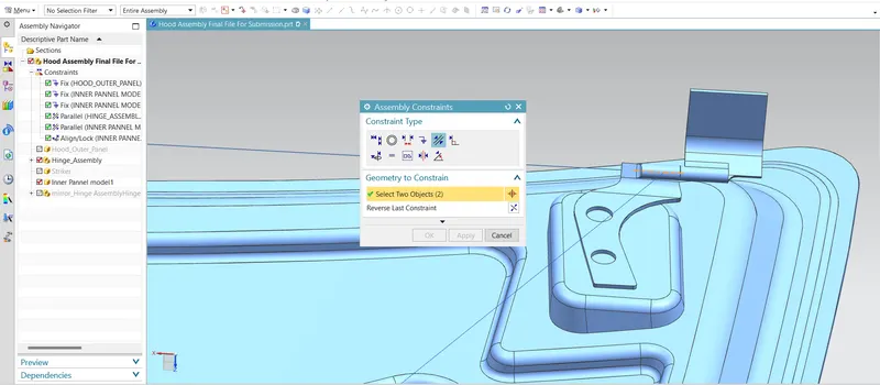
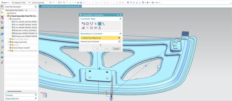
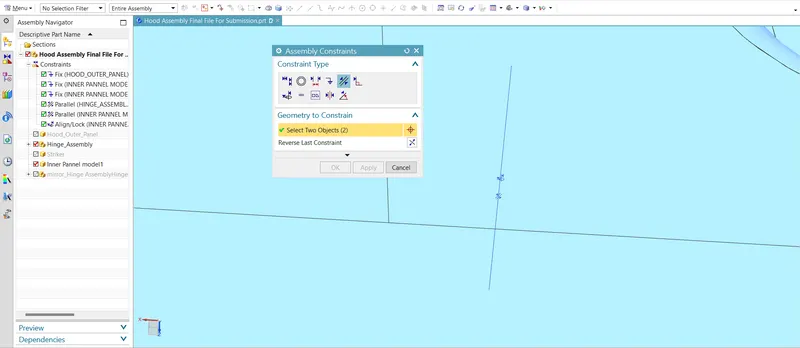
One the constraints is done just mirror the hinge assembly with associate mirror so the constraints also get mirror
Creating a circular trajectory for striker
circular trajectory is creating some angle for opning and closing of hood
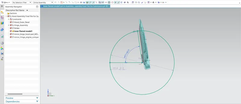
Now trajectory is complete now applied constraints between striker and inner panel
Once this done just applied thicken for sheet metal 0.7mm thickness is considered for thicken
Once thicken applied hide other features and shw thiken only.
do some visual inspection for any erros in curves, emboss, or constarints and finally save the model
Now make some visual changes for colors to apply render
Lets hide constraints, sketches and take some screenshots
Isometric view
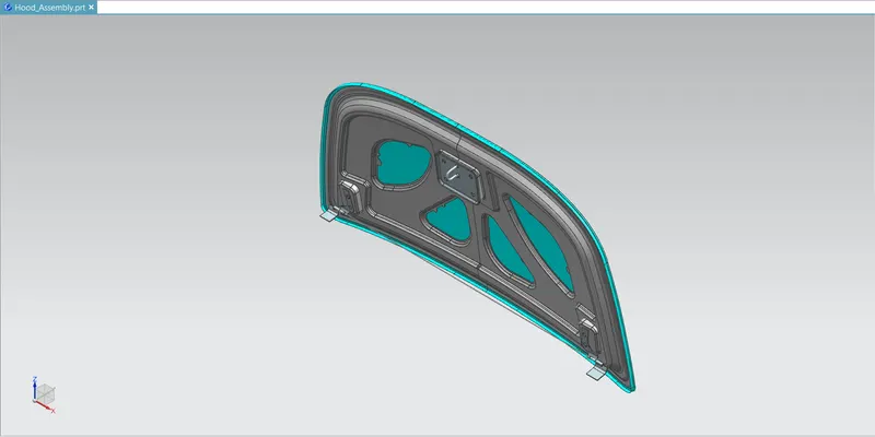
Front view
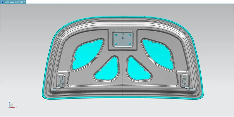
Left Side View
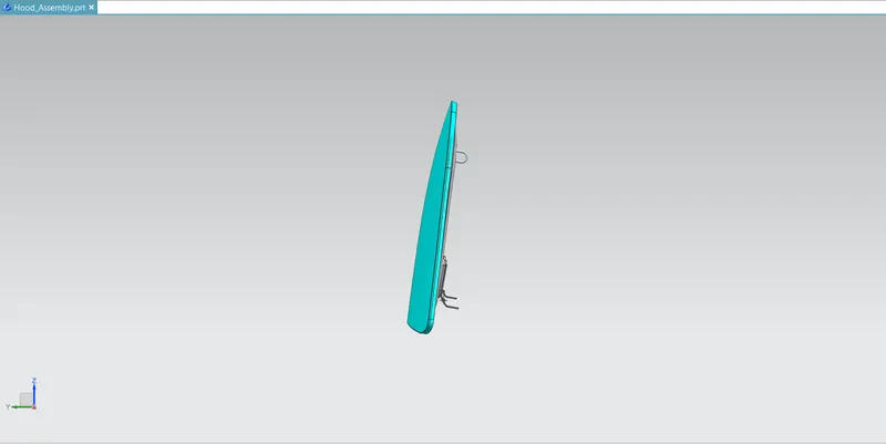
Right Side View
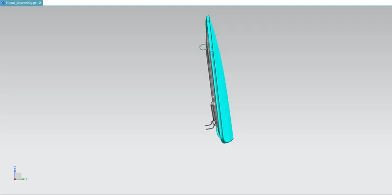
Top View
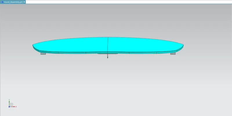
Bottom View
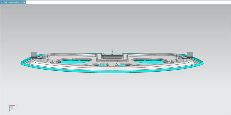
Trimetric view
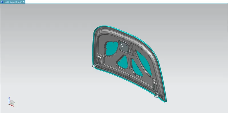
section View
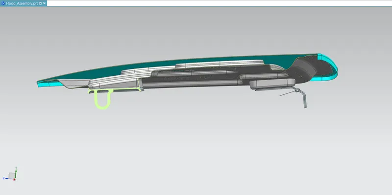
Render Images