Hood design-Week 2
Hood:
A car hood also referred to as a bonnet in some other countries is the hinged cover that rests over the engine of a front-engine vehicle. Its purpose is to cover the engine and other machinery parts. Car hoods are typically constructed from steel and sometimes from aluminum.
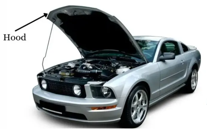
A supporting rod is inside the compartment to support the hood in an open condition. In the higher-end model, because of the heavy weight of the hood user cannot able to lift the hood. so that the supporting rod is replaced by a gas stay. One end of the supporting rod or gas stay is connected to the vehicle body and another end is connected to the hood.

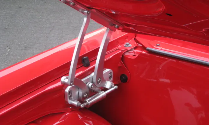
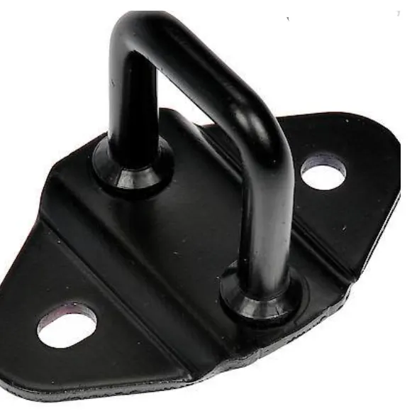
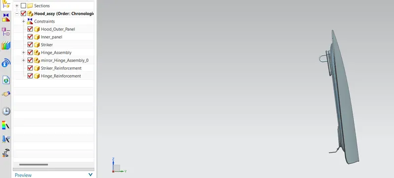
The hood consists of hinges which are for rotational movement and a striker for locking purposes.

Design process:
Using the master section and class A surface input, going to create the hood part of the car.
Defining Tooling Direction:
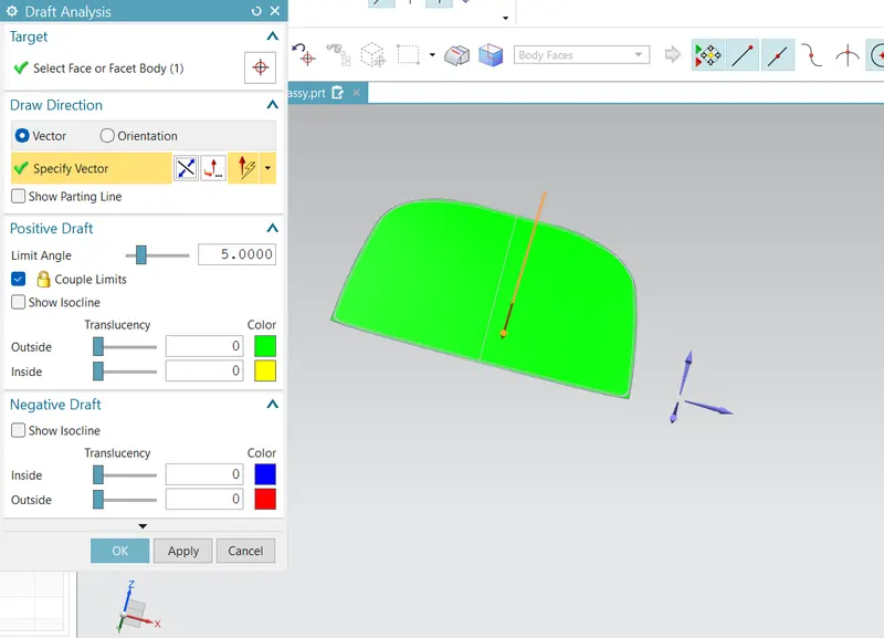
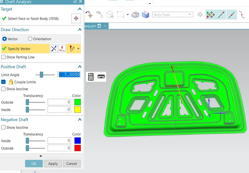
Here the panel is symmetry about a plane. Drawing a line between the corners and creating another line that is perpendicular to the previous line. Now check that the defined tooling axis is clearing the operations or not with help of the draft analysis option.
Inside hood panel:
Offset the given Class A surface as per the master section and created inside hood panel.
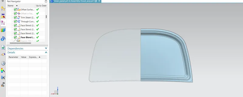
Next step is to create embossing
Embossing:
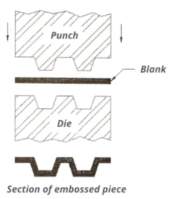
Sheetmetal embossing is a metal forming operation in which the sheet is stretched into a shallow depression. Embossing is generally used to make dimples on sheet metal to increase their rigidity on panels in houses or other places.
Deep drawing:
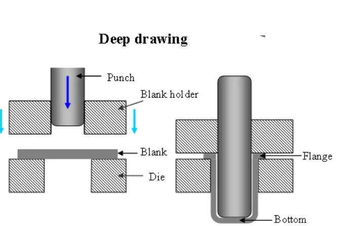
Deep drawing is a sheet metal process in which a sheet metal blank is radially drawn into a forming die by the mechanical action of a punch.
It is thus a shape transformation process with material retention. The process is considered "deep" drawing when the depth of the drawn part exceeds its diameter.
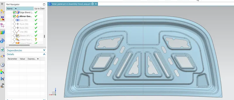
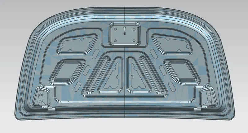
Here the embossing is created at a cross position because when the car hits on any object the impact force will affect the people inside the car. To reduce the impact, such cross-way embossing is done on this model. It dissipates the impact force outwards the body so that people inside the car experience very less impact force. While embossing a minimum draft angle of 7 deg should be maintained to eject the workpiece and tool without damage.
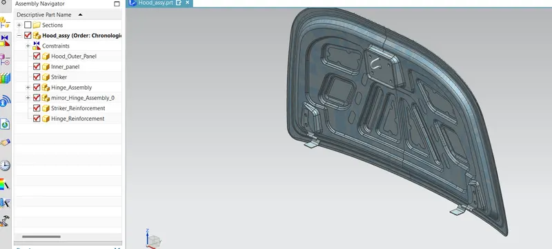
After this, the hinge and striker components are to be assembled with the inside hood panel.
To position the striker's location a circle is drawn using the hinge axis as the center point. The Striker pin axis should be perpendicular to the hinge axis. In that situation, only the striker will align properly.
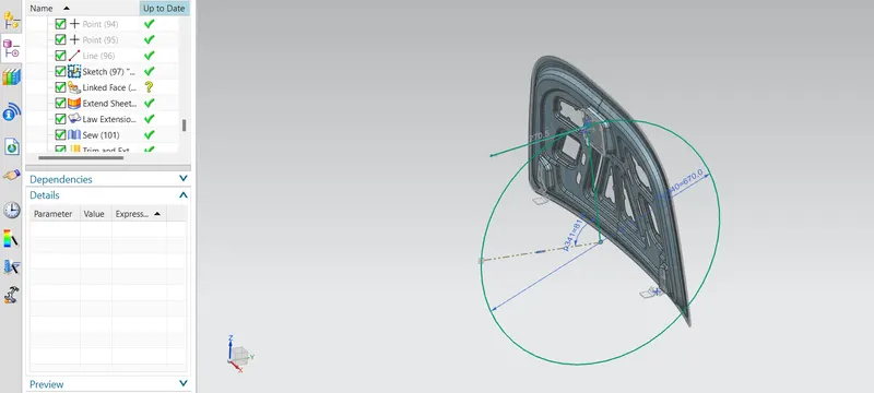
After that reinforcement were created for the hinge and striker.
Reinforcement:
Reinforcement means adding additional thickened parts to improve the strength of the component.
Here striker and hinges are going to be assembled with the inner panel. so some of the strength was reduced by those components. To improve the strength of those weakened face parts an additional thickened part is used on those places.
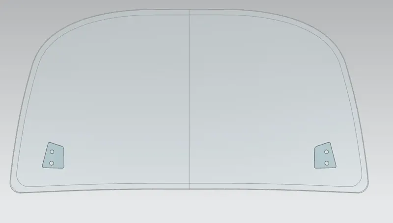
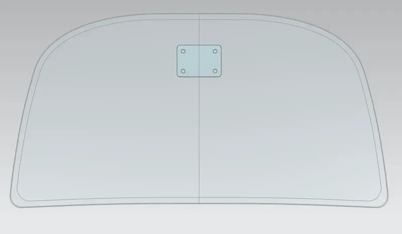
After that, the outer panel is attached with the inner panel using the hemming process.
Hemming:
Hemming is a forming operation in which the edges of the sheet are folded or folded over another part in order to achieve a tight fit. Normally hemming operations are used to connect parts together, to improve the appearance of a part and reinforce part edges.
The accuracy of the hemming operation is very important since it affects the appearance of the surface and surface quality. Material deformations, which occur during the hemming process, can lead to dimensional variations and other defects in parts.
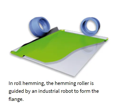
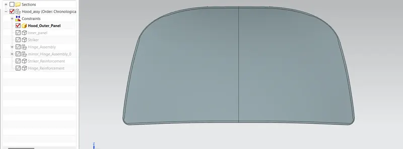
The corner part of the hemming is reduced to a distance because at the corner position if the hemming rollers rotate several times it will create some marks. This will reduce the aesthetic look of the car.
Draft analysis:
Draft analysis after completed part. Here all the surfaces are shown in green color so the part can able produced with the draft angle of 7 deg.
Section modulus:
The section modulus of the cross-sectional shape is of significant importance in designing beams. It is a direct measure of the strength of the beam. A beam that has a larger section modulus than another will be stronger and capable of supporting greater loads.
Z=I/Y, Z- section modulus, I- Moment of Inertia, y- Distance of outer fibre from the neutral axis.
Moment of Inertia (Second moment of area):
The Second moment of area is also called a moment of inertia. It is directly related to the area of material in the cross-section and the displacement of that area from the centroid. Once the centroid is identified, the important property of shape can be calculated. The axis that determines the centroid is known as the Neutral axis.
The second moment of area is a measure of the efficiency of a shape to resist bending caused by loading. A beam tends to change its shape when loaded. The second moment of area is a measure of a shape's resistance to change.
Bending stress equation:
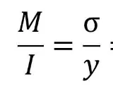
M= Bending moment
σ= Bending Stress
Bending moment:
A bending moment is the reaction induced in a structural element when an external force or moment is applied to the element.
Case 1:
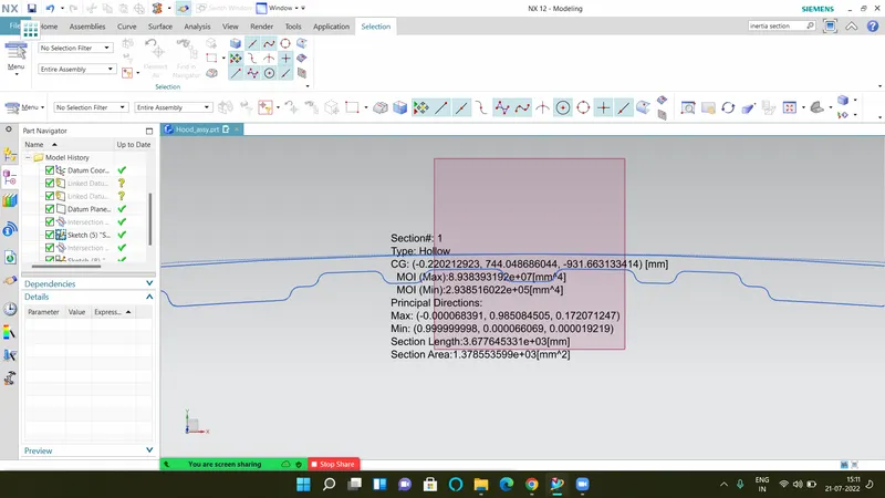
In the case-1 condition, the moment of inertia value is Imin is 2.938516022e+05 mm^4. If the moment of inertia value increases, section modulus will increase which increases the strength of the component.
Case:2
Just increased the bottom sketch by 0.5mm offset value and checked section modulus value.
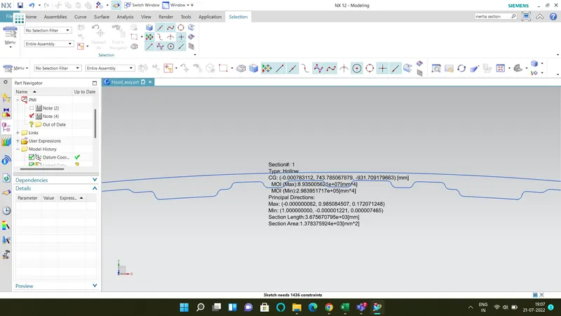
In this case-2 condition, the moment of inertia value is Imin is 2.983951717+05 mm^4. The value is increased from the previous model so that section modulus also increased and the strength of the component is increased from the previous model.