Design and Development of Hood Using NX CAD
DESIGN AND DEVELOPMENT OF HOOD (BIW) AND ITS ASSEMBLY USING NX CAD
OBJECTIVE:
The main objective of this report is to explain the parameters, standards and procedures followed in design and development of hood and its assembly. Then to explain the details about its manufacturing process followed by the OEM’s and the automotive industries.
DESCRIPTION:
Hood:
The hood (American English) or bonnet (common wealth English) is the hinged cover over the engine of motor vehicles. Hoods can open to allow access to the engine compartment, or trunk on rear-engine and some mid-engine vehicles for maintenance and repair. Car hoods are typically constructed from steel and sometimes from aluminium or usually made from the same material as the rest of the body.
The components associated with hood are,
- Outer panel
- Inner panel
- Hinges
- Latch & striker
- Prop(support) rod / Gas stay.
Design Parameters:
For this project, the design parameters are already given to complete the design and development of hood. Those parameters are as follows,
Hood Thickness Information
- Outer Panel Thickness = 0.75mm
- Inner Panel Thickness = 0.75mm
- Reinforcement Thickness = 1.5mm
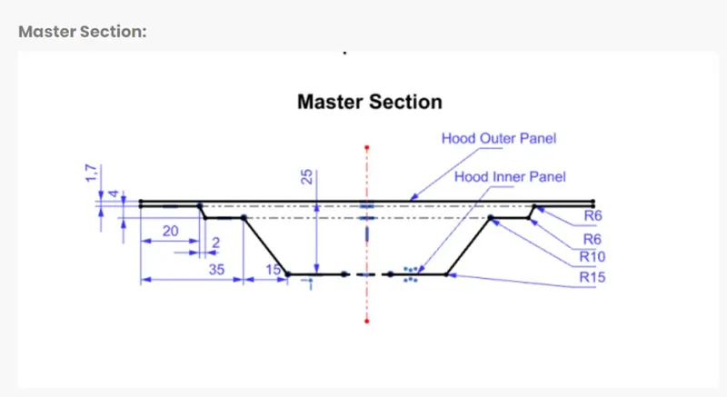
Master Section:
Master sections are the guides for design requirements which decide the component packaging after technical (Styling, Concept or Class-A) surfaces. Concept development in BIW.
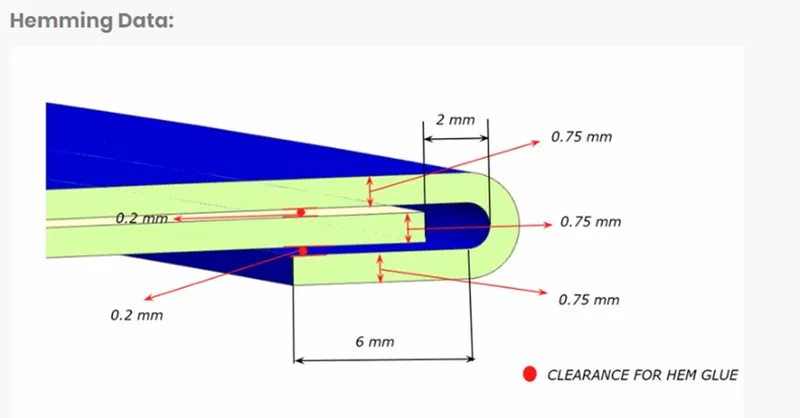
Hemming Data:
Hemming is a technology used in the automotive industry to join inner and outer closure panels together (hoods, doors, tailgates, etc.).
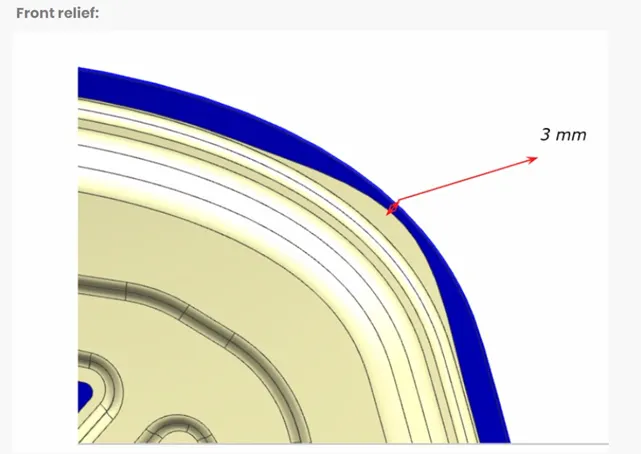
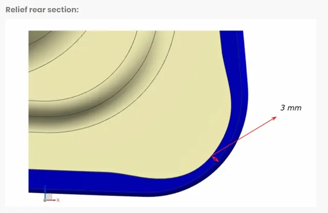
Hemming reliefs:
Design standards:
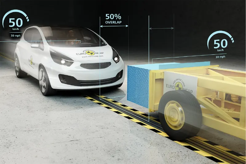
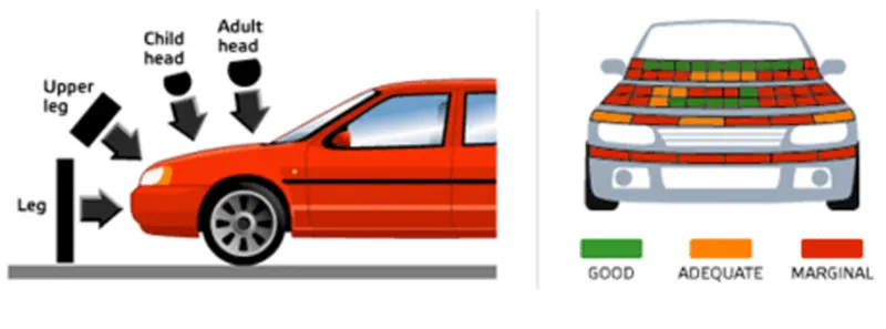
The standards for design are depends upon the country or region were the vehicles going to be used or operated and the assessment program followed in that particular region for the safety of pedestrians and passengers. The assessment programs currently followed by the OEMs are Euro NCAP and Japanese NCAP.
For this project, the Euro NCAP standards is considered for the hood design. The hood design is assessed to satisfy the needs of occupant’s protection while frontal crash and pedestrians protection.
The occupant’s protection considers adult and child occupant safety while the vehicle is heavily impacted in frontal crash. To satisfy the safety needs, hood design is capable of observing and diverting the impact force before it reaches the passenger compartment.
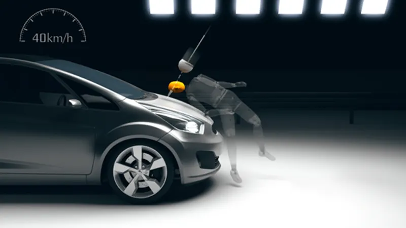
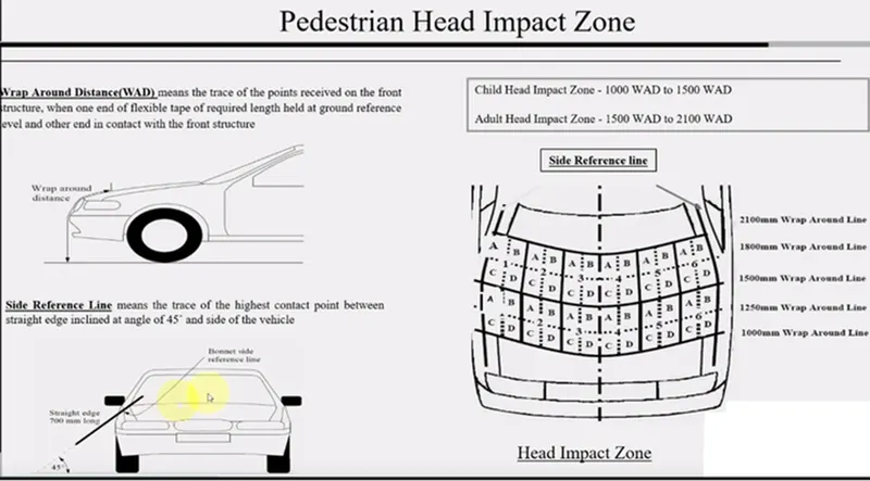
The pedestrian protection considers impact zone in various aspects like head impact zone and leg impact zone. Out of this head impact zone is very important in hood design. The head impact zone considers adult head impact and child head impact zones to satisfy the safety needs. The adult head impact zone is where the head of an adult comes into contact with the vehicle in a sudden collision and the region where the child head comes into contact with the vehicle in a sudden collision is said to be the child head impact zone. The designer should consider these zones while designing the hood and that design will allow the hood to easily deform when the collision happens to avoid severe injury of pedestrians.
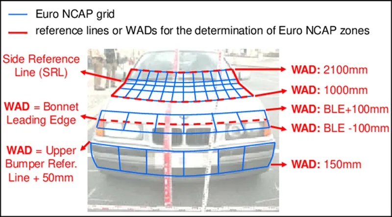
Those zones are specified with the help of wrap around distance (WAD). Wrap Around Distance (WAD) means the geometric trace described on the outer surface of the vehicle front structure by one end of a flexible tape, when it is held in a vertical longitudinal plane of the vehicle and traversed across the front structure. The tape is held taut throughout the operation with one end held at the same level as the ground reference plane, vertically below the front face of the bumper and the other end held in contact with the front structure.
Design procedure:
The following procedures are followed to design the hood according to the OEM standards. The design starts with the styling class A or skin data of the hood which is given by the styling team.
1.Inner panel:
Inner panel of the hood provides strength to the hood and provides the reinforcements for rod / gas stay, hinges and latch & striker which are all used to attach the hood with the engine compartment.
- The outer surface of hood skin data is given by the styling team. With that skin data the design process of inner panel starts.
- Datum co-ordinate system were created for plane references and the surface is offset to 0mm initially.
- This offset surface is taken as the working surface and it is trimmed along the yz plane.
- Then using the given master section, the trimmed surface is offset to further and further to the required dimensions.
- After offsetting those surfaces, the required curves were offset on the surface faces and new sketches were created to according to the requirements.
- With the help of these curves and sketches, those surfaces were trimmed and joined using the commands like through curve, law extension and trim & extend etc...
- Then the “emboss” were created using the new sketches created in the required planes, through the commands like emboss and law extension etc. with required drafts in the positive direction.
- After creating the embosses, unwanted materials are removed to reduce the weight and the surface for “mastic sealants” were created with the help of sketches and commands.
- Then the edges and corners were blended using the commands like face blend and edge blend to avoid the sharp edges and corners.
- The emboss for hinges and striker were created with the reference taken from the other parts using the command like wave geometry linker, datum plane, emboss and law extension etc.
- After creating required embosses and mastic points, the whole surface is mirrored about yz plane and sewed together to complete the hood inner panel surface.
- When the inner panel is completed, then it is thickened according to the design parameters of 0.75mm to create the inner panel.
- Then the “latch trajectory” were created with the help of hinge axis which used to assemble the striker in the future.
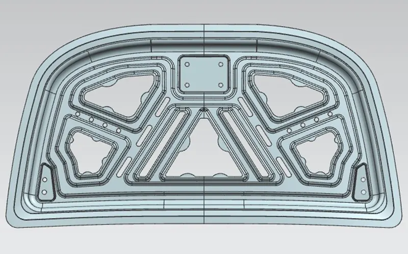
Back view of inner panel is shown.
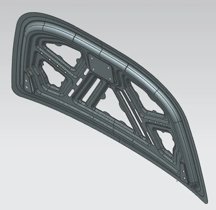
Isometric view of inner panel is shown.
Emboss:
To mould or carve (a decoration or design) on (a surface) so that it is raised above the surface in low relief is called as emboss. This emboss is designed to divert the force which is created during a sudden impact or collision from getting towards the passenger compartment into sideways towards the hinges. This diversion is necessary according to safety regulations of the passengers and the pedestrians.
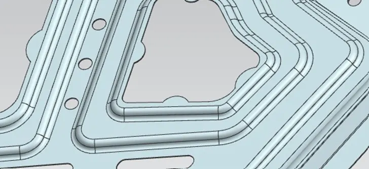
Embosses is shown.
Mastic Data:
Mastic sealants are the materials which is like a rubber or sponge used to seal the gap between the hood inner and outer panels to avoid NVH and improve strength to the outer panel. This mastic sealants are placed in the hood inner panel and the points where the sealants placed are called mastic points. Each mastic sealants covers 80mm diameter of space to serve its purpose. These mastic points are said to be the mastic data.
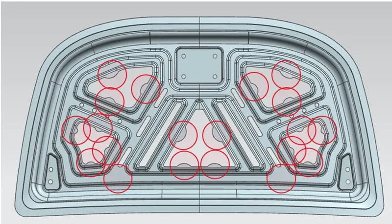
Mastic data is shown.
Latch Trajectory:
Latch trajectory is the path which decides the striker movement when the hood is opened/closed. This trajectory is created with the help of hinge rotation axis. With reference to the hinge axis a circle is drawn with required dimension and then a tangent line is created which is perpendicular to the reinforcement. This line and circle is said to be the latch trajectory.
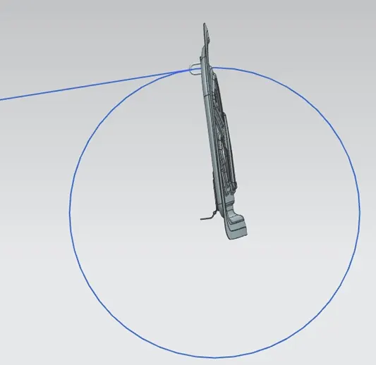
Latch trajectory is shown.
2.Outer panel:
Outer panel is just a metal cover is used to cover the inner panel and acts as an aesthetic part of the hood.
- The outer surface of hood skin data is given by the styling team. With that skin data the design process of outer panel starts.
- Datum co-ordinate system were created for plane references and the surface is offset to 0mm initially.
- This offset surface is taken as the working surface and it is trimmed along the yz plane.
- Then that surface is offset to required distance in downwards to create the hemming surface.
- With the help of ‘offset curve on face’ command, the edge curve is offset to 2mm inwards and then the surface is trimmed with this curve to create the glue gap between the outer and inner panel.
- Then the newly created surface edge curve is further offset to required dimension and the law extension command is applied to this curve to create the third surface.
- After creating three surfaces, the unwanted regions were trimmed to connect the three faces to form the hemming flange with face blend command.
- Hemming relief at the corners were created using the newly created sketch according to the given parameters.
- Then the surface is mirrored about the yz plane and sewed together to form the outer panel surface.
- This outer panel surface is thickened to form the final outer panel which is hemmed with the inner panel.
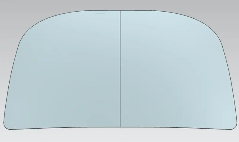
Back view of outer panel is shown.
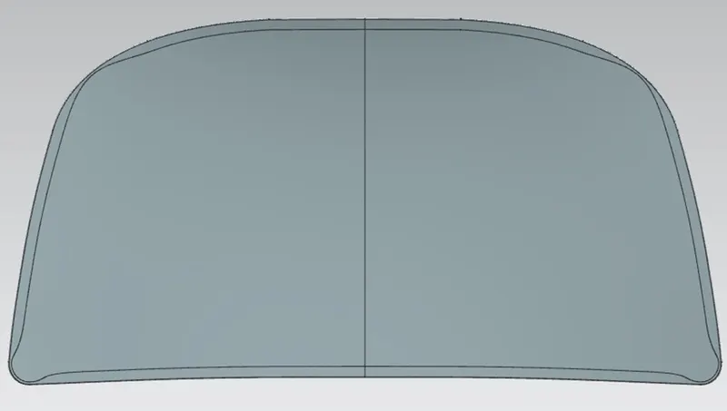
Front view of outer panel is shown.
3.Hinges:
A hinge is a mechanical bearing that connects two solid objects, typically allowing only a limited angle of rotation between them. Two objects connected by an ideal hinge rotate relative to each other about a fixed axis of rotation, all other translations or rotations being prevented, and thus a hinge has one degree of freedom. Hinges may be made of flexible material or of moving components.
For this project, the hinge part file is already given.
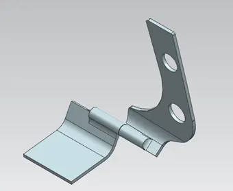
Hinge assembly is shown.
4.Latch & striker:
Latch and striker are the parts which is used to lock or hold the hood with the engine compartment in a secured position.
Latch has a housing having a mouth. A rachet is pivotally mounted within the housing to co-operate with the mouth to pivot between an open, a secondary closed and a primary closed condition for receiving, engaging and cinching a keeper of a striker. Latch is mounted on the engine compartment.
Striker has a clamp with reinforcement is attached with the hood. This striker is locked by the latch mechanism to hold the hood in secured position while the car is in motion or moving in a certain speed and to avoid NVH.
For this project, the striker part file is already given.
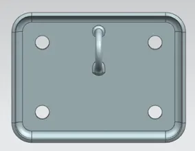
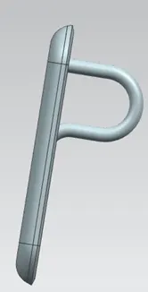
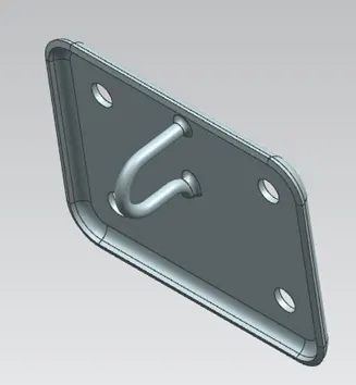
Front, side and isometric views of striker is shown.
5.Prop rod / Gas stay:
Prop rod: hood prop rods are stable rods intended to safely hold up vehicle hoods during inspection and repairs.
Gas stay: a gas strut (also referred to as a gas spring) is a spring that operates due to the force exerted by the compressed gas (usually nitrogen) stored inside the cylinder. Luxury carmakers provide gas strut/stay to lift the hood and hold it in place.
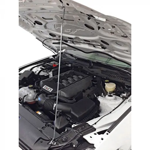
Prop rod (support rod) is shown.
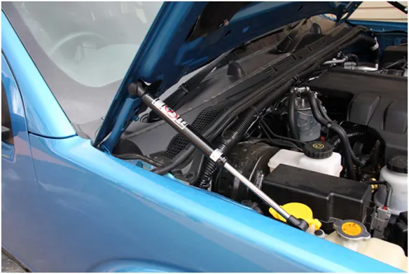
Gas stay is shown.
Reinforcement:
Reinforcements are the parts used to improve strength in the weaker region of hood like the regions where the hinges and strikers going to be assembled with nut and bolts. It also reduces the NVH (noise vibration hardness) of the hood. The reinforcements of hood are created with a thickness of 1.5mm according to the design parameters.
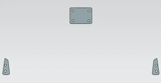
Reinforcements for hinges and striker is shown.
Draft analysis:
Draft analysis is used to find the feasibility to manufacture the deigned part using the deep drawing process. It is carried out with help of datum CSYS created normal to the surface to check draft angle. For this hood design the minimum draft of 5⁰ is maintained and the draft analysis is carried out and the design is passed in the draft analysis.
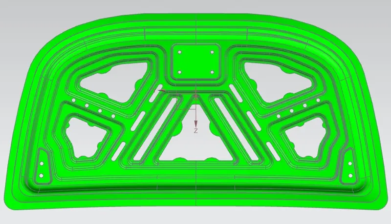
Draft analysed part is shown.
Assembly of hood components:
The new part file is created in the assembly window to start the assembly of hood components. The separate part files which are created before for inner panel, outer panel, hinge and striker is opened one by one in the assembly window with the help of insert part command.
- After inserting the parts, hood outer panel and inner panel is fixed with help of the assembly constraints, here the fix constraint is applied.
- Then hinge assembly xz plane and xz plane of the datum co-ordinate system in assembly window is applied with the parallel constraint and the surface of hinge and the emboss created for hinge in the inner panel is applied with touch constraint to assemble.
- With help of mirror assembly command, the hinge assembly is mirrored about the yz plane to copy and the paste the hinge assembly in the left side.
- A line is created in the centre of striker and the tangent point in the latch trajectory is applied with the touch constraint and the datum plane created in the striker is applied with touch constraint to the yz plane of datum CSYS in the assembly window.
- Finally, striker back surface and the emboss surface for striker in the inner panel is applied with touch constraint to complete the hood assembly.
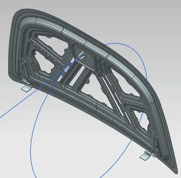
Isometric view of hood assembly is shown.

Sectioned view after assembly is shown.
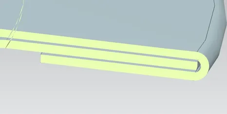
Hemming clearance is shown.
Commands used:
- Datum co-ordinate system: - with a datum CSYS, objects are created relative to some aspect of the datum object, such as a point, plane or axis. The datum CSYS contains 3 datum planes and 3 datum axes along with a co-ordinate system.
- Offset surface: - to create an offset of one or more existing faces. The result is a new body (or bodies) with an offset relation to the chosen faces.
- Offset curve in face: - to create offset curves on one or more faces from connected edges or curves on the surfaces. The offset curves can be associative or non- associative, and lie at a specified distance from an existing curve or edge section.
- Trim sheet: - used to trim off a portion of a sheet body using curves, faces or datum planes.
- Through curves: - used to create a body through multiple sections where the shape changes to pass through each section. Sections are curves, points, solid edges and solid faces.
- Law extension: - to extend an existing surface or sheet based on the laws for distance and the angle of the extension. Law extension creates flanges or extensions when a particular direction is important or when it is necessary to reference the existing face.
- Trim and extend: - this option lets you extend and trim one or more surfaces using a set of tool objects composed of edges or surfaces.
- Face blend: - to provide a dedicated type for blending along intersection edges of bodies combined with a Boolean feature. Face blend is primarily used to blend between faces of separate bodies. It can also be used to blend between faces of a single body.
- Edge blend: - lets you add points and set radius values along edges in an edge set.
- Sketch: - used to create 2D sketches along the required plane.
- Projected curve: - to project curves, edges, or points that are external to the sketch, onto the sketch along the normal of the sketch plane.
- Emboss: - use to create an embossing by modify a body with faces made by projecting a section along a vector, with options for end cap location and shape.
- Trim body: - to trim one or more target bodies using a face or plane. You can specify the portion of the body to retain and the portion to discard. The target bodies take the shape of the trimming geometry. You must select at least one target body.
- Datum plane: - to create a planar reference feature to help define other features, such as swept bodies and features at angles to the faces of target solids.
- Wave geometry linker: - it allows the designer to reference existing part geometry when designing a new part in existing assemblies.
- Extend sheet: - it uses a value for an offset value to extend/shorten the sheet.
- Mirror geometry: - is the command, copies and pastes bodies on the model by mirroring through plane or surface.
- Sew: - to join two or more sheet bodies into a new single sheet body.
- Thicken: - to offset one or more connected faces or sheets into a solid body.
- Extract body: - to create an associative body by extracting faces from another body.
- Assembly constraints: - assembly driven constraints provide you with a way to control the range of motion both linear and angular for the components of an assembly.
- Move component: - you can change position, the direction of the components in assembly by the “move component” command.
- Mirror assembly: - used to mirror the assembly about the specified plane.
Manufacturing process:
The OEMs and automotive industry commonly use the manufacturing processes like,
- Deep-drawing and
- Hemming.
Deep-drawing:
Deep-drawing is a sheet metal forming process in which a sheet metal blank is radially drawn into a forming die by the mechanical action of a punch. It is thus a shape transformation process with material retention. The process is considered “deep” drawing when the depth of the drawn part exceeds its diameter. This is achieved by redrawing the part through a series of dies. The flange region (sheet metal in the die shoulder area) experience a radial drawing stress and a tangential compressive stress due to the material retention property. These compressive stresses (hoop stresses) result in flange wrinkles. Wrinkles can be prevented by using a blank holder, the function of which is to facilitate controlled material flow into the die radius.
Deep drawing has been classified into conventional and unconventional deep drawing. The main aim of any unconventional deep drawing process is to extend the formability limits of the process. Some of the unconventional processes include hydromechanical deep drawing, hydroform process, aquadraw process, Guerin process, marform process and the hydraulic deep drawing process to name a few.
Industrial uses of deep drawing processes include automotive body and structural parts, aircraft components, utensils and white goods. Complex parts are normally formed using progressive dies in a single forming press or by using a press line.
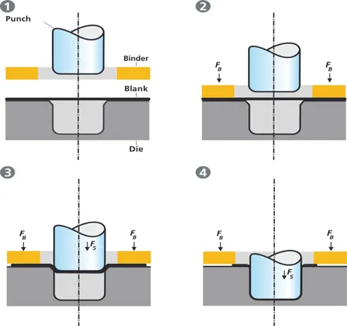
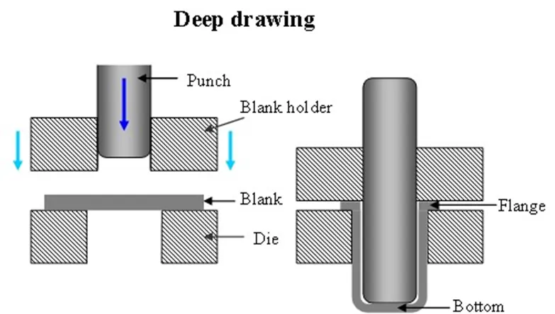
Working materials and power requirements:
Softer materials are much easier to deform and therefore require less force to draw. The following is a table demonstrating the draw force to percent reduction of commonly used materials.
|
Drawing force required for various materials and reductions [kN] |
|||||
|
Material |
Percent reduction |
||||
|
39% |
43% |
47% |
50% |
||
|
Aluminium |
88 |
101 |
113 |
126 |
|
|
Brass |
117 |
134 |
151 |
168 |
|
|
Cold-rolled steel |
127 |
145 |
163 |
181 |
|
|
Stainless steel |
166 |
190 |
214 |
238 |
|
Tool materials:
Punches and dies are typically made of tool steel, however cheaper (but softer) carbon steel is sometimes used in less severe applications. It is also common to see cemented carbides used where high wear and abrasive resistance is present. Alloy steels are normally used for the ejector system to kick the part out and in durable and heat resistant blank holders.
Lubrication and cooling:
Lubricants are used to reduce friction between the working material and the punch and die. They also aid in removing the parts from the punch. Some examples of lubricants used in drawing operations are heavy-duty emulsions, phosphate, white lead and wax films. Plastic films covering both sides of the part while used with a lubricant will leave the part with a fine surface.
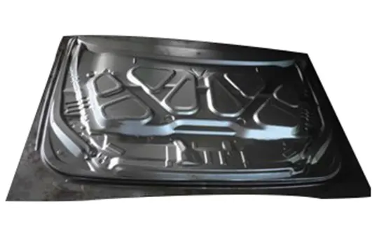
Deep drawn hood inner panel.
Hemming:
Hemming is a forming operation in which the edges of the sheet are folded or folded over another part in order to achieve a tight fit. Normally hemming operations are used to connect parts together, to improve the appearance of a part and to reinforce part edges.
In car part production, hemming is used in assembly as a secondary operation after deep drawing, trimming and flanging operations to join two sheet metal parts (outer and inner) together. Typical parts for this type of assembly are hoods, doors, trunk lids and fenders.
The accuracy of the hemming operation is very important since it affects the appearance of the surface and surface quantity. Material deformations, which occur during the hemming process, can lead to dimensional variations and other defects in parts. Typical hemming defects are splits or wrinkles in the flange, material overlaps in the corner areas or material roll-in. This is why it is important to use simulation tools in order to, on the other hand, significantly reduce the number of “trial and error” loops during try-out and production.
There are various types of hemming operations:
- Conventional die hemming
- Roll hemming.
Conventional die hemming:
Conventional die hemming is suitable for mass production. In die hemming, the flange is folded over the entire length with a hemming tool. Normally the actual hemming is a result of a forming operation in which the flange is formed with a hemming tool after the drawing and trimming operations have been completed. The formed flange is then hemmed in several process steps. These steps include, for example, the pre-hemming and final hemming depending on the respective opening angle of the flange. Production plants for conventional die hemming are very expensive, but the cycle times are very low.
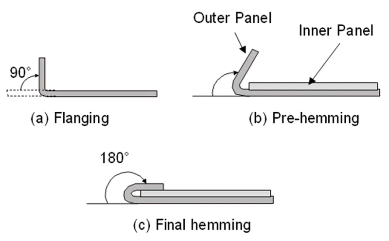
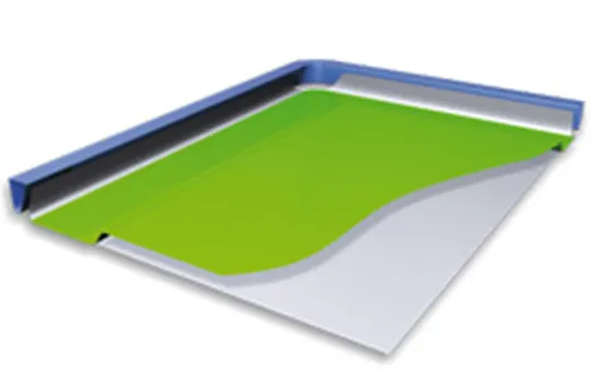
Conventional hemming is shown.
Roll hemming:
Roll hemming is carried out incrementally with a hemming roller. An industrial robot guides the hemming roller and forms the flange. Roll hemming operation can also be divided into several pre-hemming and final hemming process steps. Roll hemming is very flexible to use and tool costs are significantly lower as compared to those of conventional die hemming. However, the cycle times are much higher since the hemming is realized using a hemming roller which follows a defined path.
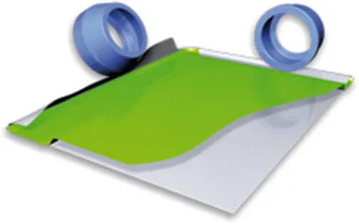
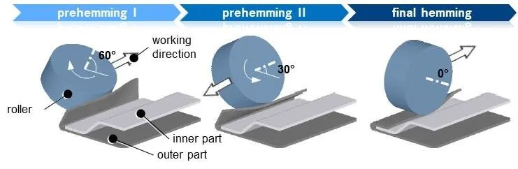
Roll hemming is shown.
CONCLUSION:
The parameters, standards, procedures and manufacturing process involved in design and development of hood and its assembly which is followed in the OEMs and automotive industries is explained in detail with reference images.