Hood design-Week 2
DESIGNING OF CAR ENGINE HOOD USING NX-CAD:-
OBJECTIVE:
To create an outer and inner hood panel, positioning the striker, hinge, and their reinforcements.
INTRODUCTION:
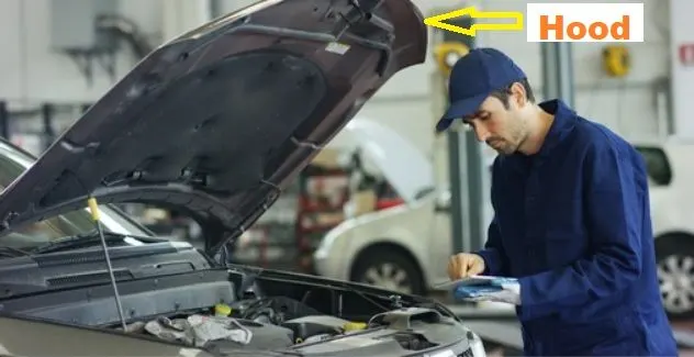
Hoods are the accessing areas for engine and other major components of the automotive. Some hoods are front flip opening
type which is much more ease of access. In this hood design project I have given with the styling outer panel of hood. By
using which the BIW (Body in White) hood part inner panel is designed using the master sketch available. After developing the
inner panel design, the embosses are given to the inner panel which adds stiffness, increases the strength locally and plays an
important role in force dispersion. Actually the hood design is influenced by many factors, initially the styling team develops
the styling panel/skin panel for the automotive and then we need to assess the technical design and manufacturing feasibility
of the product. The inner panel is defined using its opening angle, predefined master sketch, safety standards, wrap around
distance, hood side reference angle, etc. substantially. The inner panel consist of features like embosses, contour holes,
mastic sealant, reinforcements, land area etc. Hemming is done to fold the outer panel over the inner panel. The hinges were
placed on the sides of the hood. The latch and striker arrangement, an opening mechanism is positioned using the hinge axis
method.
SOFTWARE USED:
SIEMENS NX12
HOOD:
Hood are typically made out of steel or aluminum which are used to cover the front side of the car where the engine is to
be placed, although aftermarket manufacturers may manufacture hoods out of fiberglass, carbon fiber, or dry carbon.The hood
or bonnet is the hinged cover over the engine of motor vehicles that allows access to the engine compartment for
maintenance and repair. On passenger cars, a hood may be held down by a concealed latch.Some high performance cars have
‘hood scoops’ which channel outside air directly to the air filter, which gives improved performance and efficiency.It is hinged
thin sheet which covers and protects the main parts of car like engine.
Data to follow:
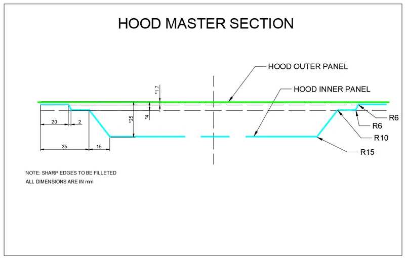
Data to be used:
Hood Thickness Information
- Outer Panel Thickness = 0.75mm
- Inner Panel Thickness = 0.75mm
- Reinforcement Thickness = 1.5mm
SAFETY CONSIDERATION WHILE DESIGN HOOD: -
Hood of engine design in such a way that reduces air effect and all the maintenance part easy to do and it should also
protect from the external disturbance on the engine. When the car comes to an accident it must be impact force and
distributed outside so it should be the Y-shape.
While designing Hood should take care of Safety, Quality, Styling, and manufacturing. The Most important safety
requirement to be considered while designing the Hood is pedestrian safety from collision from the front side. Pedestrian
safety, It’s a norm that provides a safety feature to the body when a car gets collides from the front side and reduces the
injuries to the body.
Safety is the most important criteria in automobile designs which concentrate on both pedestrian and occupant safety.
Pedestrians are the most vulnerable road users and are at high risk of traffic accidents. The major reason for the fatality of the
pedestrian in a traffic accident is due to the head injury resulting from the hard impact of the head against the stiffer hood or
the ground. This leads to the necessity of a new inner hood panel that is less stiff and pedestrian and pedestrian-friendly.
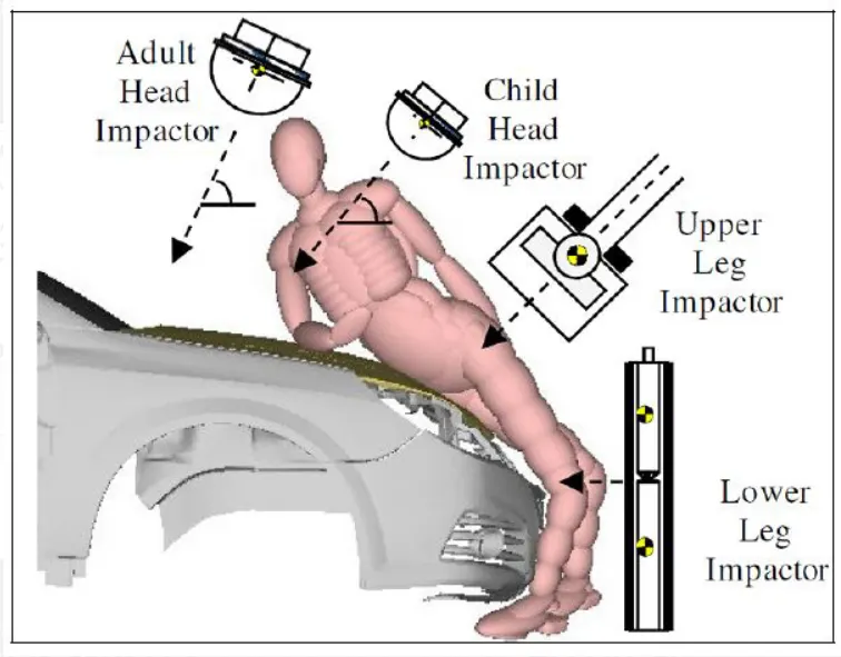
In this study, three kinds of sandwich hood structures are proposed for reducing pedestrian head injuries, including carbon
fiber-reinforced polycarbonate, carbon fiber-reinforced foam, and aluminum-reinforced polycarbonate.
The finite element method is used to simulate the impact between the vehicle's hood and the headform impactor. The
software used in the simulation is LS-DYNA. The results predicted by the headform-hood tests show that the hood structure
with aluminum-reinforced polycarbonate material provides enough absorption capability to protect pedestrians from the
impacts of accidents. It is also stiff enough to keep pedestrians' heads away from the inner parts of the engine cavity.
Child Head Impact:
Car-pedestrian accidents account for a considerable number of automobile accidents in industrialized countries. Head
injury continues to be more concerned with Automobile impacts. Because the head is the most seriously injured part in many
collisions including in pedestrian automobile collisions. To reduce the severity of such injuries international safety committee
have proposed subsystem tests in which head foam impactors are impacted upon the car hood
Currently in India, Automotive Indian Standard (AIS) 100, Amendment 1 is used to evaluate the performance of
vehicles against pedestrian safety. This standard has been harmonized from the international evaluation standard Global
Technical Regulation No. 9 (GTR 9), whose purpose is to bring about an improvement in the construction of the fronts of
vehicles and, in particular, those areas which have been most frequently identified as causing injury when in collision with a
pedestrian or other vulnerable road user. The tests required are focused on those elements of the child and adult body most
frequently identified as sustaining an injury, i.e. the adult head and leg and the child's head. To achieve the required
improvements in the construction of vehicles, the tests are designed in such a way that they will represent the rear world
accident scenario.
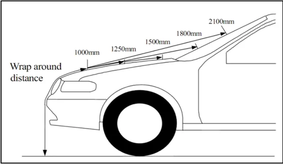
Wrap Around Distance (WAD):
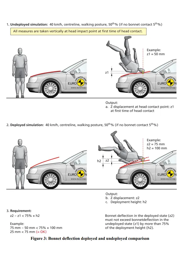
When a car crashes on the pedestrian, the whole human body wraps around the front shape of the car, and the head impacts
on the bonnet or the windscreen. The distance at which the head impacts on the car from the ground is mentioned as Wrap
Around Distance (WAD). To be specific the Wrap Around Distance is a measurement of the distance from the ground to the
head impact zone over the outer surface of the car. The wrap-around distance is measured longitudinally in the center of the
vehicle from the ground. The severity of the injury caused by the frontal crash depends on the type and shape of the vehicle,
the speed of the vehicle, and the movement of the pedestrian relative to the vehicle. In addition to these parameters, the
wrap-around distance plays a major role in the safety measures of a pedestrian,During the crash analysis, based on the Wrap
Around Distance(WAD), two test areas will be created namely the Child head impact zone and the Adult head impact zone.
The child head impact zone is between 1000 to 1700 mm WAD and the adult head impact zone ranges between 1700 to 2100
mm WAD.
Designing a Hood with a Master Sketch:
Components of a Hood:
- Hood outer panel
- Hood inner panel
- Latch and Striker
- Hinge engine compartment
- Hinge hood part
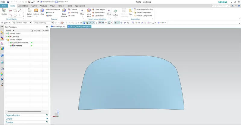
Hood outer panel:
The outer panel is nothing but the outer skin of the inner panel. Otherwise called as a cover of the inner
panel. It is the part, which gives luxurious look to the hood or bonnet. The outer panel and inner panel cannot join by any
welding process like spot welding or rivet, which spoil the outer look of a car.
Hood Inner panel:
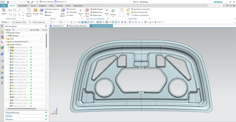
This study introduces a new method for decreasing the hood stiffness, by making a hole on the inner hood panel. To determine the most
effective hole position on the inner hood panel, the method of modal stiffness was employed, in an attempt to reduce the HIC from a collision
between a vehicle and a head-form impactor. FRF (frequency response function) results for the reference vehicle model on head-form impact
simulation were obtained. In addition, modal analysis of the entire vehicle model was simultaneously carried out. Subsequently, using the results
of these two analyses, dominant frequencies (41.7 Hz and 83.3 Hz) were obtained, which related to the deformation of the inner hood panel. Then,
adequate hole positions at each modal frequency were selected, and the inner hood panel was improved, by making a hole at these positions.
Finally, through head-form impact simulations on the improved vehicle model with the hole, it was demonstrated that the new method applied in
this study is acceptable and useful. In the case of the improved vehicle model with a 40 mm diameter hole on the inner hood panel, this showed a
significant reduction in the HIC of approximately 12.2%, compared to the original vehicle model.
Striker:
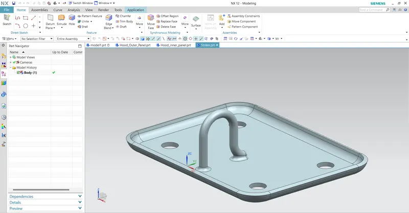
A latch or catch (called sneck in Northern England and Scotland) is a type of mechanical fastener that joins two (or more) objects or surfaces while
allowing for their regular separation. A latch typically engages another piece of hardware on the other mounting surface. Depending upon the type
and design of the latch, this engaging bit of hardware may be known as a strike. A latch is not the same as the locking mehanism of a door or
window, although often they are found together in the same product. Latches range in complexity from flexible one-piece flat springs of metal or
plastic, such as are used to keep blow-moulded plastic. power tool cases closed, to multi-point cammed latches used to keep large doors closed.
Hinge Reinforcement:
Devices for preventing movement between relatively-movable hinge parts for maintaining the hinge in two or more positions, e.g.
intermediate or fully open the maintaining means acting perpendicularly to the pivot axis with a coil spring perpendicular to the pivot axis specially
adapted for vehicles The present invention concerns a hinged door check, for vehicle doors, in particular, consisting of two hinged parts which are
connected swiveling around an axis of rotation by a hinge pin and which have a holding device integrated between them defining different relative
rotational positions.The hinge pin is connected detachable from the first hinged part by fasteners so that the hinged parts are separable when
unloosening the fasteners while keeping the connection between the hinge pin and the second hinged part and the holding device assigned to the
latter.
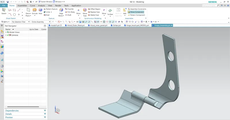
Position of Stiker and Hinge Reinforcement:
For the proper opening and closing of the hood, the striker should be perpendicular to the trajectory of the hood. For this, the hinge
is assembled at its position. Once it is placed, the hinge axis is drawn.
- To check the hinge axis as the center we draw a big circle to position the latch in such a way that it is perpendicular to the hood trajectory.
- In between the two hinges, the striker is perpendicular to the midpoint of the two hinges, Why because while closing and opening of the latch
and the striker the opening position be similar actions.
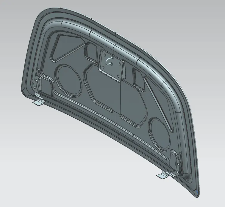
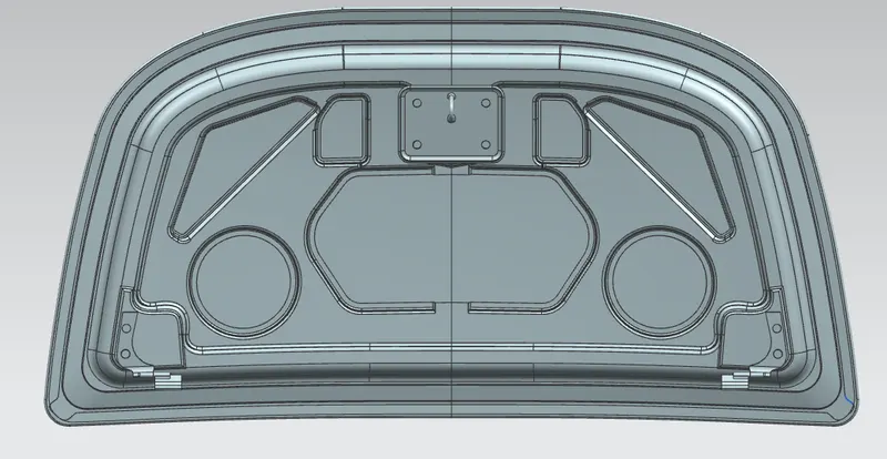
Striker & Hinge Reinforcement:
- Hinge:- It is used to mount the Hood into the desired position so that it can be easily can close and open when required.
- Striker:- It is mounted in the inner panel and provides a locking system.
Deep drawing:
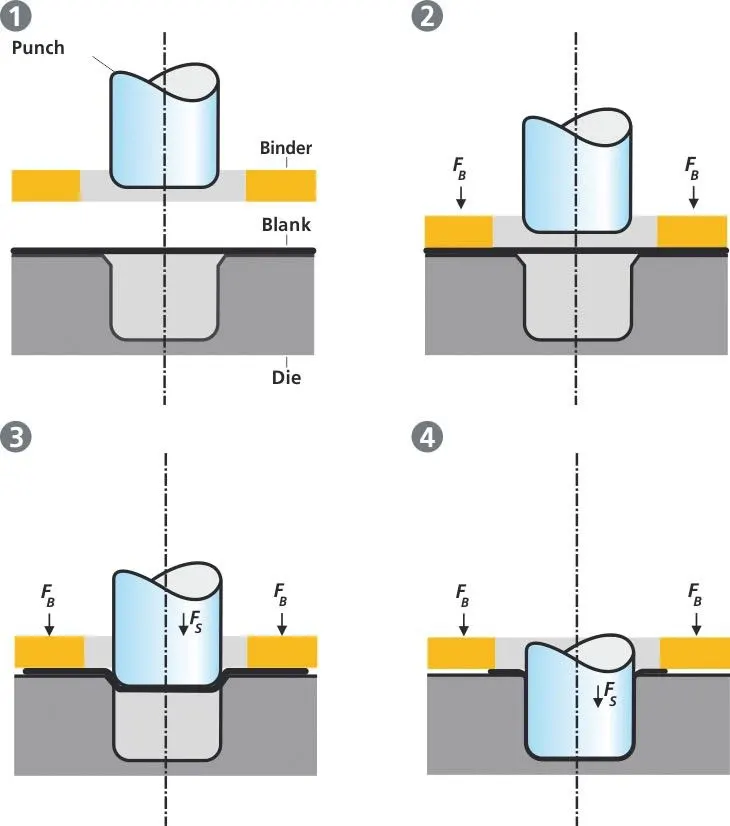
Deep drawing is a sheet metal forming process in which a sheet metal blank is radially drawn into a forming die by the mechanical
action of a punch. It is thus a shape transformation process with material retention. The process is considered a "deep" drawing when the depth of
the drawn part exceeds its diamete. We give a positive draft or an angle for a better drawing process.
Process definition:
The deep drawing process is a forming process that occurs under a combination of tensile and compressive conditions. A flat sheet metal
blank is formed into a hollow body open on one side or a hollow body is formed into a hollow body with a smaller cross-section. [DIN 8584]
Deep drawing processes are divided into three types:
- Deep drawing with tools
- Deep drawing with active means
- Deep drawing with active energy
In the automotive industry, deep drawing is usually carried out using rigid tools.
Emboss:
Embossing is a metal forming process for producing raised or sunken designs or relief in sheet material by means of matched male and female
roller dies, theoretically with no change in metal thickness, or bypassing sheet or a strip of metal between rolls of the desired pattern. The metal
sheet is drawn through the male and female roller dies producing a pattern or design on the metal sheet. Depending on the roller dies used,
different patterns can be produced on the metal sheet. Emboss should be in 7 degrees to 25-degree incline in angle and it should not be in 90-
degree angle, why because when we do stamping in manufacturing the stamping tool fits the sheet metal hence it will not come out of that sheet
metal, So this is the main reason why the emboss face is in angle.
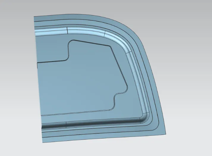
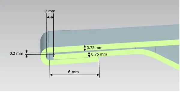
HEMMING PROCESS
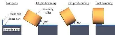
- Hemming is a forming operation in which the edges of the sheet are folded or folded over another part in order to achieve a tight fit.
Normally hemming operations are used to connect parts together, to improve the appearance of a part, and to reinforce part edges.
Conventional die hemming. - Hemming is the process in which the edge is rolled flush to itself, while a seam joins the edges of two materials. Normally hemming
operations are used to connect parts together, to improve the appearance of a part, and to reinforce part edges. In hood design, hemming is
used in assembly as a secondary operation after deep drawing, trimming, and flanging operations to join two sheet metal parts (outer and
inner) together. Dimensions of hemming are given below. - In between the outer panel and inner panel, there will be gluing after or before the hemming process because to reduce NVH and also
sticking the two panels.
Types of Hemming:
conventional die hemming:
In conventional die hemming, the flange is folded over the entire length with a hemming tool.
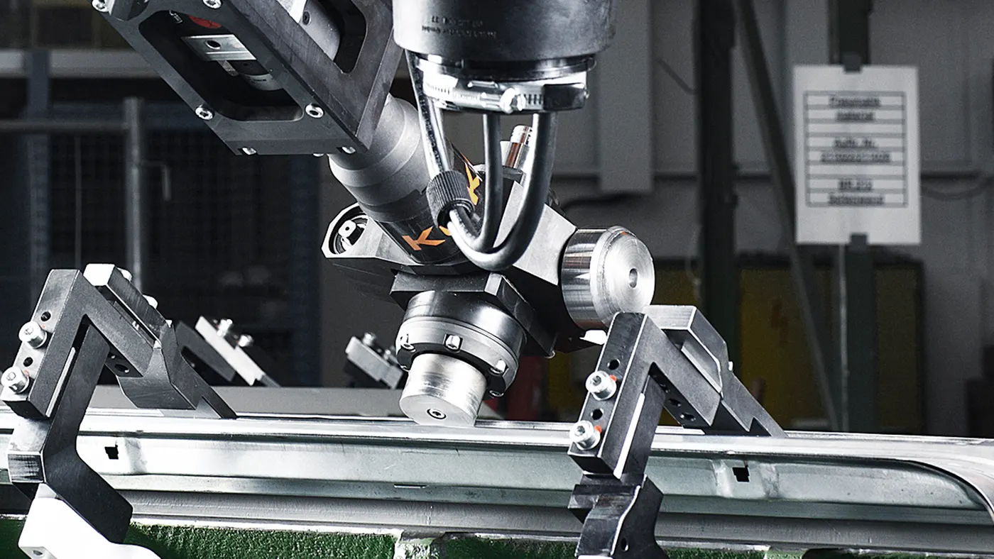
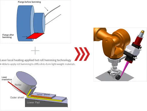
Roll hemming:
In roll hemming, the hemming roller is guided by an industrial robot to form the flange.
Hemming Parameters:
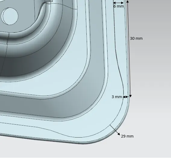
RELIEF CORNER:
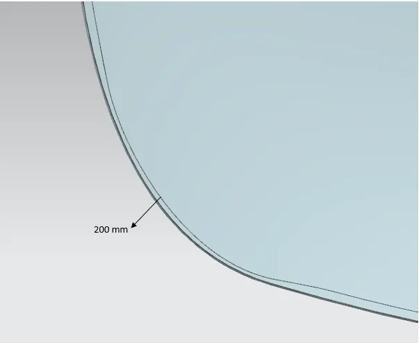
Relief is provided onto the part or component in order to remove any stresses developed in a particular area i.e sharp corners that take
place during the hemming process are carried out. Thus corners are rounded or chamfered.
We leaving 2 mm from sheet metal for the Roll hemming process.
Corner Relief Parameters:
Features Used in NX Cad:
Offset Surface:
The offset surface command is used to offset a surface or face. Selecting a surface to offset will generate an IntelliShape offset surface that is
defined by the originating surface. This IntelliShape will update if the originating surface is modified
Offset in the face:
Use the Offset Face command to offset one or more faces along the face normals. You can offset faces either by positive or negative distances,
provided the topology of the body does not change.
Trim sheet:
Use the Trimmed Sheet command to trim sheet bodies to intersecting faces and datums, and projected curves and edges.
Through curves:
through curves, the command used to create a body through multiple sections where the shape changes to pass through each section. Sections
are curves, points, solid edges, solid faces.
Law Extension:
Use the Law Extension command to extend an existing surface or sheet based on the laws for distance and the angle of the extension. Law
Extension creates flanges or extensions when a particular direction is important or when it is necessary to reference the existing face
Trim and extend:
This option lets you extend and trim one or more surfaces using a set of tool objects composed of edges or surfaces. 1 Two intersecting solid
bodies. 2 Selected body on the right is the object to trim (the target).
Face Blend
Face Blend is enhanced to provide a dedicated type for blending along intersection edges of bodies combined with a Boolean feature. Face Blend is
primarily used to blend between faces of separate bodies. It can also be used to blend between faces of a single body.
Edge blend
Edge blend command uses to round sharp edges between faces. The radius can be constant or variable.
Emboss
Emboss is mainly used on surfaces, you can use an intersecting solid as Michael shows, you can also use a curve or sketch profile. create your
sheet feature. select emboss, and select your face and sketch. Attached is an example of an embossed sheet.
Sketch:
Creates a sketch in the current application. Use the direct sketch tools to add curves, dimensions, constraints, etc.
Datum plane:
Creates a datum plane used to construct other features.
WAVE Geometry Linker:
Copies geometry from other parts in the assembly into the work part.
Extend sheet:
Extend a sheet body by distance or to the intersection with another body.
Mirror geometry:
Copies geometries and mirror them across a plane.
Sew:
sew command used to combine sheet bodies by sewing common edges together, or combines solid bodies by sewing common faces. The selected
sheet bodies must not have any gaps larger than the specified tolerance
Thicken:
Use the Thicken command to offset one or more connected faces or sheets into a solid body. Thickening occurs by offsetting the selected faces
along their face normals and then creating sidewalls. The Thicken command is similar to the Offset Face command.
The curve on a surface:
Creates a surface spline features directly on the face.
Extract body:
Use the Extract Body command to create an associative body by extracting faces from another body.
Hood Assembly Views
Front View:
Back View:
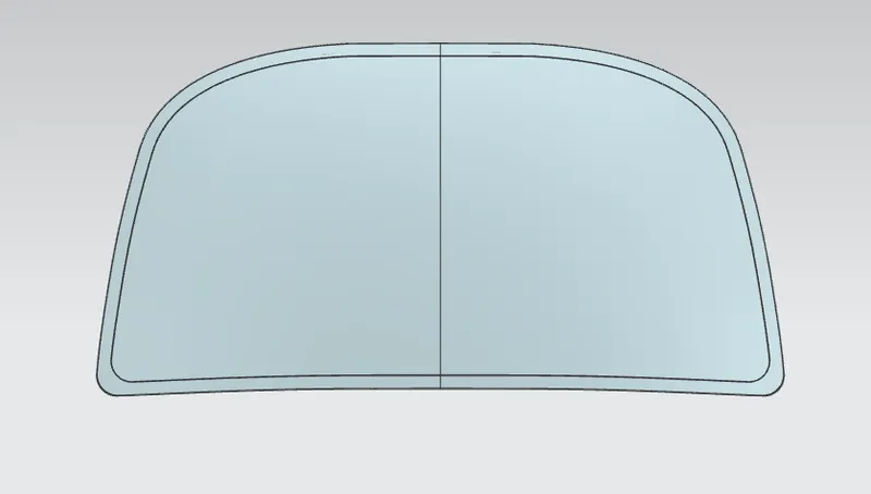
Top View:
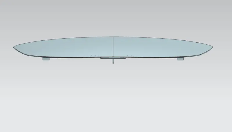
Bottom View:
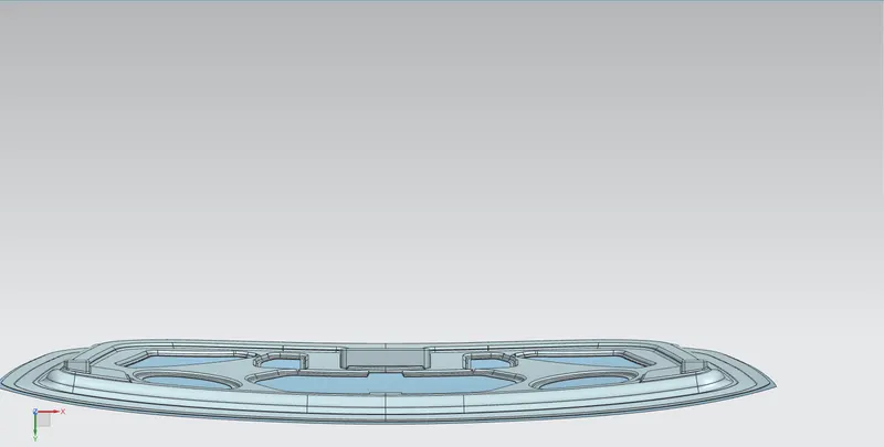
Side View:
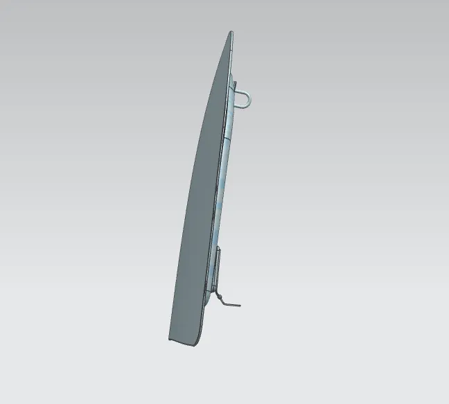
Isometric View:
Conclusion:-
The Hood design successfully completed with help of NX Cad Tools. Surface Tools are most commonly used to design hood, tools like Offset
Surface, Trim Sheet, Law Extension, Emboss, etc.