DESIGNING OF CAR HOOD/BONNET - NX CAD
OBJECTIVE:
Project is about to design a Hood or Bonnet BIW that satisfies the manufacturing requirements, functional requirements as per Euro NCAP standards.
INTRODUCTION:
Hood may be hinged at either front or rear edge in earlier models. It may be split into two sections one each side, each hinged along the centerline. A further variant combines the bonnet and wheel arches into one section and allows the entire front body work to tilt forward around a pivot near the front of the vehicle.
Hood is made aerodynamic in shape to reduce air effect and used to decorate the front portion of the car and to add a luxurious looks of cars. Hood generally used to cover car engines, radiators and many other components, therefore the hood must be designed in such a way that all the maintenance on the engine. In addition to that if it come across any accidents from the front portion most of the time the hood system gets damaged first and absorbs most of the impact energy resulting from the crash.
PURPOSE OF HOOD DESIGN:
- Safety of Passengers.
- Covers all Engine, radiator & other components.
- Reduce air effect due to its aerodynamic shape design
- Reduces Engine noise which helps for quieter drive.
- Provide access to the engine maintenance.
- It can give enough time to passengers to getout of the car before the fire blaze out of hood.
COMPONENTS OF HOOD:
- Hood Outer Panel
- Hood Inner Panel
- Latch & Stricker reinforcement
- Hinge reinforcements
- Stiffner Pad
DESIGN ASPECTS:
- Pedestrian safety:
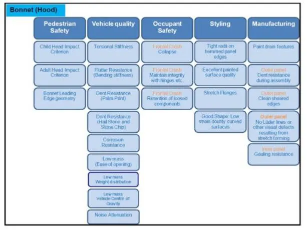
Pedestrian safety from front collision is also to be considered. The European New Car Assessment Program (Euro NCAP) is a European car safety performance assessment program which has developed test specification and rating systems for assessing pedestrian injuries during impacts with the front of vehicles such tests include a series of tests using impactors designed to mimic a collision at a speed of 40Kmph. They describe a situation in which pedestrian is situated laterally and a car first hits one of his legs. Tests are conducted on the leg, upper leg and most importantly head, as head trauma is most commonly responsible for casualties.
- Vehicle Quality-
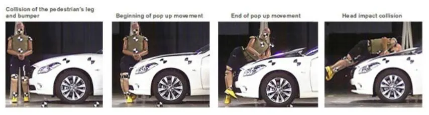
Torisonal stiffness, Flutter resistance, dent resistance (Palm print), dent resistance (Hail/stone chip), Corrosion resistance, low mass- ease of opening, low mass - Vehicle COG, Noise attenuation.
- Occupant Safety - Collapse - Front Impact, System Integrity - Impact, Retention - Impact.
- Styling - Tight Hem flanges, Painted surface quality, Stretch flanges, shape in low strained areas.
- Manufacturing - Paint drain features, Outer panel dent resistance, clean sheared edges, surface quality post forming, Galling resistance - Inner panel, Manufacturing occupant - Safety quality.
MATERIAL REQUIREMENTS:
Hoods are typically made out of the same material as the rest of the body work, this includes Steel and Aluminum. However, some market companies produce replacements for steel hoods with Fiber glass or carbon fiber to make vehicle lighter.
MANUFACTURING REQUIREMENTS:
- Deep Drawing process is used for manufacturing of the Inner Panel.
- No sharp Corners
- Material requirements - Steel, Aluminium, Fibers.
- No negative draft.
- Provide appropriate corner relief on the area of curvature.
- Outer Panel Thickness = 0.75mm
- Inner Panel Thickness = 0.75mm
- Reinforcement Thickness = 1.5mm
SHEETMETAL OPERATIONS:
- Blanking and Piercing
- Deep Drawing
- Embossing
- Hemming
- Blanking & Piercing - In Blanking, Piercing & Shearing processes a punch and die are used to modify webs. The tooling and processes are between the two are same, only the terminology is different. In blanking the punched out piece is used and called Blank where as in piercing the punched out piece is scrap. The Process for parts manufactured simultaneously with both techniques is often termed pierce and blank, an alternative of piercing is punching.
Purpose -
- Reduce the body of weight.
- Improve the strength of the body.
- Distribute Impact force.
- Improve Mileage of car.
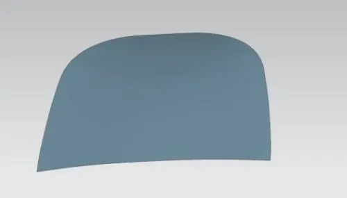
Fig. - Blanking
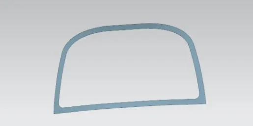
Fig. - Piercing
2. Deep Drawing -
- Deep drawing of sheet metal is used to form object with depth. It is a plastic deformation in which a flat sheetmetal or plate is formed into a recessed three dimensionpart with a depth several times the thickness of the metal.
- The process of deep draing begins with a flat sheetmetal held on the upper surface of the die. It is used in manufacturing inner panel.
- Material used is Aluminium as it can absorb twice the crash energy of Mildsteel. Lighter Dent free and make body panels thicker while still lowering weight.
Purpose -
- Operation in which thickness of the shell wall is reduced and its surface smooth. When material gets compress between punch and die, which reduce the thickness and increase the height of the cup.
3. Embossing -
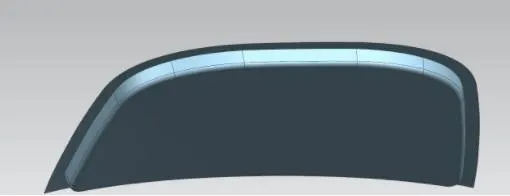
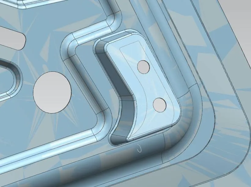
- Sheet metal embossing is a stamping process for producing raised or sunken designs or relief in sheetmetal. This Process can be made by means of matched male and female roller dies or by passing sheet or a strip of metal between rolls of the desired pattern.
- It is done by pressing a sheet of paper into female die, that has a design attached into it. This is usually done with a male counter part underneath the paper so that the two and design is transferred to the paper.
Purpose -
- Embossing enables you to highlight important elements of your printed products, such as letters(Company name) and designs (your corporate logo), to make sure they standout. Embossing can also be combined with foil stamping to help create the effect of a 3D image on printed paper that really shines.
4. Hemming -
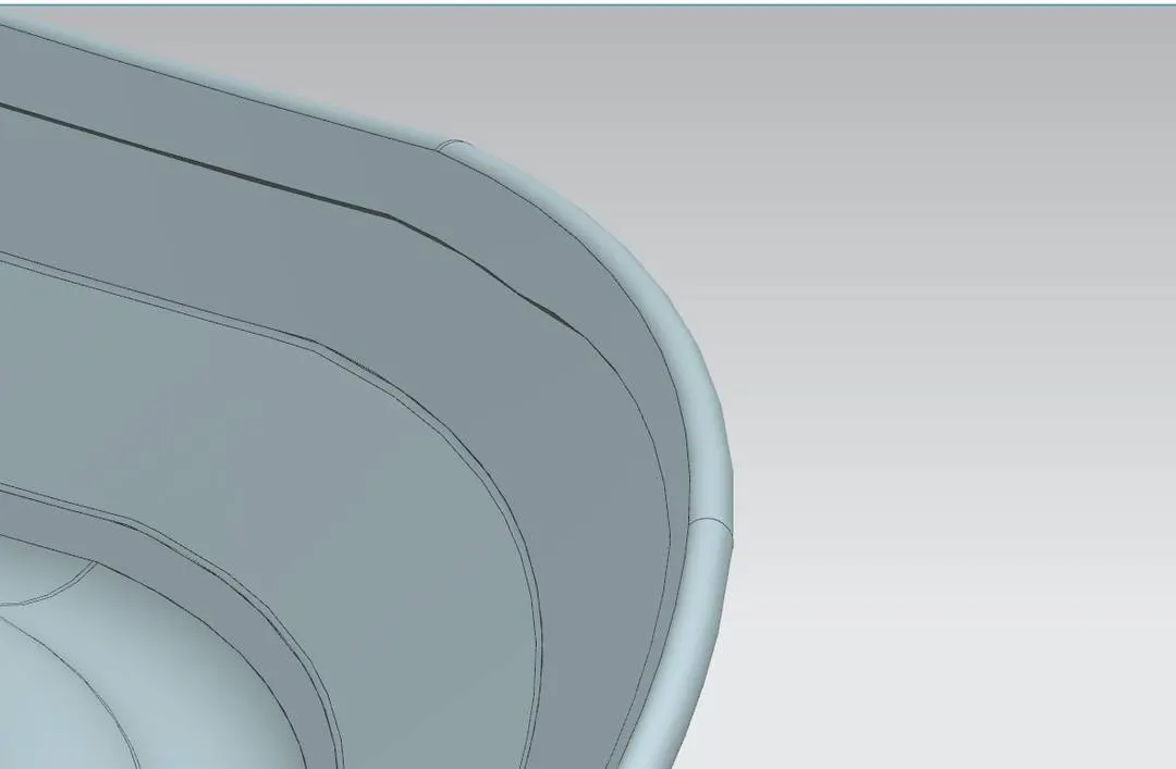
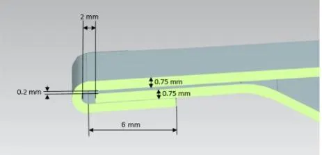
- Hemming is a Sheet metal forming process in which sheets are joined by bending it to 180 degree. Automotive body panels and automative parts such as deck-lids, trunk-lids, doors, hoods and tailgates are formed by the hemming process, in this process usually a sheet is bent with the help of inner and outer sheet.
- Hemming is a forming operation in which the edges of the sheet are folded over another part in achieve a tight fit.
Purpose - To fasten two sheet metal parts by folding the edge of sheet back on itself.
Types of Hemmings:
- Open Hemming
- Teared drop Hemming
- Closed Hemming
- Rolled Hemming
WAY OF APPROACH:
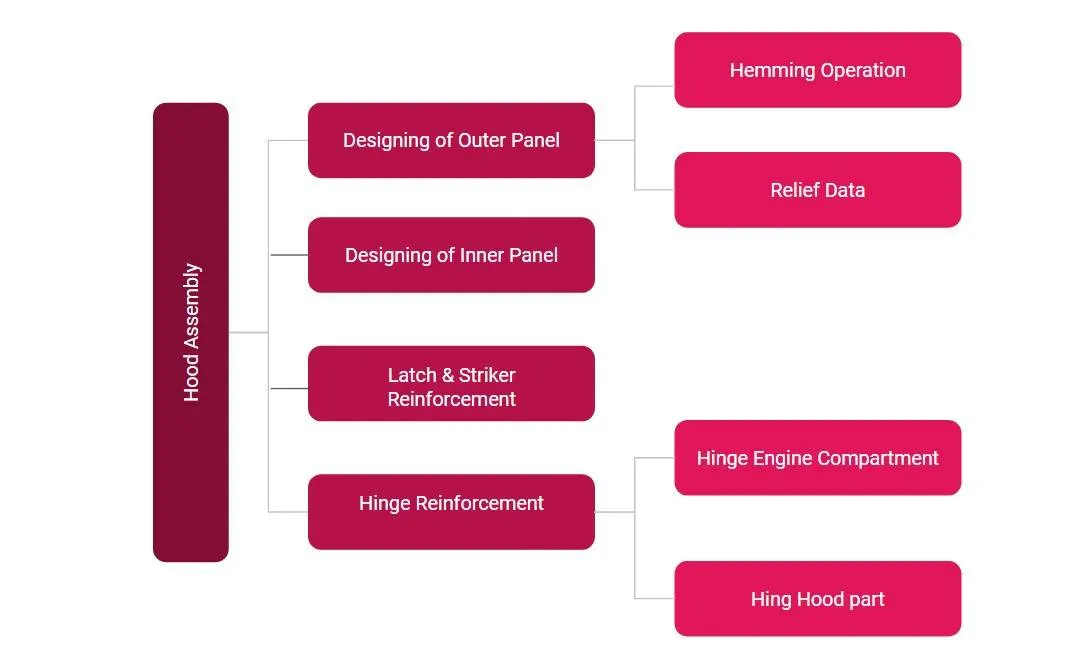
- Top - down Approach - Top down assembly design, one or more features of a part are defined by something in an assembly such as layout sketch or the geometry of another part. The design intent comes from the top (the assembly) and moves down (into parts), hence the phrase "Top-down".
DESIGNING OF COMPONENTS:
1. Designing of Inner Panel:
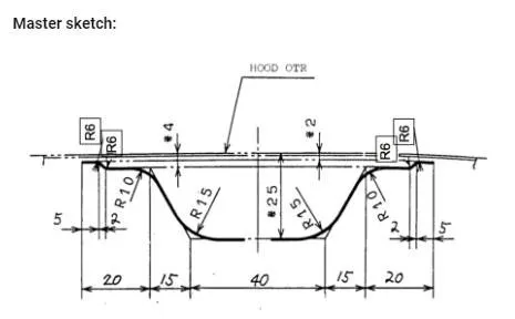
- Master Section: The master section is created based on the requirements received from the marketability team and the manufacturing requirements.
- Extract the Body from the given dump solidy body and start creating Inner panel using that extracted one.
- Create a part file in Assembly named after "Inner Panel". Trim the half portion of it as we are going to mirror it at the end.
- Create a Offset surfaces as per Sketch from Linked body.
- Use Offset curve on face to create curves on faces using edges and trim off the unwanted portion.
- Use Through Curves command by selecting appropriate surfaces which usually creates a body through multiple sections where the shape changes through each section.
- Create one more surface using Offset Surface and connect it with previous surface using Law extension. Trim off the over extened portion using Trim & extend.
- Blend the faces of the sheets using Face Blend by giving appropriate dimensions.
- Now create a Sketch by selecting a plane parallel to the panel surface and project the curves on the panel using Projected curve.
- Create a Emboss to modify the body with faces made by projecting a section along a vector by selecting embossed face as end face and projected curve as curve. Use Edge blend to blend them.
- Create few more embosses as per requirement by projecting drawn sketches on panel.
- Use Trim sheet to create voids or holes on sheet as per requirement.
- Hinge Emboss - Use wave geometry linker to extract the hinge face and use it as reference to create sketch for its positioning.
- Latch Emboss - This emboss is created once the trajectory of Hood Opening and Closing finalized.
- Thicken the Part at the end to make it solid body.
2. Mastic Data Design :
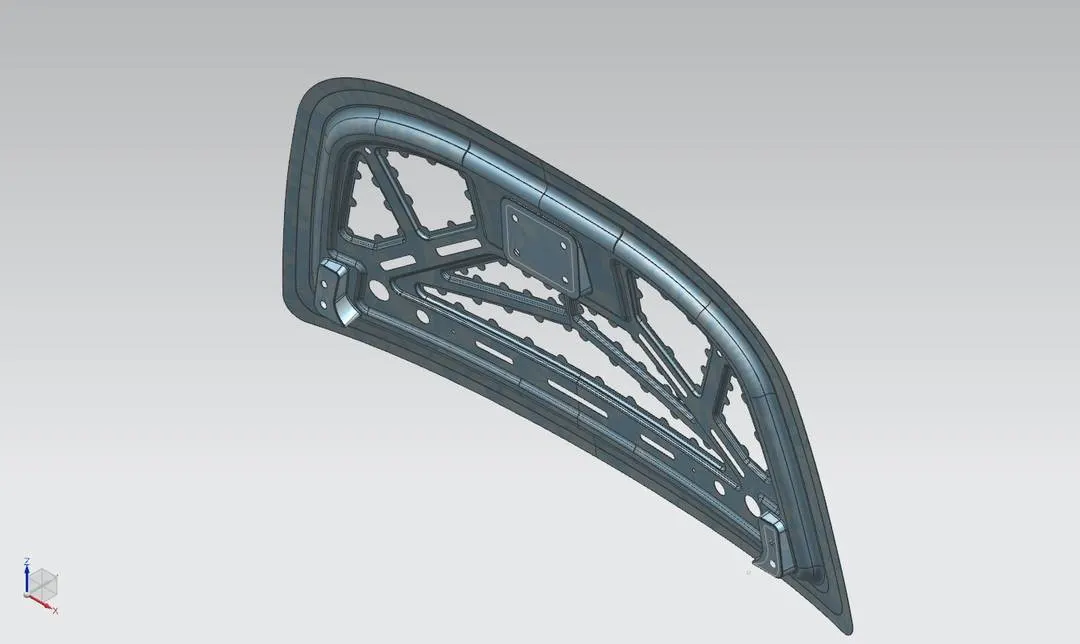
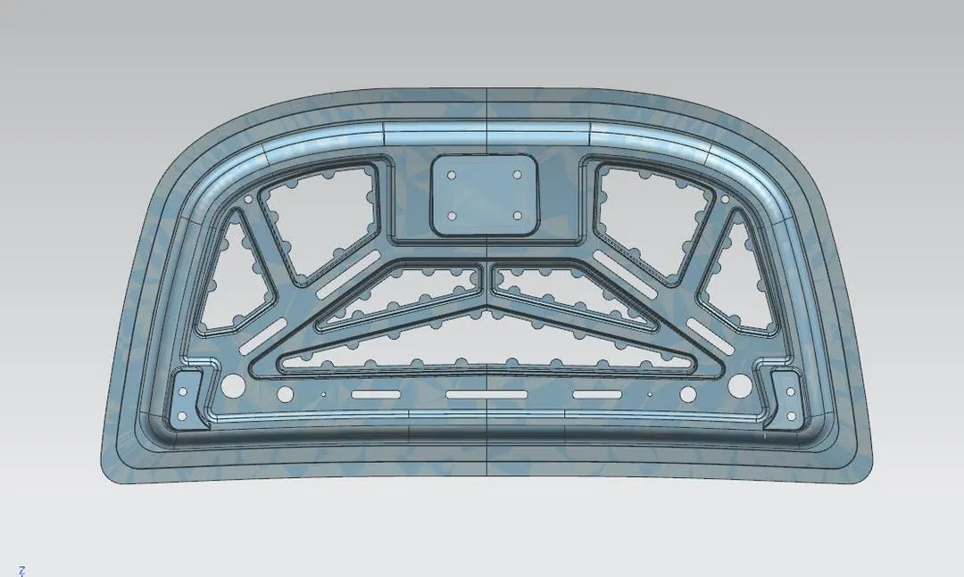
- The main purpose of the Outer Panel is for aesthetic looks. Thus we cannot use bolts or welding, this has to be done with the help of Hemming and Mastic sealants.
- Mastic sealants are elastic compound that behaves like the rubber. It is placed between the outer and inner panels. Initially it is in paste form but after the hot furnace bath, it will gets hardned thus joining the outer panel and inner panel. Mastic sealants has the tendency to increase the strength of the panel and has the influence of 80mm diameter.
- Usually in designing these are created in Inner Pannel using sketches and projecting them on panel. Later trimming of the sheet and blending it.
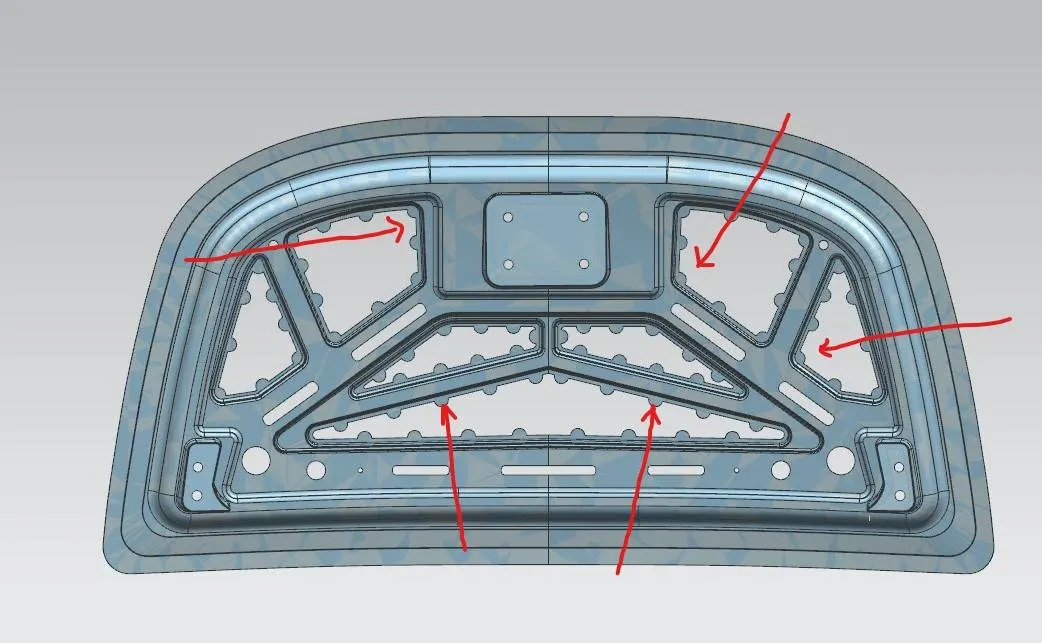
3. Latch & Hinge Reinforcement:
- To further more reduce the impact to the occupants inside the car, additional latch and hinge reinforcements are provided to the hood. When latch and striker are place, there is a drop in strength at that position thus reinforcements are provided to compensate that loss. Alos stiffner pads are placed to reduce NVH (Noise Vibration Hardness). Hinge and latch reinforcements thickness are kept at 1.2 mm but it may vary.
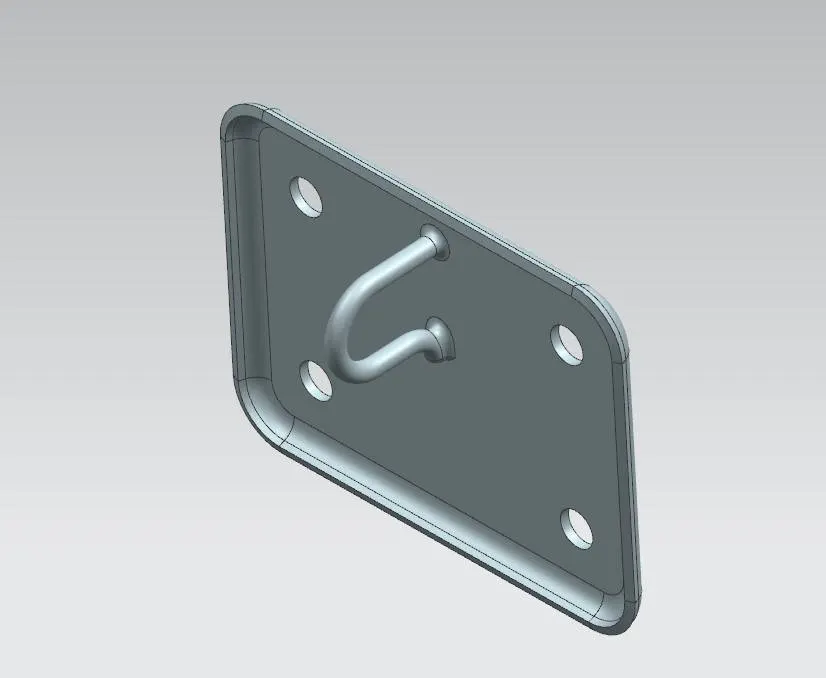
Fig. - Latch & Striker Reniforcement
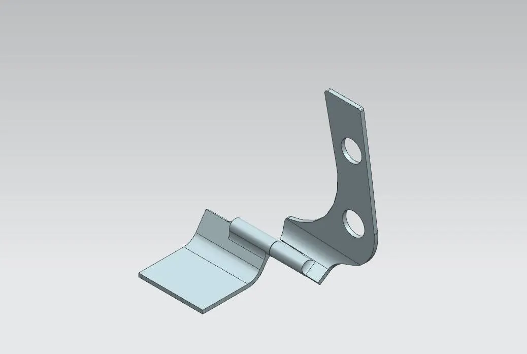
Fig. - Hinge Reniforcement
4. Hinge & Striker Positioning:
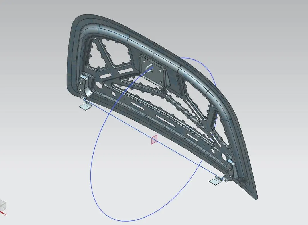
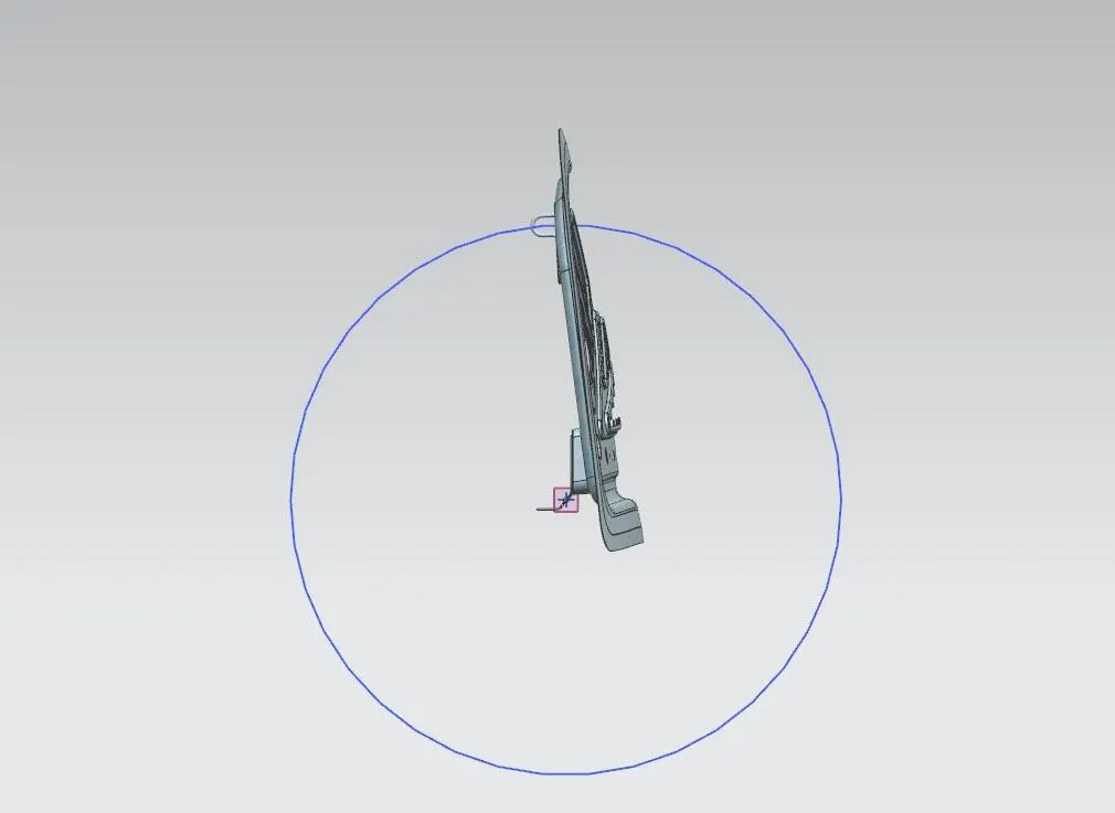
- For proper opening and closing of hood, the striker should be perpendicular to the trajectory of the hood. For this, the hinge is assembled at its positon.
- Once it is placed, the hinge axis is drawn by connecting sketch points created on hinge edges.
- Create a Datum Plane using midpoint of hinge axis.
- Now sketch a circle to in such a way that helps in positioning latch.
- Now Postion the latch using above drawn circle which has to be perpendicular to the hood trajectory.
- Once positioned create a Emboss on Inner Panel by extracting the face of the latch.
5. Designing of Outer Panel:
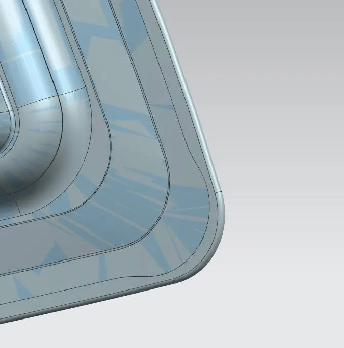
- Hemming:
- Use Offset curve on face to create curves along the faces by selecting above offset surface.
- Extend the sheet by selecting the above offseted curve.
- Create one more surface at an offset of calculating thickness and gap between flanges on opposite direction to above surface.
- Offset the above created law extension as per requirement using offset face.
- Now Trim the extra surfaces which are not required.
- Use Face blend and select the top, rear and middle face to create Hemming.
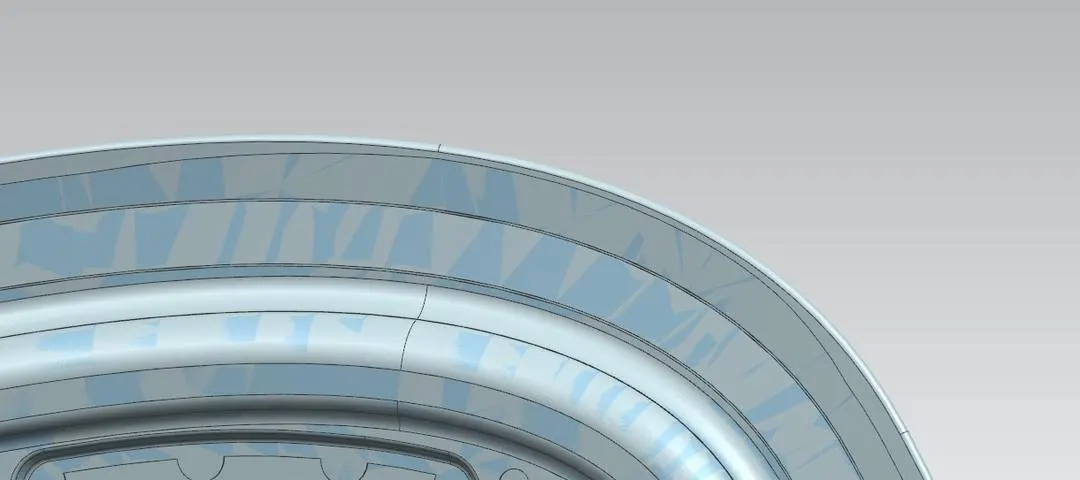
b. Relief Data:
- Relief is provided onto the part or component in order to remove any stresses developed in a particular area i.e. sharp corners that take place during hemming process are carried out. Thus corners are rounded or chamfered.
- Create a Sketch and project it on Panel using Project curve. Trim the extra portion using Trim sheet by selecting projected sketch as boundary.
COMMANDS USED:
- Extract Geometry - Creates associative copies of bodies, faces, curves, points and datums and associative mirrored copies of bodies, within the same part.
- Trim Sheet - Trims off a portion of a sheet body.
- Offset Surface - Creates a body by offsetting a set of faces.
- Offset Curve in Face - Offsets curves along the faces on which they lie.
- Through Curves - Creates a body through multiple sections where the shape changes to pass through each section.
- Law Extension - Creates a law-controlled extension from a base sheet, dynamically or based on laws for distance and angle.
- Face Blend - Adds tangent blend faces between selected sets of faces. The blend shape can be circular, conic or law controlled.
- Trim and Extend - Trim or extends a set of edges or faces to the intersection with another set of edges or faces.
- Edge Blend - Rounds sharp edges between faces. The radius can be constant or variable.
- Project Curve - Projects curves, edges or points onto faces or planes.
- Emboss - Modifies a body with faces made by projecting a section along a vector with options for end cap loctaion and shape.
- Mirror Geometry - Copies geometries and mirrors them across a plane.
- Extend Sheet - Extends a sheet body by distance or to the intersection with another body.
- Sew - Combines sheet bodies by sewing common edges together or combines solidies by sewing common faces.
- Thicken - Creates a solid body by adding thickness to a set of faces.
- Wave Geometry Linker - Copies geometry from other parts in the assembly into the work part.
DRAFT ANALYSIS:
Draft Analysis is carried out to see that the panel can be drawn or not. It also helps to find the negative draft present in the component which can cause difficulty in manufacturability.
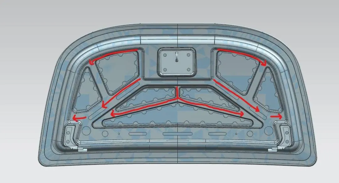
FORCE DISTRIBUTION:
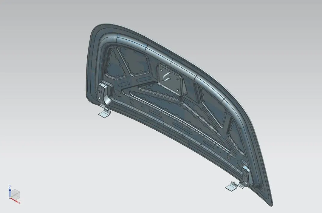
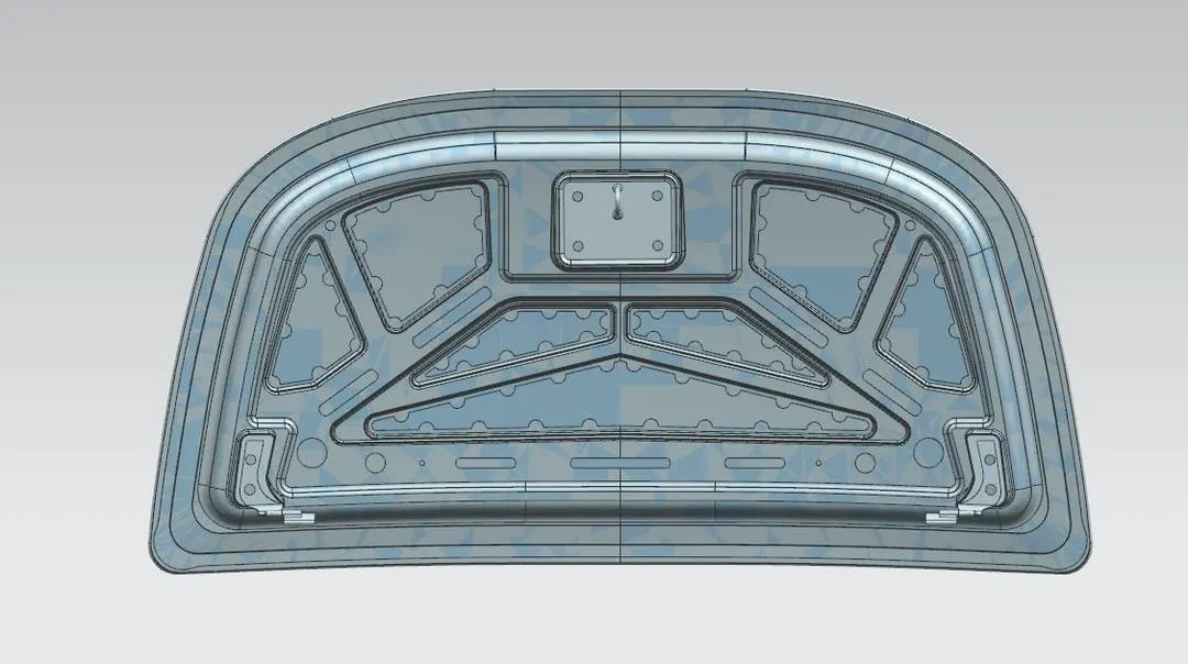
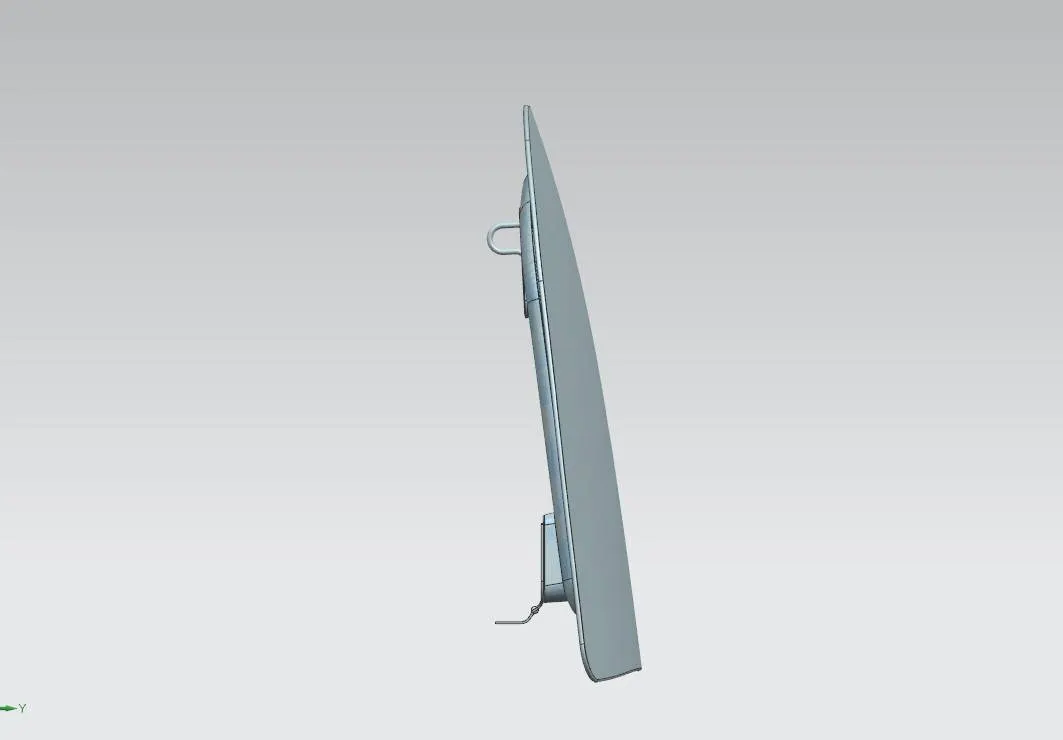
HOOD ASSEMBLY:
CONCLUSION:
Thus a Hood is designed in a top- down approach where the intent comes from the top (the assembly) and moves down (into the parts), which satifies the industry's manufacturing requirements, functional as well as Safety standards (Euro NCAP) in NX CAD tool.