Designing Of Robotic Arm Components, Assembly & Rendering - Solidworks
Designing of Robotic Arm Components, Assembly & Modelling – Solidworks
OBJECTIVE:
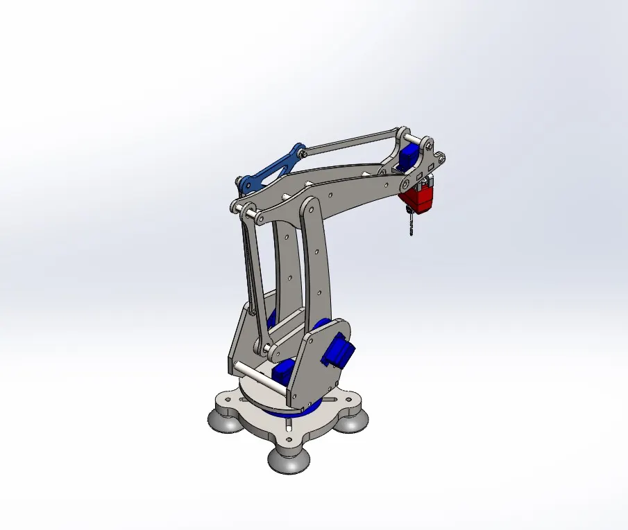
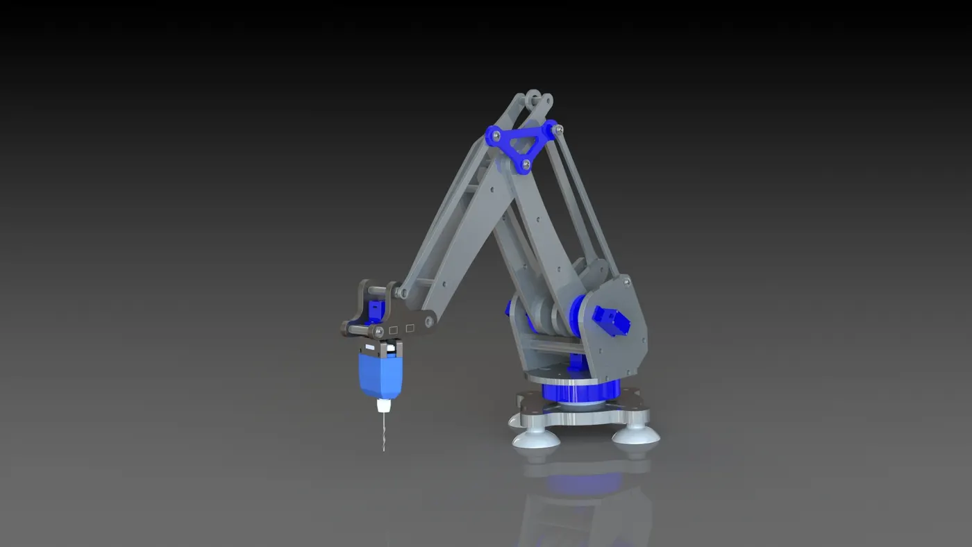
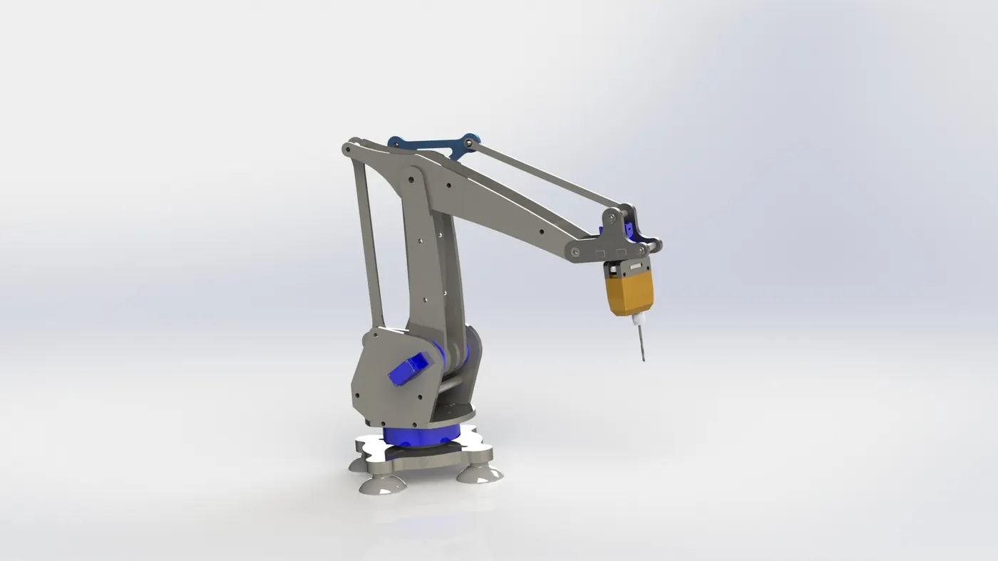
To Design Robotic arm with Drill machine as a end effector in Solidworks and Modelling in PV360 to give realistic look.
INTRODUCTION:
- A Robot is a machine – especially one programmable by a computer – capable of carrying out a complex series of actions automatically.
- Essential Characteristics – Sensing, Movement, Energy & Intelligence.
- The first Robotic arm, which Devol and Engleberger called Ultimate#001, was made in 1959. In 1961, Devol was awarded a patent for his Invention and Engleberger established the world's first robot company, Unimation.
Types of Robot:
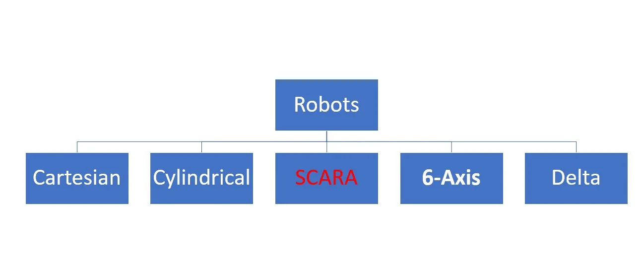
Plan of Action/Way of Approach:
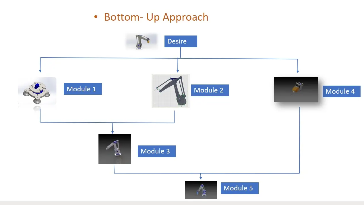
Bottom- Up Approach:
Bottom-up Design is the traditional method. You first design and model parts, then insert them into an assembly and use mates to Position Parts. To change the parts, you must edit them individually. These changes are then seen in the asseembly.
Module 1:
It's a Base Assembly consists of 3 main sections.
- Designing Part 9 to Part 15.
- Assemble the base.
- Attach the servomotor and make it to work.
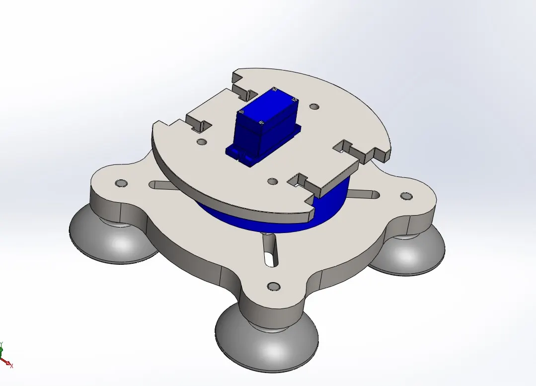
a. Components of Module 1:
- Part 9:
Feature Tools - Extruded Boss/Base, Extruded Cut, Fillet.
Sketch Tools - Sketch Geometry like - line, rectangle, arc, Circle.
Render Image - PV 360
Extruded Boss/Base - Extrudes a sketch or selcted sketch contours in one or two directions to create a solid feature.
Extruded Cut - Cuts a solid model by extruding a sketched profile in one or two direction.
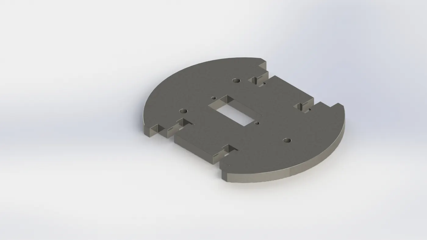
PROCEDURE:
- Top Plane -Draw a horizontal, vertical line and a rectangle from origin. Draw a spider web like structure using lines and arcs. Add 3 circles in between rectangle and outer edge, Extrude it.
- Draw a sketch on Top face of above Extrude by using 2 rectangles, draw in such a way that they are perpendicular to eachother(vertical and horizontal rectangle intersecting length & breadth of respective rectangles).,do Cut extrude.
- Apply fillet and give proper Appearance.
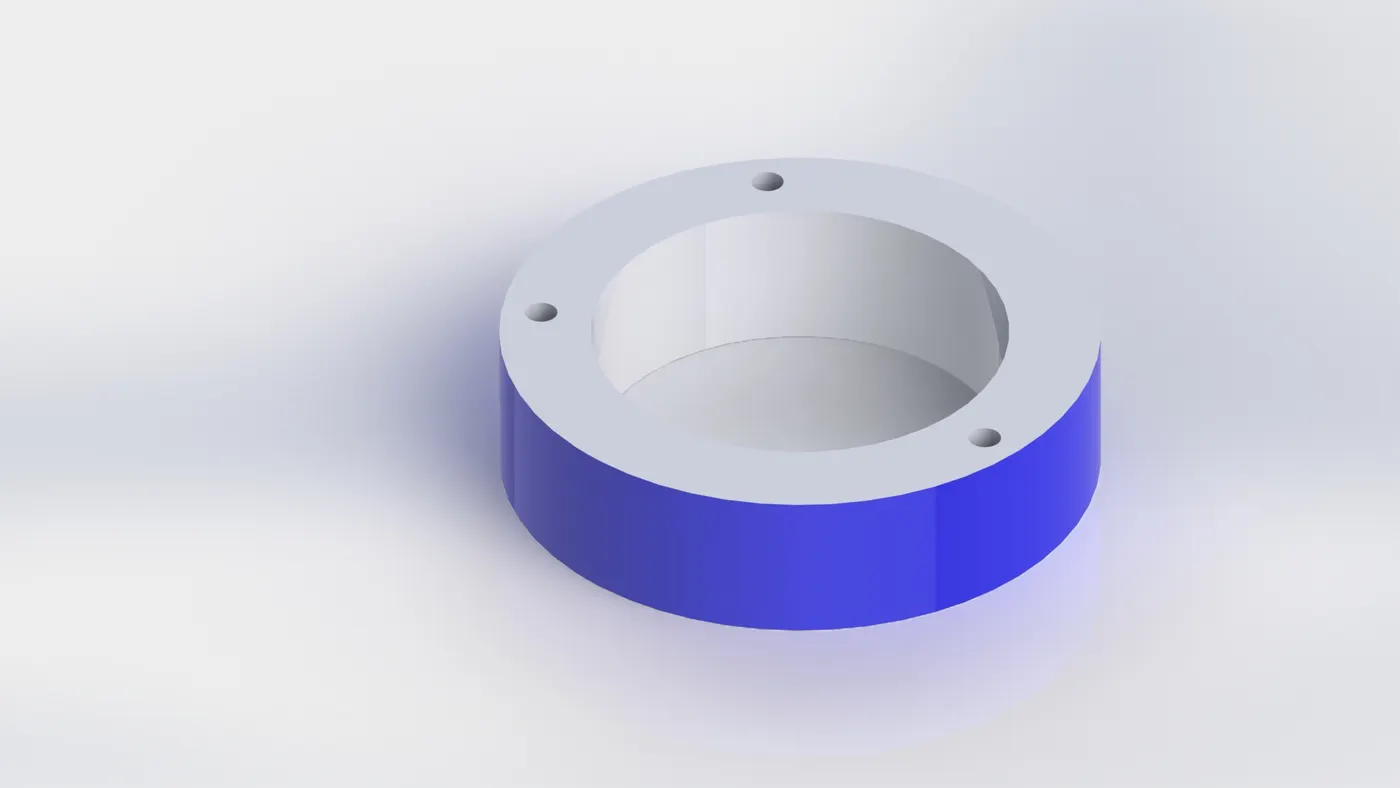
2. Part 10:
Feature Tools - Extruded Boss/Base.
Sketch Tools - Sketch Geometry like - Circle.
Render Image - PV 360
PROCEDURE:
- Top Plane -Draw two circles with an offset at Origin. Sketch 3 circles for hole creation at certain angles between pervious drawn offset circles.,Extrude it.
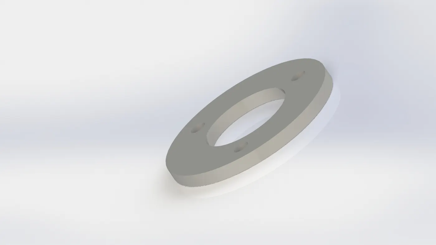
3. Part 11:
Feature Tools - Extruded Boss/Base.
Sketch Tools - Sketch Geometry like - Circle.
Render Image - PV 360
PROCEDURE:
- Top Plane - Similarly as Part 10, Draw two circles with an offset at Origin. Sketch 3 circles for hole creation at certain angles between pervious drawn offset circles.,Extrude it.
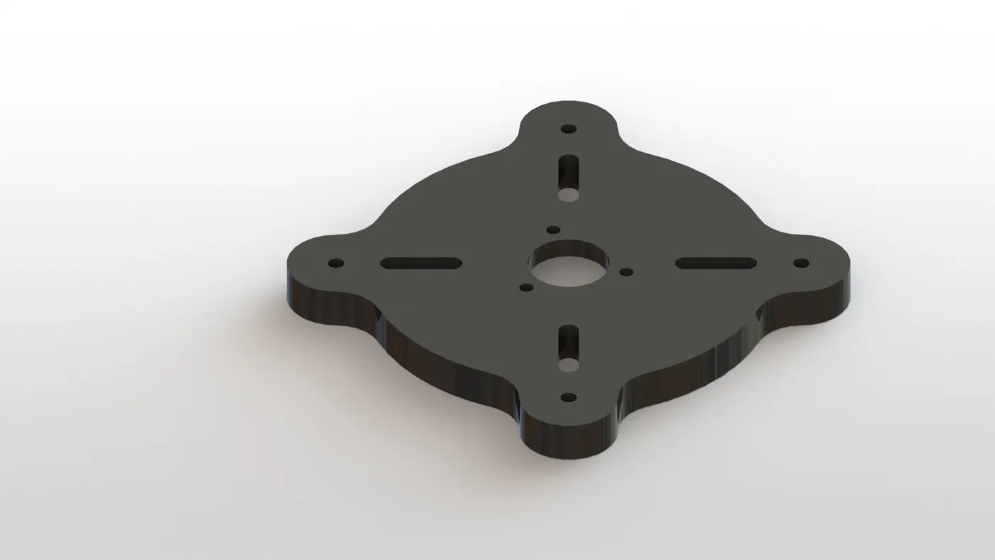
4. Part 12:
Feature Tools - Extruded Boss/Base, Extruded cut.
Sketch Tools - Sketch Geometry like - Circle, line & slot.
Render Image - PV 360
PROCEDURE:
- Top Plane - Draw a sketch using circles, slots and lines and extrude it to create base of it.
- Draw a sketch on face of above extrude using circle at center to create holes, do cut extrude.
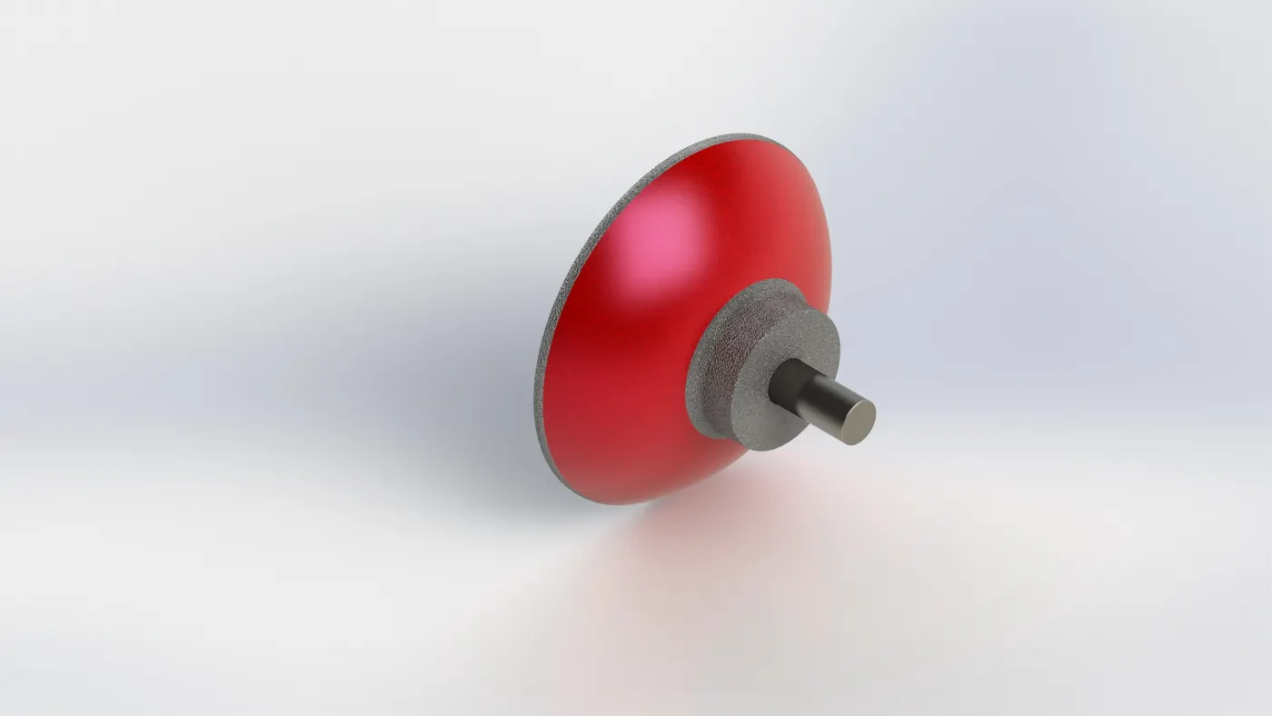
5. Part 13:
Feature Tools - Revolved Boss/Base, Fillet.
Sketch Tools - Sketch Geometry like - Circle, line & 3 point arc.
Render Image - PV 360
Revolved Boss/Base - Revolves a sketch or selcted sketch contours around an axis to create a solid feature.
PROCEDURE:
- Front Plane - Draw a horizontal and vertical construction line from origin. Sketch two arcs at an offest of 0.5 mm connecting previously drawn construction lines. Draw two rectangles as per dimensions and trim the inner edges and revolve it about horizontal line.
- Draw one more sketch on Front Plane using lines at center and revolve it about Horizonatl line to obtain a connecting pin.
- Apply Fillet and give proper Appearance.
6. Part 14:
Feature Tools - Revolved Boss/Base, Extruded Cut.
Sketch Tools - Sketch Geometry like - Circle, line.
Render Image - PV 360
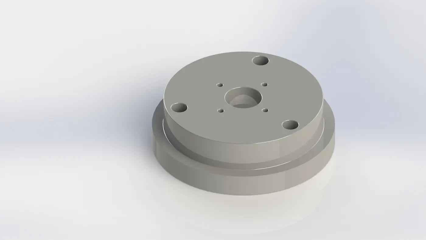
PROCEDURE:
- Front Plane - Draw a horizontal and vertical from origin and revolve it about Vertical axis.
- Draw a few circles and do cut extrude on bottom faces of above revolve.
- Apply Fillet and give appearance.
7. Part 15:
Feature Tools - Extruded Boss/Base.
Sketch Tools - Sketch Geometry like - Circle.
Render Image - PV 360
PROCEDURE:
- Top Plane - Similarly as Part 10, Draw two circles with an offset at Origin. Sketch 3 circles for hole creation at certain angles between pervious drawn offset circles.,Extrude it.
b. Assembly of Module 1:
In this portion all designed individual components/parts are assembled together for Module 1.
Steps to be followed for Assembling -
- All Designed Parts to be inserted one by one as per requirement.
- Apply mate condition with respective parts for giving exact location in Assembly.
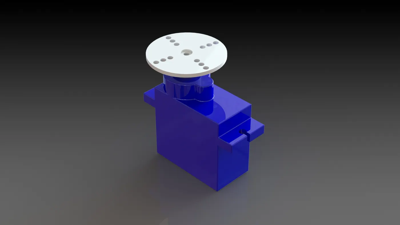
c. Attaching Servomotor -
- Designing Parts of Servomotor.
- Assembly of Servomotor.
- Attaching & Make it work.
Components -
- Middle Cover
- Bottom Cover
- Top Cover
- Gear
- Connecting rod
- Fan
Designing of Parts:
- Middle Cover:-
Feature Tools - Extruded Boss/Base, Extruded cut, Shell & Fillet.
Sketch Tools - Sketch Geometry like - Circle,rectangle, line & arc.
Render Image - PV 360
Shell - Removes a material from solid body to craete a thin walled feature.
Procedure :
- Top Plane - Draw a rectangle at origin and circles at corners to make a hole; extrude it.
- Apply Shell to the top face of the above extrdue.
- Use Sketch1 and selct circles as contours and do thin extrude.
- Select Lower face and draw 3 circles at a distance of appropriate dimension and do cut extrude of 2 circles.
- Do a thin extrude using remaining one circle in above sketch.
- Draw a sketch on lower face of cover using two inclined lines and a horizontal line connecting them., do thin extrude.
- Draw two rectangles on side faces and do extrude.
- Apply fillet and give proper Appearance.
Similarly Design Top and Bottom covers using above procedure with proper dimensions.
2. Servo Fan -
Feature Tools - Extruded Boss/Base, Extruded cut, Chamfer, Circular Driven Pattern & Mirror.
Sketch Tools - Sketch Geometry like - Circle,slot, line & arc, Linear sketch pattern.
Render Image - PV 360
Circular Driven Pattern - Patterns features, faces & bodies in circular direction.
Procedure :
- Top Plane - Draw a slot at origin make it construction. Sketch few lines and circles connecting them in the shape of a fan. Draw a circle at the end of slot and do linear pattern and mirror., extrude it.
- Draw two circles t an offset and extrude by selcting bottom face.
- For Teeth -Select the above extrude and sketch triangle using lines and do cut extrude.
- Draw one more circle at the center of above extrude and do cut extrude.
- Now do circular pattern of teeth and apply chamfer.
Assembly of Servomotor -
- Assemble all Designed Parts to be inserted one by one as per requirement.
- Insert a spur gear from Library for providing motion to Servo Fan.
- Insert Servo fan and apply appropriate mates which gear to desired motion, lock it.
Attaching Servomotor & make it work -
- Insert Servomotor in assembly and apply proper mates.
- Insert Ball bearing from Library and give proper mates, which helps to obtain desired motion.
B. MODULE 2:
Arm Layout Design and Drawing.
- Drawing the layout.
- Designing Part 1 to Part 8
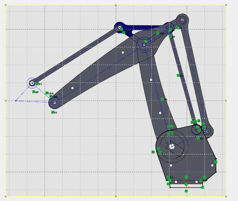
- Drawing Layout -
Its a Top down approach where one or more features of a part are defibed by something in an assembly such as layout sketch or the geometry of another Part. The Design intent comes from the top ( the assembly ) and moves down (into parts), hence the Phrase "top-down".
- Create a layout in Assembly file.
- Draw a complete Assembly( lower Arm & upper Arm) using lines, circles with proper dimensions.
- Check the movement of lines now and then so that it won't become a fixed one.
- Once Layout created, design parts by creating new part file by converting sketch entities.
b. Designing of Parts/Components -
- Part 1 :
Feature Tools - Extruded Boss/Base, Extruded cut, Hole wizard, Convert Entities & Fillet.
Sketch Tools - Sketch Geometry like - Circle, rectangle, Sketch Point.
Render Image - PV 360
Hole Wizard - It allows to quickly create holes within a part or assembly without the need of drawing or using multiple features.
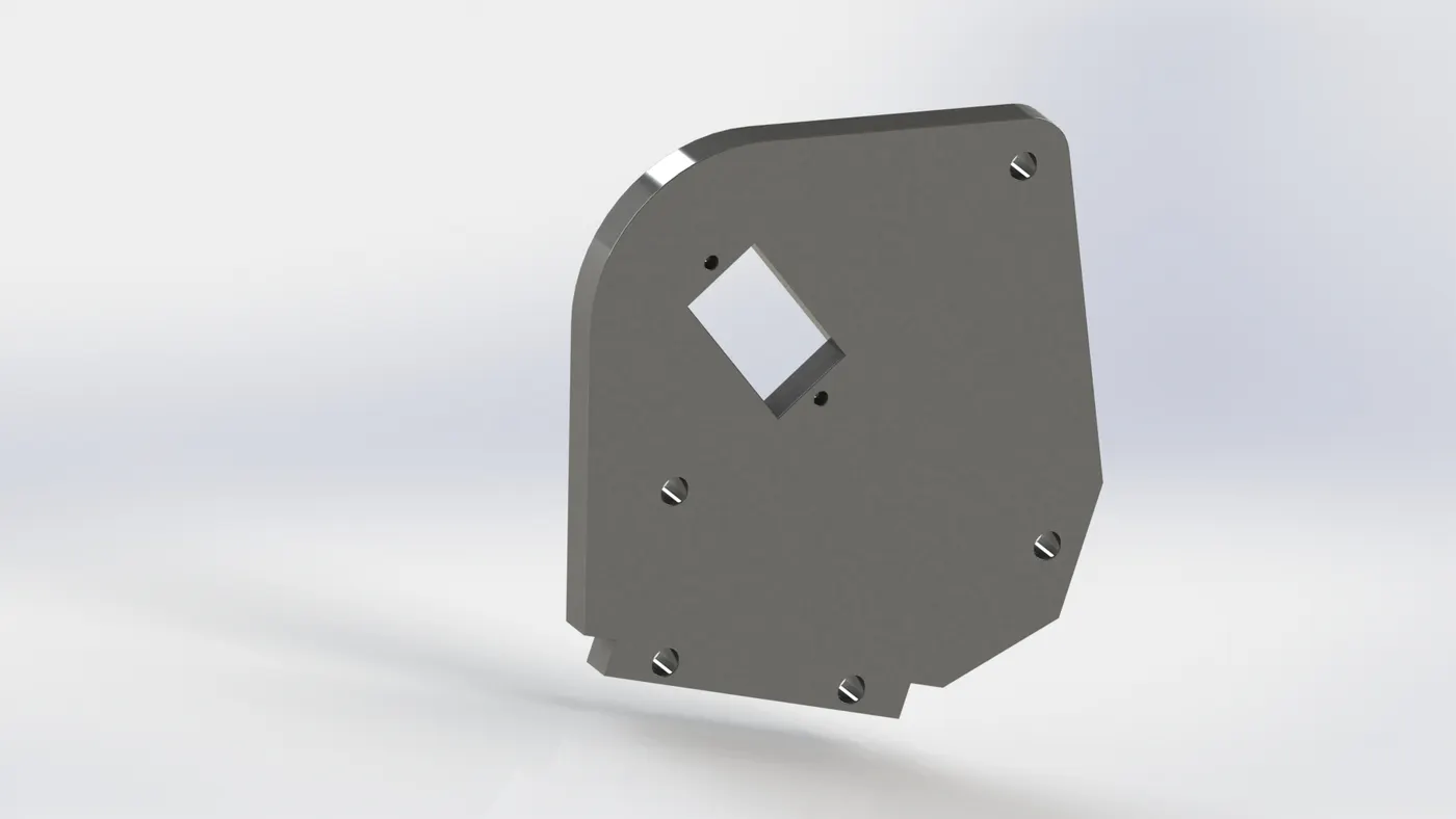
Procedure :
- Insert a Part File in Assembly.
- Open the Part file and sketch on Front Plane, convert the appropiate Sketch entities., Close it.
- Open Part file seperately, save it and edit the sketch.
- Front Plane -Draw a rectangle at an angle of 35 degree and a circle., extrdue it by selecting required contours.
- Draw a sketch on one of the face using sketch point to create holes using hole wizard.
- Draw one more sketch on face of above extrude using rectangle., do cut extrude.
- Apply Fillet and proper appearance to it.
2. Part 2 :
Feature Tools - Extruded Boss/Base, Hole wizard, Convert Entities & Fillet.
Sketch Tools - Sketch Geometry like - 3 point arc, Circle, Sketch Point.
Render Image - PV 360
Convert Entities - Converts selcted model edges or sketch entities into sketch segments.
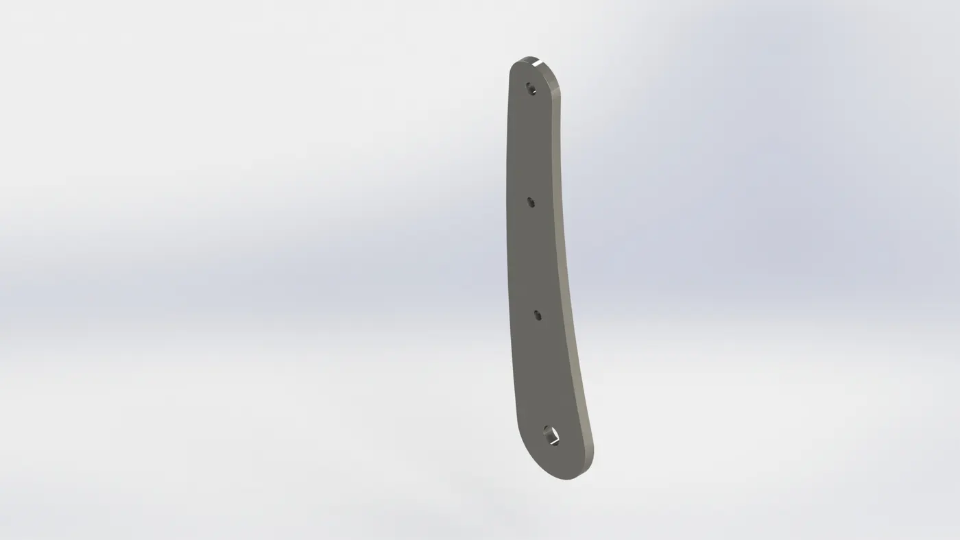
Procedure :
- Insert a Part File in Assembly.
- Open the Part file and sketch on Front Plane, convert the appropiate Sketch entities., Close it.
- Open Part file seperately, save it and edit the sketch.
- Front Plane - Draw 3 arcs at an offest and convert middle arc into construction. Sketch three circles at upper, lower and connecting portion. Draw 2 arcs at upper and lower portion to connect above drawn arcs, extrude it.
- Draw few sketch points at required portion to create holes using Hole Wizard.
- Apply fillet and proper appearance to it.
3. Part 3 :
Feature Tools - Extruded Boss/Base, Convert Entities & Fillet.
Sketch Tools - Sketch Geometry like - 3 point arc, Circle, slot.
Render Image - PV 360
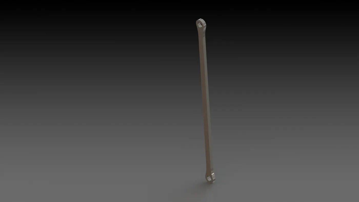
Procedure :
- Insert a Part File in Assembly.
- Open the Part file and sketch on Front Plane, convert the appropiate Sketch entities., Close it.
- Open Part file seperately, save it and edit the sketch.
- Front Plane - Draw a slot using convert entiies as reference (make it construction) and a circle at upper and lower portion. Sketch arcs to convert arcs of slot to circles., Extrrude it.
- Apply Fillet and give appearance to it.
4. Part 4 :
Feature Tools - Extruded Boss/Base, Convert Entities & Fillet.
Sketch Tools - Sketch Geometry like - 3 point arc, Circle, slot.
Render Image - PV 360
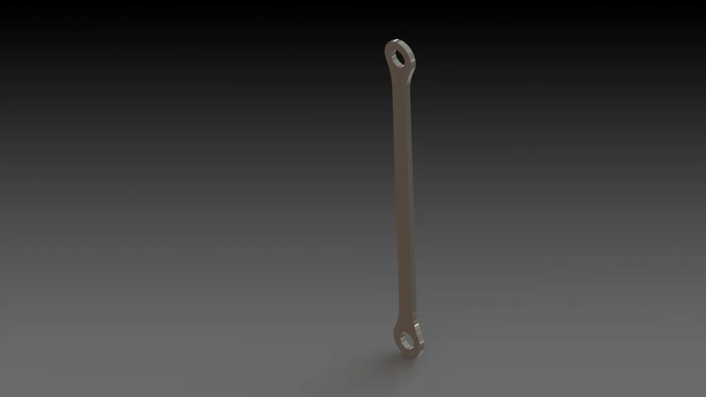
Procedure :
- Insert a Part File in Assembly.
- Open the Part file and sketch on Front Plane, convert the appropiate Sketch entities., Close it.
- Open Part file seperately, save it and edit the sketch.
- Front Plane - Draw a slot using convert entiies as reference (make it construction) and a circle at upper and lower portion. Sketch arcs to convert arcs of slot to circles., Extrrude it.
- Apply Fillet and give appearance to it.
5. Part 5 :
Feature Tools - Extruded Boss/Base, Hole wizard, Convert Entities & Fillet.
Sketch Tools - Sketch Geometry like - 3 point arc, Circle, Sketch Point.
Render Image - PV 360
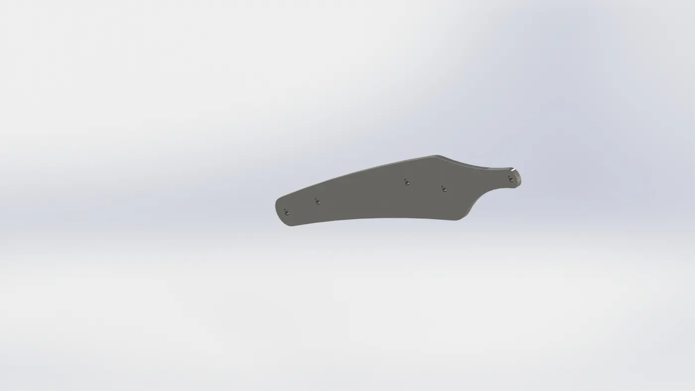
Procedure :
- Insert a Part File in Assembly.
- Open the Part file and sketch on Front Plane, convert the appropiate Sketch entities., Close it.
- Open Part file seperately, save it and edit the sketch.
- Front Plane - Draw 3 arcs at an offest and convert middle arc into construction. Sketch three circles at upper, lower and connecting portion. Draw one more circle at connecting portion at an offset make it construction. Sketch two arcs at upper and lower portion to connect above drawn arcs., Extrude it.
- Draw few sketch points on above extude face at proper portion to create holes using Hole wizard.
- Apply fillet and proper appearance.
6. Part 6 :
Feature Tools - Extruded Boss/Base, Convert Entities & Fillet.
Sketch Tools - Sketch Geometry like - 3 point arc, Circle, slot.
Render Image - PV 360
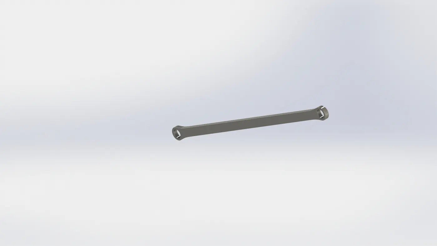
Procedure :
- Insert a Part File in Assembly.
- Open the Part file and sketch on Front Plane, convert the appropiate Sketch entities., Close it.
- Open Part file seperately, save it and edit the sketch.
- Front Plane - Draw a slot using convert entiies as reference (make it construction) and a circle at upper and lower portion. Sketch arcs to convert arcs of slot to circles., Extrrude it.
- Apply Fillet and give appearance to it.
7. Part 7 :
Feature Tools - Extruded Boss/Base, Convert Entities & Fillet.
Sketch Tools - Sketch Geometry like - Line, Circle.
Render Image - PV 360
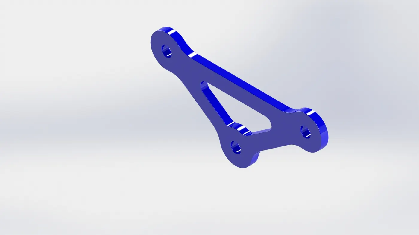
Procedure :
- Insert a Part File in Assembly.
- Open the Part file and sketch on Front Plane, convert the appropiate Sketch entities., Close it.
- Open Part file seperately, save it and edit the sketch.
- Front Plane - Draw 3 circles at the connecting edges of converted entities. Sketch three more circles at an offset and extude it.
- Draw 3 lines in a traingular shape without intersecting end points on above extrude face., Extrude it.
- Apply fillet and give appearance.
8. Part 8 :
Feature Tools - Extruded Boss/Base, Convert Entities & Fillet.
Sketch Tools - Sketch Geometry like - Line, Circle.
Render Image - PV 360
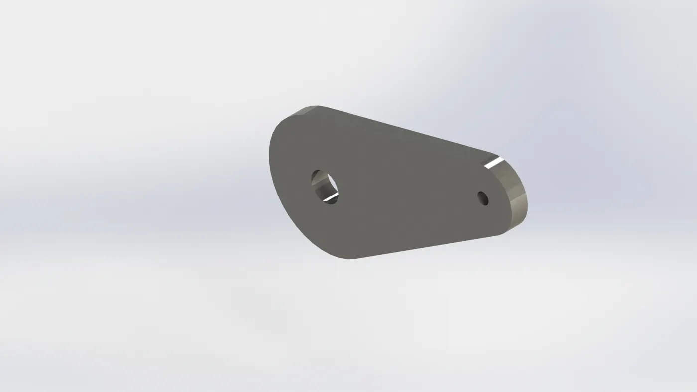
Procedure :
- Insert a Part File in Assembly.
- Open the Part file and sketch on Front Plane, convert the appropiate Sketch entities., Close it.
- Open Part file seperately, save it and edit the sketch.
- Front Plane - Draw a circle at end points of converted linnes. Sketch lines by connecting circles upper and lower end. Draw two more circles at same point at an offset. Extrude it.
C. MODULE 3:
Arm Assembly: Assembly which started in Module 1 and assemble the arm to base.
- Assemble the lower part of arm and fixing it.
- Assemble the Upper part of the arm and fixing it.
Steps to be followed for Assembling -
- All Designed Parts to be inserted one by one as per requirement.
- Apply mate condition with respective parts for giving exact location in Assembly.
- Insert 2 Servomotors at proper location and make it work.
- Insert Pins, Screws & nuts at appropriate parts.

D. MODULE 4: (End Effector)
In this module components of end effector designed and assembled together.
- Designing of Components/Parts.
- Assembling of Designed Parts.
- Designing of Components/Parts:
1. Part 1 :
Feature Tools - Extruded Boss/Base & Fillet.
Sketch Tools - Sketch Geometry like - Line, Circle, slot & arc.
Render Image - PV 360
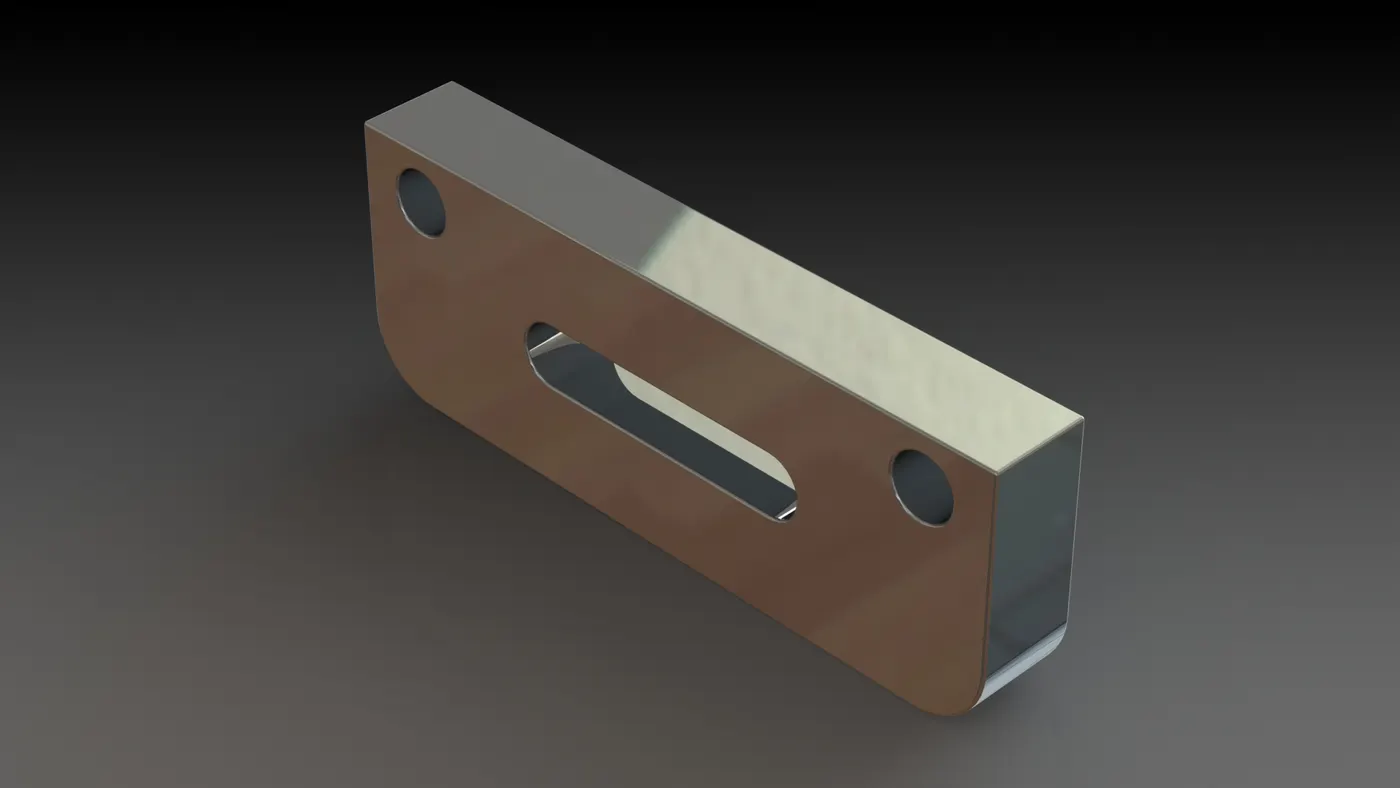
Procedure :
- Front Plane - Draw a sketch using lines, arc, circle and slot. Sketch a horizontal line about origin using midpoint option. Draw arcs and a vertical line on both sides of drwan horizontal line. Draw two circles and a slot at edges & center respectively.,Extrude it.
- Apply Fillet and give appearance.
2. Part 2 :
Feature Tools - Extruded Boss/Base & Fillet.
Sketch Tools - Sketch Geometry like - Line, Circle,rectangle & arc.
Render Image - PV 360
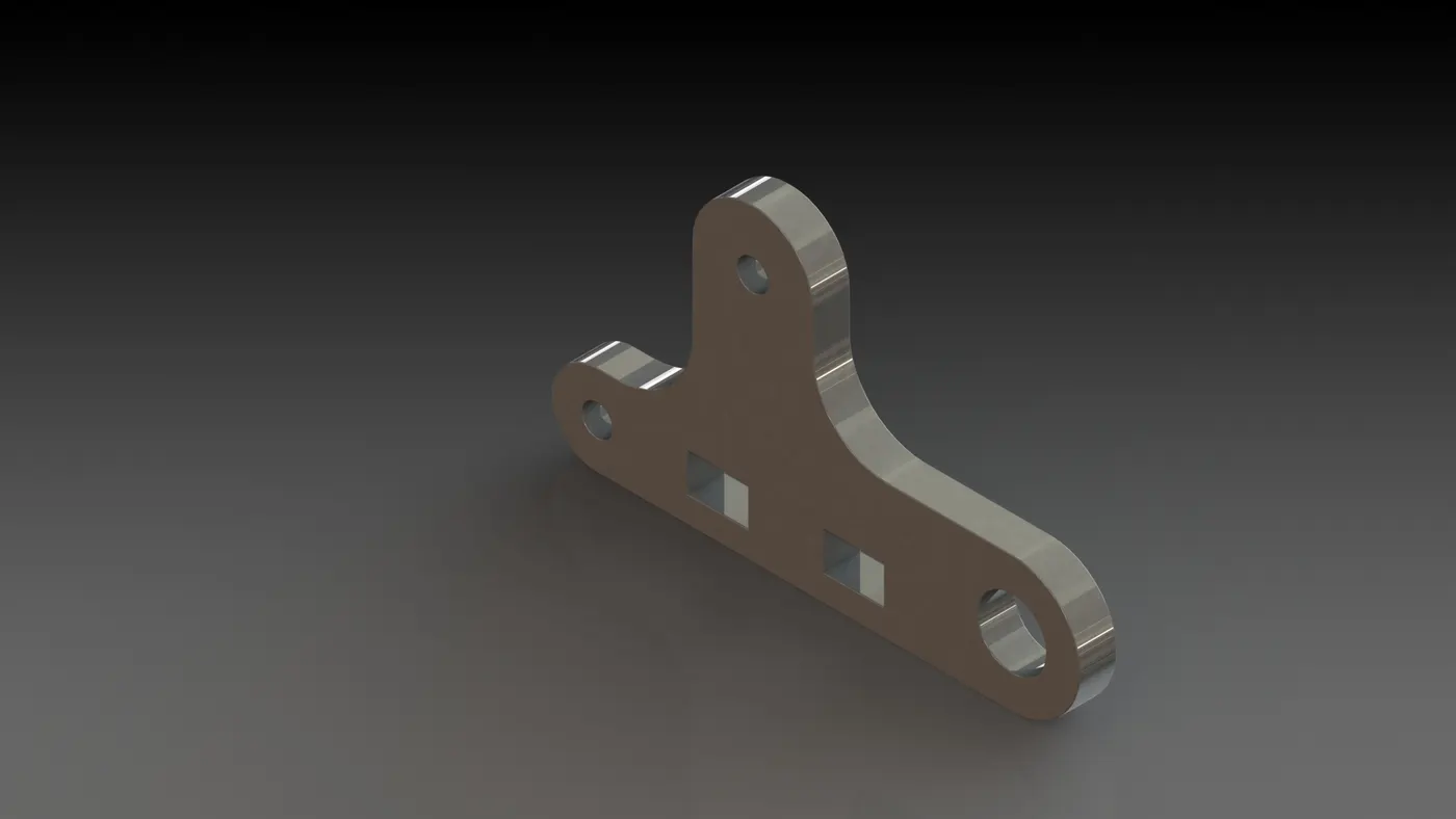
Procedure :
- Front Plane - Draw a horizontal line using midpoint option about origin. Sketch arcs connecting about horizontal line at both endpoints. Draw three circles one on left, one on right and on top of proper dimensions. Sketch two equal rectangles seperated by a distance from drawn horizontal line, connect the bottom drawn arcs with lines and lines., Extrude it.
- Apply fillet and give proper appearance.
3. Part 3 :
Feature Tools - Extruded Boss/Base, mirror & Fillet.
Sketch Tools - Sketch Geometry like - Line, Circle,rectangle.
Render Image - PV 360
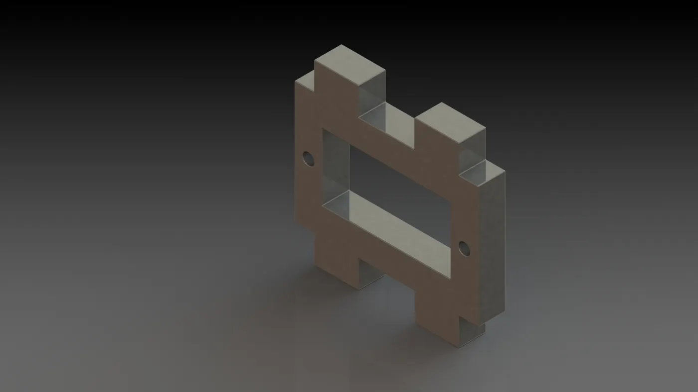
Procedure :
- Front Plane - Draw two rectangles at an offset from origin. Sketch one more rectangle at the top, coinciding with outer rectangle. Now mirror this rectangle about horizontal Construction line. Draw a circle in between above drawn offset rectangles. Mirror those rectangles which were previously mirrored about vertical construction line., Extrude it.
- Apply Fillet and give proper appearance.
4. Part 4 :
Feature Tools - Extruded Boss/Base, mirror & Fillet.
Sketch Tools - Sketch Geometry like - Line, Circle,rectangle, fillet & Linear Pattern.
Render Image - PV 360
Fillet - Creates a rounded internal/external face along one or more edges in solid or surface features.
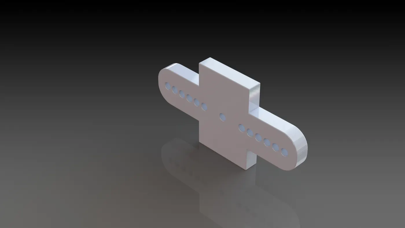
Procedure :
- Front Plane - Draw two rectangles about origin perpendicular to each other. Apply fillet of 3.5mm radius to horizontal rectangle and extrude it.
- Draw a circle on one of the face of above extrude and do linear pattern., do cut extrude.
- Mirror the above cut extrude about right plane.
- Apply fillet and give proper apperance.
5. Bottom Cover :
Feature Tools - Extruded Boss/Base, Extrude cut & Fillet.
Sketch Tools - Sketch Geometry like - Line, Circle,rectangle & Convert Entities,Trim entities.
Render Image - PV 360
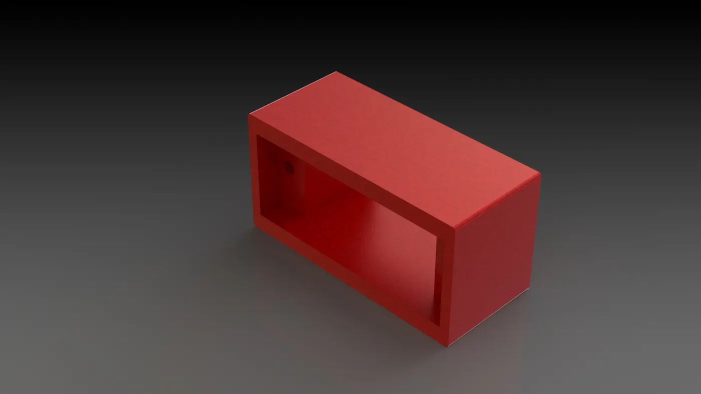
Procedure :
- Front Plane - Draw two rectangles at an offset of 2.5mm and extrude it. Apply fillet.
- Convert the inside ege using convert entity and draw two vertical lines to make as a rectangle, trim the extra entities and extrude it on above extrude face.
- Draw a circle on previous extrude and do cut extrude.
6. Intermediate Cover :
Feature Tools - Extruded Boss/Base & Fillet.
Sketch Tools - Sketch Geometry like - rectangle.
Render Image - PV 360
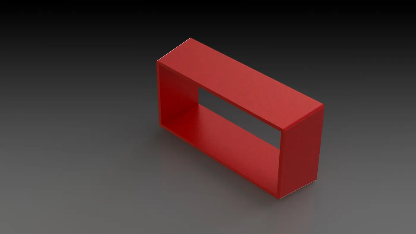
Procedure :
- Front Plane - Draw two rectangles at an offset of 2.5mm and extrude it with a draft of 5 degree.
- Apply fillet and give proper appearance.
7. Top Cover :
Feature Tools - Extruded Boss/Base, Extrude cut, Draft & Fillet.
Sketch Tools - Sketch Geometry like - Circle,rectangle.
Render Image - PV 360
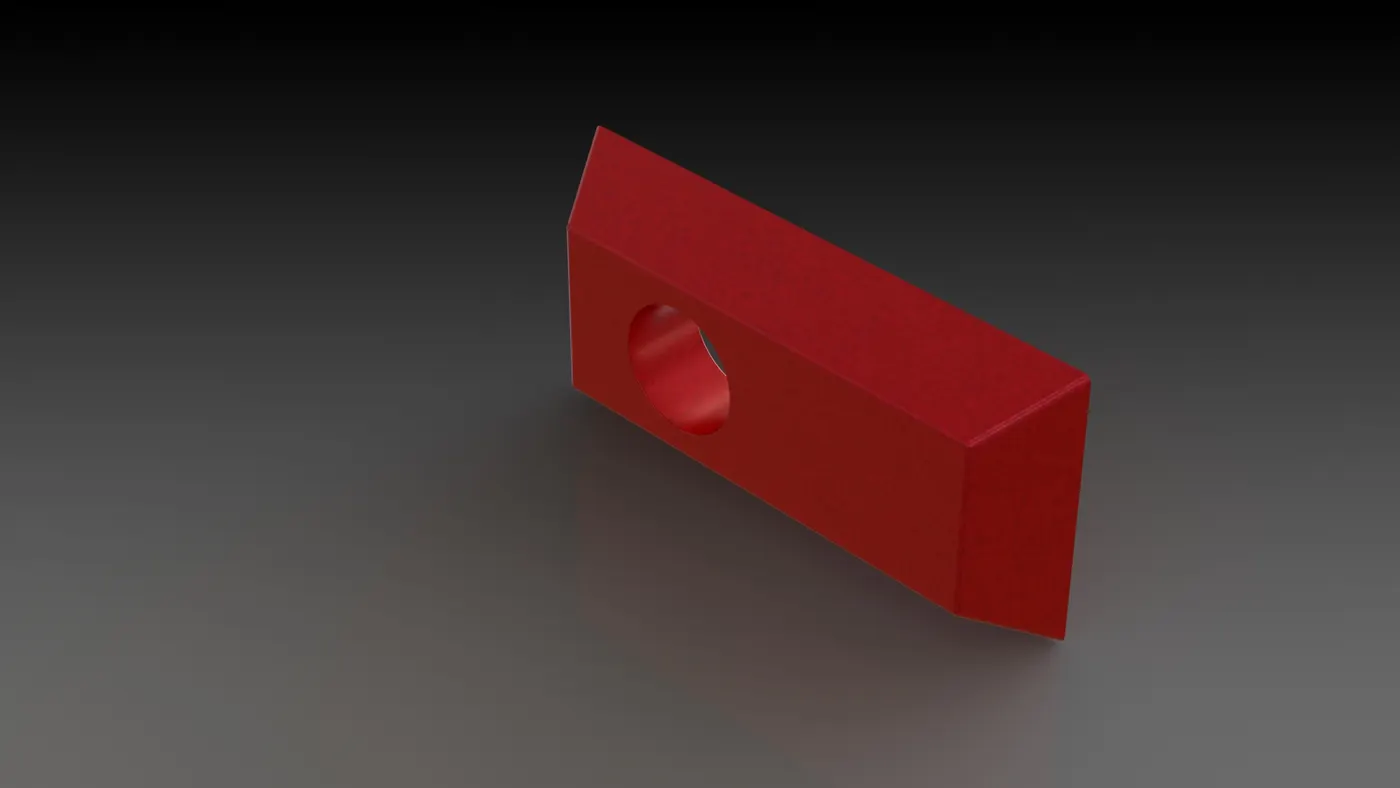
Procedure :
- Front Plane - Draw two rectangles at an offset and extrude it.
- Apply Draft by selecting Neutral plane and faces to draft, 30 degree draft angle.
- Draw a circle on above extrude and do cut extrude.
- Apply fillet and give appeaarance to it.
8. Drill Bit:
Feature Tools - Extruded Boss/Base, Extrude cut, Sweep cut, Helix, Circular Pattern & Revolved cut
Sketch Tools - Sketch Geometry like - Circle,Spline, line & Convert entities
Render Image - PV 360
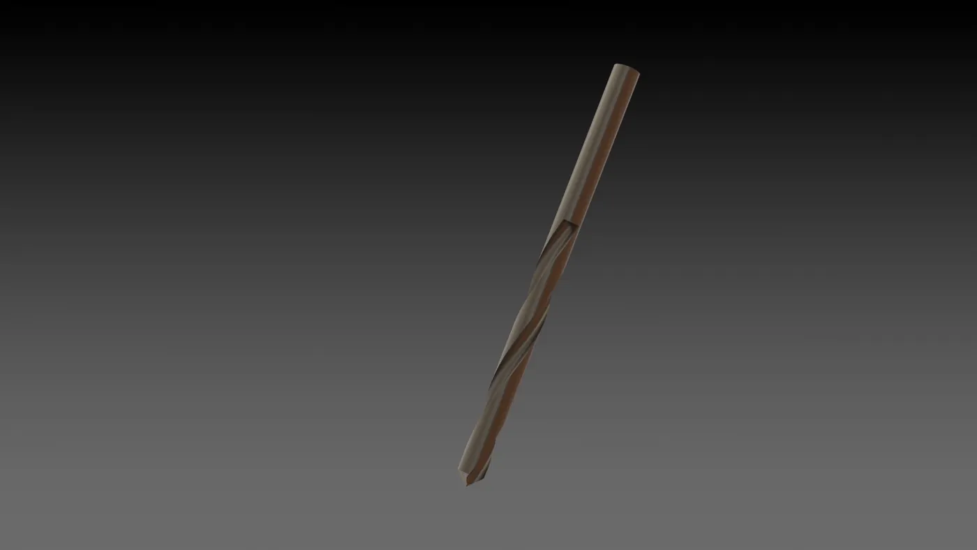
Procedure :
- Front Plane - Draw a circle and extrude it about origin.
- Convert the front face of above extrude using convert entities.
- Draw a Helix with reference to above sketch.
- Draw a circle at the end point of Helix and a spline on 3D Sketch., do sweep cut.
- Now select the face of above cut extrude and do circular pattern at 160 degree angle.
- Top Plane -Draw a vertical line at the bottom portion of above extrude make it constrution. Draw angled line at 45 degree , vertical and hozintal line connecting them. Do cut revolve about vertical line to form sharp edge.
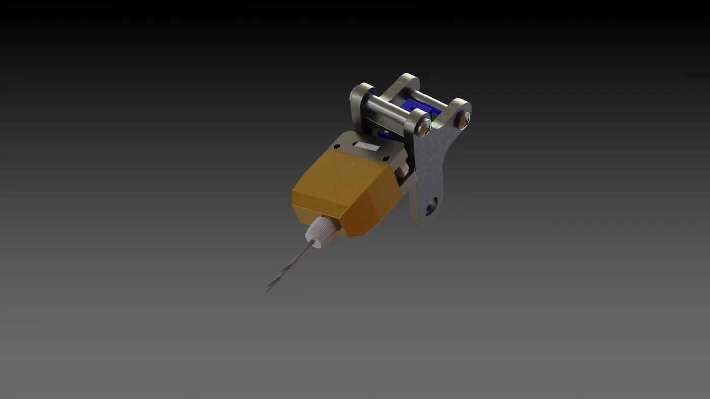
ii. Assembly of Designed Parts:
In this all designed components assembly together to obtain end effector.
Steps to be followed for Assembling -
- All Designed Parts to be inserted one by one as per requirement.
- Apply mate condition with respective parts for giving exact location in Assembly.
- Insert 2 Servomotors at proper location and make it work.
- Insert Pins, Screws & nuts at appropriate parts.
E. MODULE 5:
Attaching gripper to arm and then applying mates to it to obtain desired motion.
Steps to be followed for Assembling -
- All Designed Parts to be inserted one by one as per requirement.
- Apply mate condition with respective parts for giving exact location in Assembly.
- Insert Component - Adds an existing part or sub-assembly to the assembly.
- Mates - Position two components relative to one another.
Final Rendering:
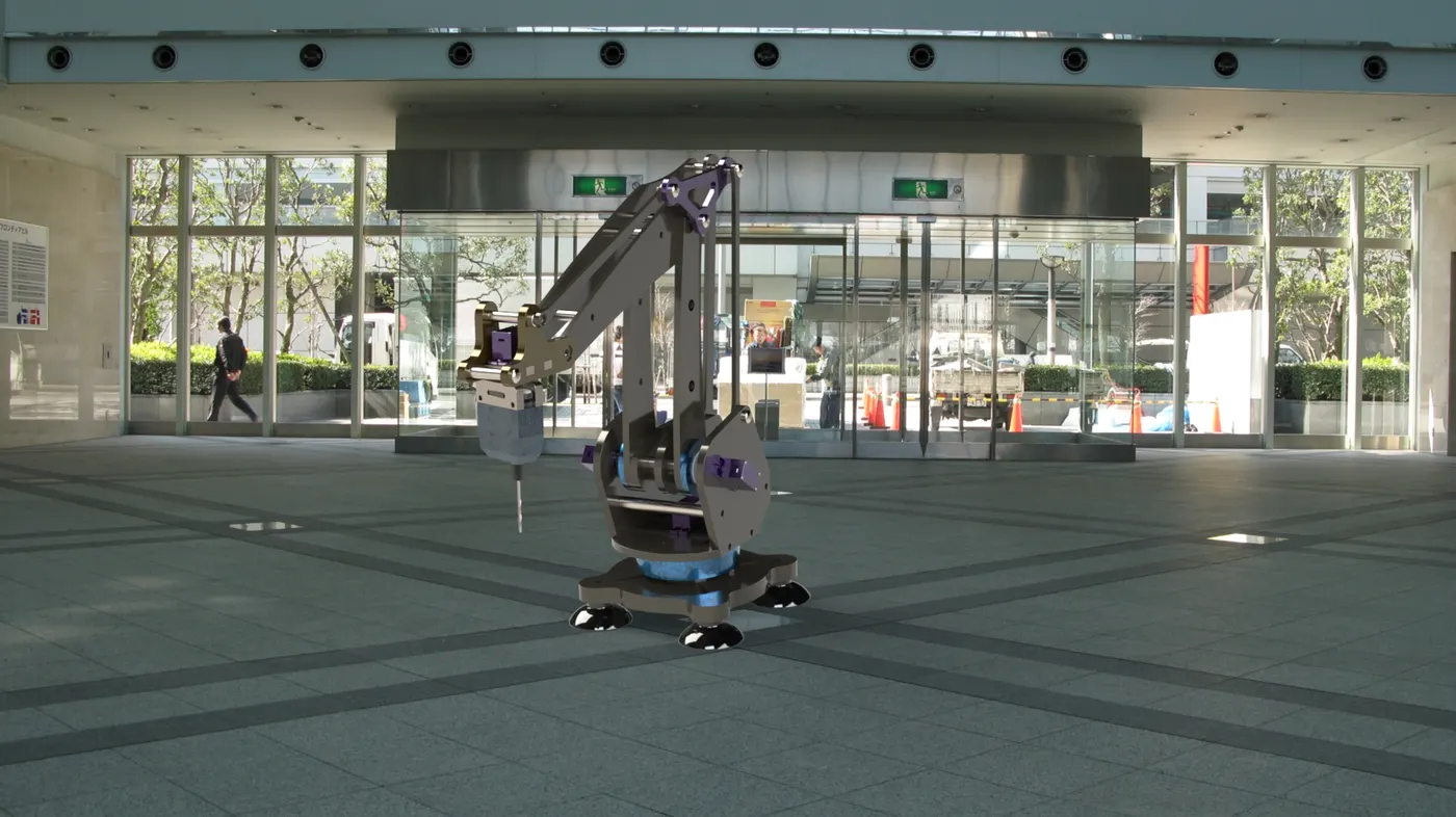
In this our Robotic Assembly rendered to make it more realistic using PV 360 & Solidworks Visualize.
Steps to follow-
- Import - Import assembly once created a new project.
- Appearance - Give appropriate appearances to various parts to make more attractive after rendering.
- Scenes - Use Proper Back Plates/Environment as scenes and drag the assembly at proper location.
- Output - Once done with all setup, a quick render help you out to review final output. Changes the colours by increasing/decreasing various values for better look (if required). Then go for final quallity rendering.
Conclusion:
At the end of Project each and every component of Robotic arm designed in various modules and assembled together in final module to obtain desired output. Camera setup & proper scenes were used to give more realistic appearance while final rendering.