DESIGINING OF BOX ASSEMBLY - NX SHEET METAL APPLICATION
Designing of Box Assembly - NX Sheet Metal Application
OBJECTIVE:
In this project we are going to design Box Assembly in NX using sheet metal application.
INTRODUCTION :
Sheet metal refers to metal that has a high surface area to volume ratio. Sheet metal work stock, used for sheet metal processes, is usually formed by rolling and comes in coils.
Box Assembly - A container with a flat base and sides, typically square or rectangular and having a lid. Box build assembly covers such a wide range of items that it differs each time when required by different people. It can be either as simple as putting items into simple enclosures with interfaces or displays or as complicated as system integrations containing thousands of individual components or sub assemblies.
DESIGN METHODOLOGY/APPROACH:
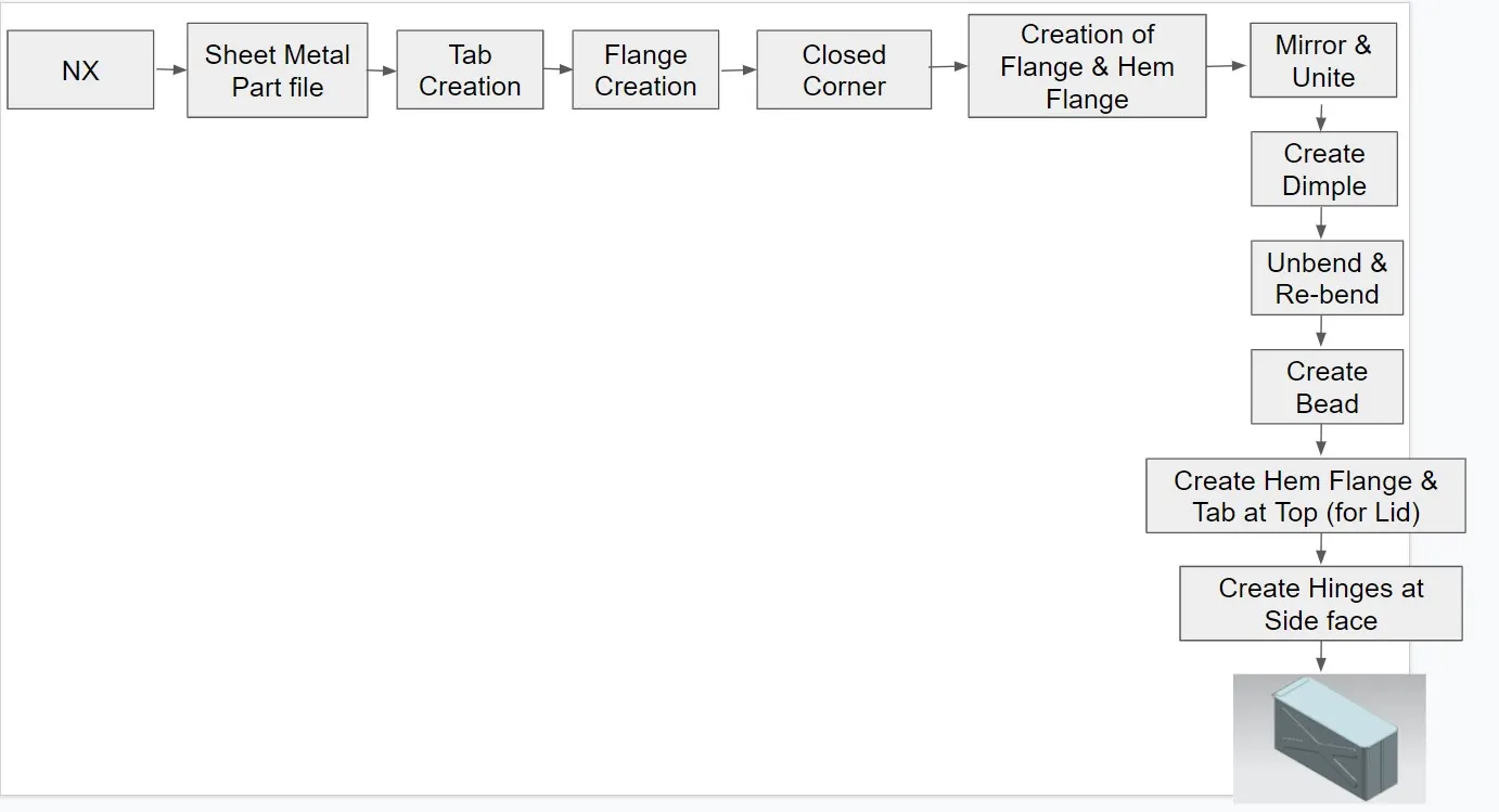
DESCRIPTION:
Application : Sheet metal
Sheet Metal- Starts the Sheet Metal application, which provides tools to design straight-brake and more complex sheet metal parts.
Feature Tools : Tab, Flange, Closed Corners, Hem Flange, Mirror Body, Unite, Dimple, Unbend, Re-bend, Bead, Datum Plane, Normal Cutout, Break Corners.
Tab - Create a base feature by extruding a sketch along a vector by a thickness value or adds material to a planar face. Additional Planar sections can be added to generate bends as part of the base feature.
Normal Cutout - Cuts material by projecting a sketch onto the model and them cutting perpendicular to the faces intersected by the Projection.
Flange - Adds a flat flange at an angle to a planar face and adds a bend between the two.
Closed Corner - Closes a corner where two adjacent flanges meet by extending the bends and flanges.
Unbend - Flattens a bend and the material adjacent to the bend.
Mirror body - Adds a hole to one or more solid bodies in a part or assembly with options for counterbored, countersunk and threaded.
Dimple - Lifts an area of the model inside a sketch that simulates a stamping tool.
Bead - Lifts a material along the contour of a sketch that simulates a stamping tool.
Re-bend - Restores an unbend feature to its previous bent state, along with any features added after the unbend feature.
Unite - Combines the volume of two or more solid bodies into a single body.
Hem Flange - Modifies the model by folding the edge of sheet metal flange over onto itself for the purpose of safe handling or to increase edge stiffness.
Datum Plane - Creates a datum plane used to construct other features.
Break Corner - Rounds or chamfers a sharp corner of a tab or flange.
PROCEDURE:
1. Open a new Sheet Metal Part file and save it as Box Assembly.prt
2. Tab Creation :
- XY Plane - Create a sketch by drawing a symmetric rectangle wrt X axis at origin. Exit the sketch mode.
- Change the design Parameters as per requirement.
- Use Tab feature to create a rectangular metal sheet.
3. Flange Creation:
- Use Flange Feature and select approriate edges to create flanges normal to XY & XZ Plane respectively.
4. Closed Corners:
- Use Closed Corner and select bends of adjacent flanges to close the corners.
5. Flange Creation:
- Use Flange Feature and select the edge of previously created flange.
- Create one more flange using above flange edge.
6. Repeat Step 4 & Step 5 on other side.
7. Hem Flange Creation:
- Create a open type Hem flange by selecting edge of flange created in step 5.
8. Do the same on the other edge too.
9. Mirror Body:
- Select the Created body and mirror it about YZ Plane.
10. Unite:
- Use the two bodies (Created & mirror body) to unite.
11. Dimple Creation (Side face):
- Select the Side face of the Box and Create a sketch in the shape of "X". Apply sketch fillets to the edges to round the corners and connecting edges.
- Use Dimple feature to create a stamp on it.
12. Mirror the above created dimple about XZ Plane using Mirror feature.
13. Dimple Creation (Bottom face):
- Select the Bottom face of the Box and Create a sketch using rectangle. Apply sketch fillets to the edges to round the corners.
- Use Dimple feature to create a stamp on it.
14. Bead Creation (Bottom face):
- Select the Bottom face of the Box and Create a sketch using Circle.
- Use Bead feature to create a stamp on it.
15. Mirror the above created dimple about X & Y Axis using Mirror feature.
16. Hem Flange Creation (Top face):
- Select the top edges and use Closed type Hem flange to fold the material.
17. Lid Creation (Top face):
- Create a Datum plane at an offset of 203mm from bottom face.
- Now sketch on newly created plane using lines and arcs in such a way that it forms a lid shape.
- Use Tab feature and select the sketch to create Lid.
- Extend the edges of lid by using Flange feature.
18. Hinge Creation (Side face):
- Create a Sketch on side face by drawing a rectangle. Exit the Sketch.
- Create a Tab by selecting above sketch.
- Use Break corners and select the bottom left edge to round it.
- Create a flange at an angle by selecting edge of previously extruded Tab.
- Now use Open loop type Hem. flange by slelecting proper edge to create a fold.
- Unbend the fold and created a sketch by drawing few rectangle. Exit the Sketch and do Normal cutout.
- Rebend the fold.
19. Now Mirror the Hinge about XZ Plane.
20. Hinge Creation (Top face):
- Create a Sketch on top face by drawing a rectangle. Exit the Sketch.
- Create a Tab by selecting above sketch.
- Use Break corners and select the top left & right edges to round it.
- Create a flange at an angle by selecting edge of previously extruded Tab.
- Now use Open loop type Hem. flange by slelecting proper edge to create a fold.
- Unbend the fold and created a sketch by drawing few rectangle. Exit the Sketch and do Normal cutout.
- Rebend the fold.
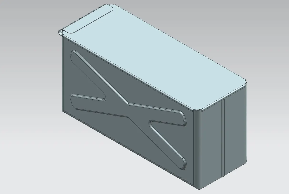
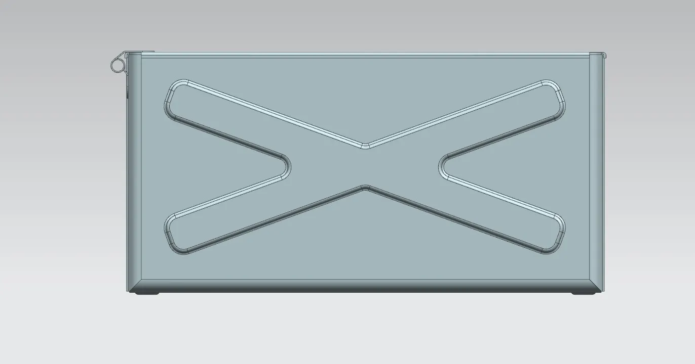
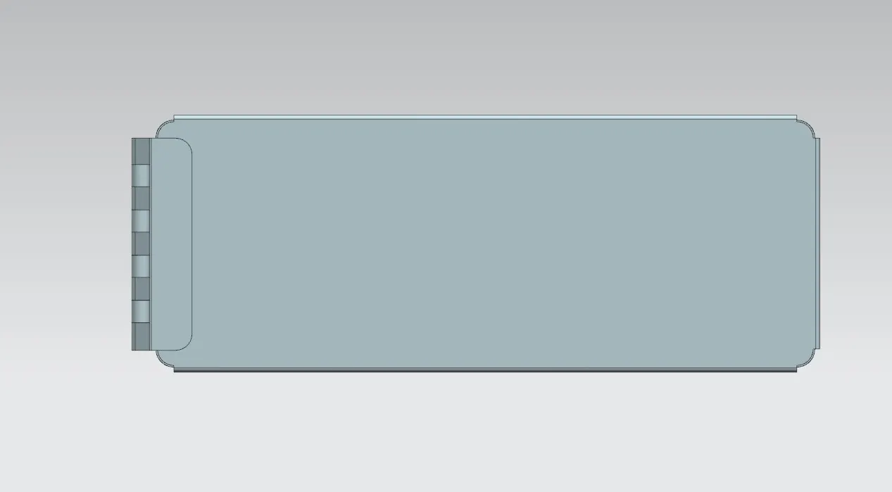
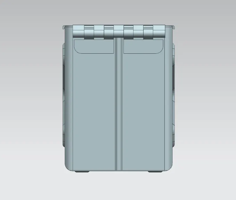
CONCLUSION:
At the end Box Assembly Designed in NX cad using Sheet metal as application. Adding/removing of material done to give proper strength/stiffness to the component.