DESIGNING OF CASING - NX SHEET METAL APLLICATION
Designing of Casing - NX Sheet Metal Application
OBJECTIVE:
In this project we are going to design Casing in NX using sheet metal application.
INTRODUCTION :
Sheet metal refers to metal that has a high surface area to volume ratio. Sheet metal work stock, used for sheet metal processes, is usually formed by rolling and comes in coils.
Casing - A Casing is usually used as an outer cover: a shell casing or tire casing,the frame or framework for a window or door, a metal pipe or tube used as a lining for a water, oil, or gas well.
DESIGN METHODOLOGY/APPROACH:
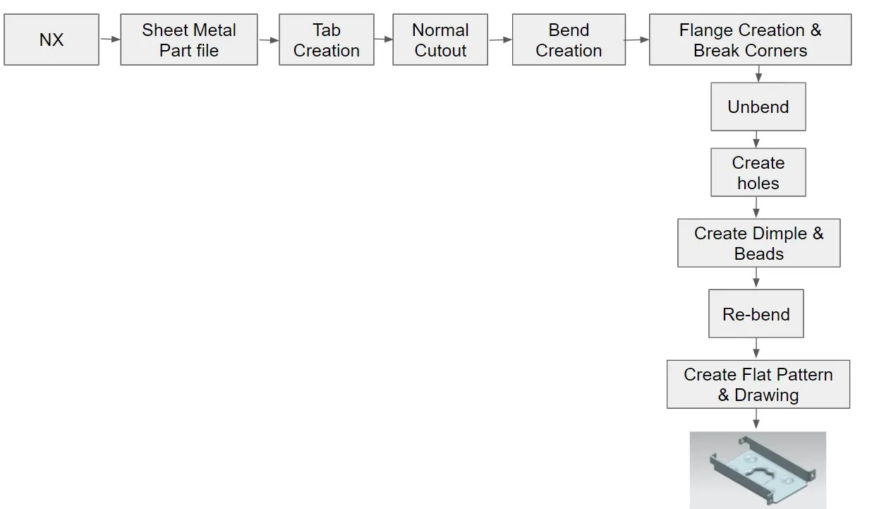
DESCRIPTION:
Application : Sheet metal, Drafting.
A. Sheet Metal- Starts the Sheet Metal application, which provides tools to design straight-brake and more complex sheet metal parts.
Feature Tools : Tab, Normal Cutout, Bend, Flange, Break Corners,Unbend, Hole, Dimple, Bead, Re-bend, Flat Pattern.
Tab - Create a base feature by extruding a sketch along a vector by a thickness value or adds material to a planar face. Additional Planar sections can be added to generate bends as part of the base feature.
Normal Cutout - Cuts material by projecting a sketch onto the model and them cutting perpendicular to the faces intersected by the Projection.
Flange - Adds a flat flange at an angle to a planar face and adds a bend between the two.
Bend - Modifies the model by bending material on one side of one side of a sketch line, adding a bend between the two sides.
Break Corner - Rounds or chamfers a sharp corner of a tab or flange.
Unbend - Flattens a bend and the material adjacent to the bend.
Hole - Adds a hole to one or more solid bodies in a part or assembly with options for counterbored, countersunk and threaded.
Dimple - Lifts an area of the model inside a sketch that simulates a stamping tool.
Bead - Lifts a material along the contour of a sketch that simulates a stamping tool.
Re-bend - Restores an unbend feature to its previous bent state, along with any features added after the unbend feature.
Flat pattern - Creates a flat pattern from the formed sheet metal part.
B. Drafting - Starts the Drafting application, which provides tools to create and maintain drawings of the design model
Feature Tools: New Sheet, Base View.
New Sheet - Creates a new drawing sheet.
Base View - Creates a model based view on the drawing sheet.
PROCEDURE:
1. Open a new Sheet Metal Part file and save it as Casing.prt
2. Tab Creation :
- XY Plane - Create a sketch by drawing a centred rectangle at origin. Exit the sketch mode.
- Change the design Parameters as per requirement.
- Use Tab feature to create a rectangular metal sheet.
3. Normal Cutout:
- XY Plane - Create one more sketch by drawing a symmetric rectangle w.r.t X-axis and coincindent it with left edge of sheet metal. Exit the mode.
- Use Cutout feature to create a rectangular hole in the Sheet.
4. Bending:
- XY Plane - Again create a sketch by drawing a symmetric lines w.r.t X-axis, dimension it from upper horizontal sheet metal edge. Exit the mode.
- Use Bend feature and select drawn line, mention bend angle to bend.
- Repeat the same feature one another side.
5. Flange:
- Use Flange Feature and select approriate edges to create flanges.
6. Breaking Corners:
- Apply fillets to the required edges by using Break corners feature.
7. Unbend Sheet Metal:
- Unbend the sheet metal by selecting stationary face as larger face & bend faces to bend.
8. Adding Holes:
- XY Plane - Create a sketch by drawing a line and sketch point at the lower left part of the sheet metal. Create a symmetric of that w.r.t X axis.
- Repeat same procedure at the other edge.
- Use Hole feature to create holes.
9. Adding Dimple:
- XY Plane - Create a sketch by drawing horizontal and vertical lines.
- Use Studio Spline by selecting poles to create spline by dragging endpoints in above sketch.
- Use Move Curve to move set of curves and adjust the adjacent curves to accomodate by selecting previous curve.
- Now add Dimple by giving required dimple properties.
10. Adding Bead:
- XY Plane - Create a sketch by drawing Circle at the required portion.
- Use bead feature to create a stamp by selecting above drawn circle.
- Use Mirror feature to mirror about YZ & XZ Plane.
11. Re-bend Sheet Metal:
- Re-bend the sheet metal by selecting Bend face which is previously used to un bend.
12. Drafting:
- Use Flat Pattern and select the flat face to create flat pattern.
- Create a new drafting file of A4 Size and add Base view by giving proper scale(Rotate the model if required).
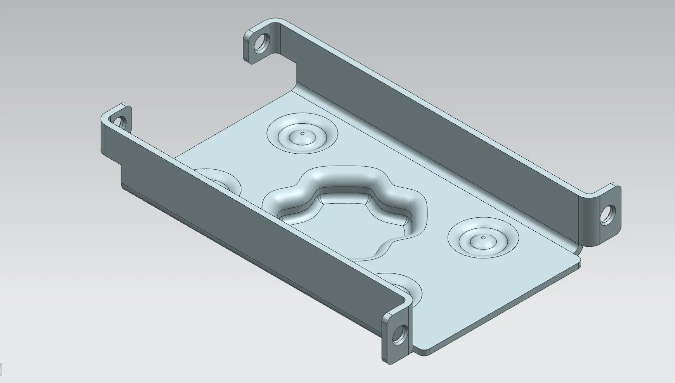
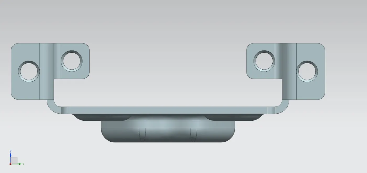
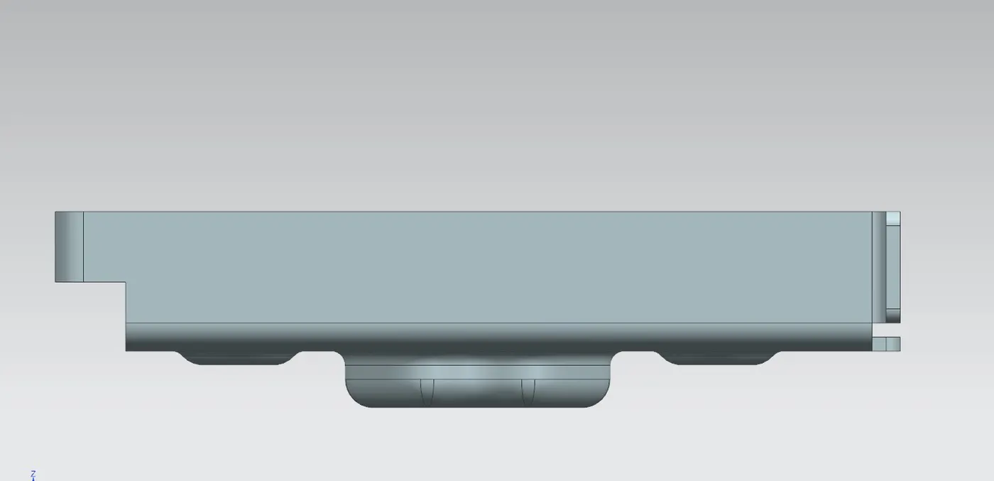
Final Image of Casing:
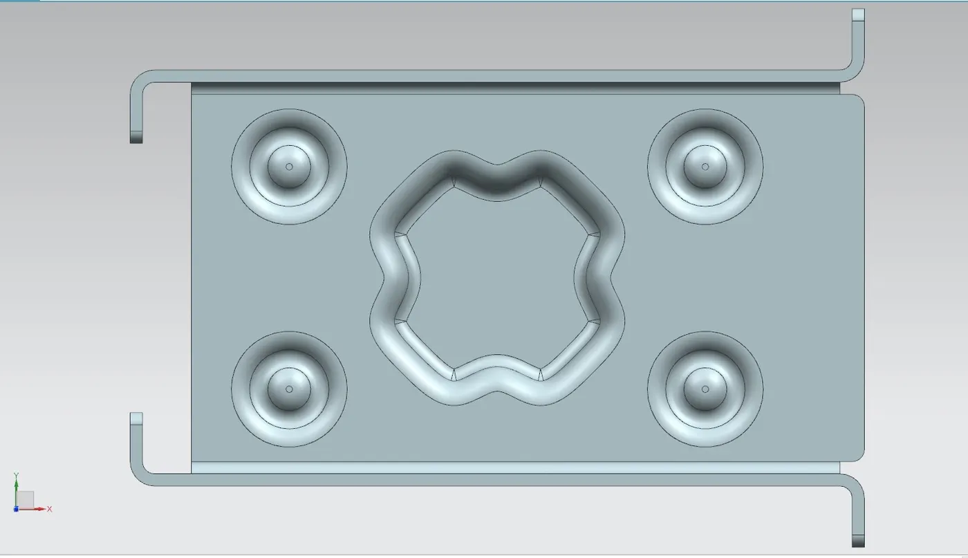
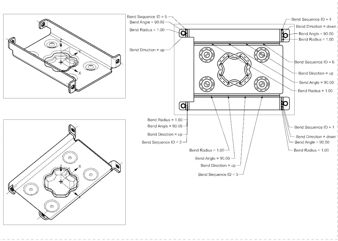
CONCLUSION:
At the end Casing Designed in NX cad using Sheet metal as application. Adding/removing of the material done to give proper strength to component.