Hood design-Week 2
Aim:
To design Hood with the following requirements
- Design Outer Panel with the Hem
- Develop the Inner Panel
- Develop all the Necessary Reinforcements
- Mirror and position the Hinge & Striker
- Provide Mastic Data
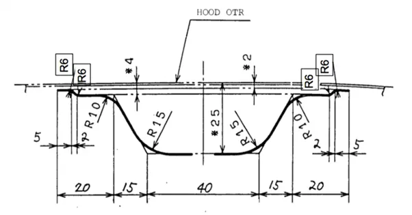
- Provide the required Emboss definition
Tool used- NX 12
Theory- A car hood also referred to as a bonnet is a hinged cover that rests over the engine of a vehicle. Its purpose is to provide access to the engine for repair and maintenance. A concealed latch is typically used to hold down the hood. On vehicles with an aftermarket hood and on race cars, hood pins may be used to hold down the car hood
The following are the guidelines should be considered while designing the hood
- Outer Panel Thickness = 0.75mm
- Inner Panel Thickness = 0.75mm
- Reinforcement Thickness = 1 mm
- Minimum fillet radius = 3mm+thickness
- No sharp edges
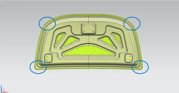
- Provide proper corner relief
- Emboss maximum depth =6-10mm
Data to be used:
Hood Thickness Information
- Outer Panel Thickness = 0.75mm
- Inner Panel Thickness = 0.75mm
- Reinforcement Thickness = 1mm
Master sketch (INPUT):
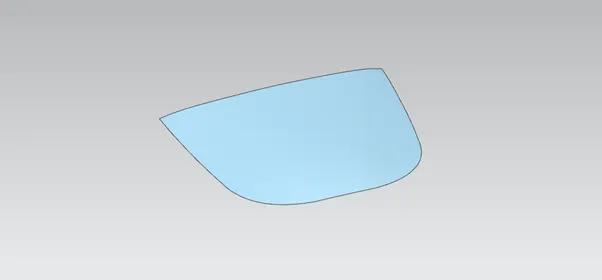
Outer Panel (INPUT):
FEATURES USED IN DESIGNING THE HOOD:
- Offset surface
This feature is used to offset the surface with respect to direction and dimensions. For this we need to select the surface then offset the surface with the direction and dimensions.
- Trim sheet
This feature is used to cut the surfaces. For this command we need to draw a reference line as the trim tool. After cutting the body, we can keep or remove the cut surface by selecting the keep or discard selections.
- Offset curve in face:
This tool is used to draw line on the selected surface with the offset distance.
- Project Curve:
This feature is used project 2D sketches and curves on the selected surface with reference to the direction. First we need to draw the sketch or the curves on the plane, then we need to select the sketch and the face to be projected with the vector direction.
- Edge blend:
This feature is used to make blend for the edge of the surface. For this we need to select the edge with the continuity and the radius for the blend.
- Face blend
This feature is used to make blend for the un-sewed surfaces and makes them sewed.
- Emboss:
This is a very handy feature. In this we need to draw a sketch and project to the surface and we should select the feature and select the sketch, offset distance and the angle for the surface connection. As the result, it will offset the specified surface and makes a connecting surface with respect to the angle.
- Law extension:
This feature helps us to extend the edges or curves in the specified direction and can also extends with respect to the angle.
- Mirror geometry
This feature is used to mirror any sketches and features with respect to the axis.
- Thicken:
This feature is used to thicken the surfaces to make them to the sheet bodies. We just need to select the surface body and give the direction.
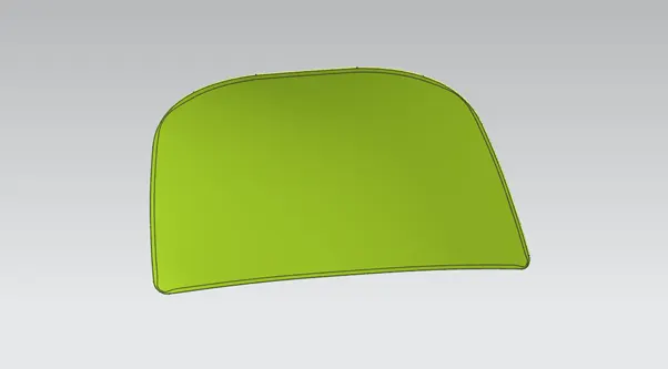
Design Outer Panel with the Hem:
Hemming data:
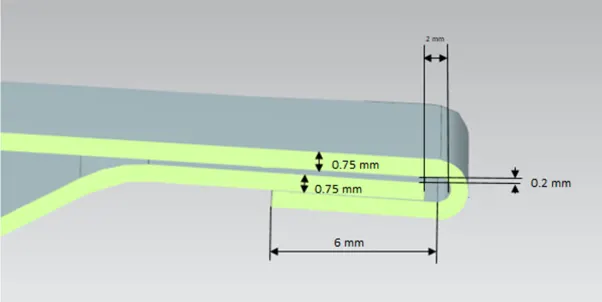
It is used for joining the inner and outer panel. It is used in place of spot welding which reduces lots of loss.
When force is applied during Hemming there may be a change of shape which is examined and relaxation is given in those areas.
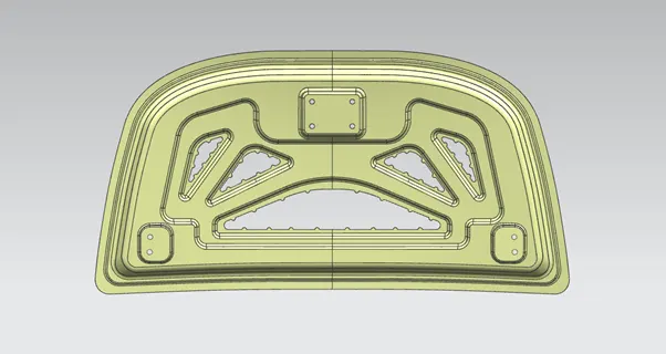
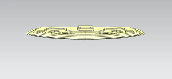
Design of inner panel-
Designed according to the given dimensions and by using the thickness as 0.75.
Corner Relief-
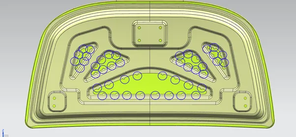
Mastic pads:
Sealants are materials that are for one-time use only. Mastic sealants are widely used in the automotive industry. Mastic is commonly used on construction projects as an adhesive and sealant. It is a popular choice where one surface needs to be adhered to another in a durable bond, or where the area needs to be protected.
Embossing:
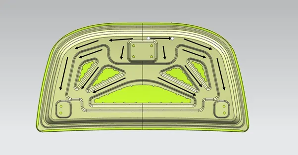
Sheet metal embossing is a stamping process for producing raised or sunken designs or relief in the sheet metal. This process can be made by means of matched male and female roller dies or by-passing sheet or a strip of metal between rolls of the desired pattern. It is often combined with foil stamping to create a shiny, 3D effect. To provide strength to the inner panel and to distribute the forces produced during the impact with pedestrian or other obstacles to ensure the safety of the passengers. The forces are directed outwards through the embossing path.
Final Assembly-
Latch and striker positioning:
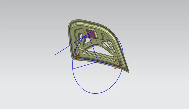
After positioning the hinge assembly and latch the position of the striker need to reset. The trajectory is derived from the hinge axis and the center distance from the striker. It is denoted as a circle. The hood closes properly if the striker is perpendicular to the trajectory.
Conclusion:
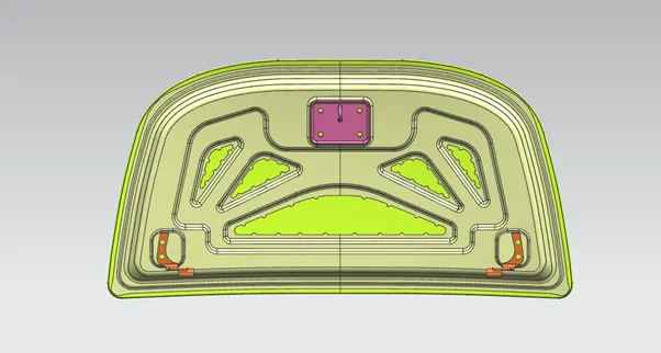
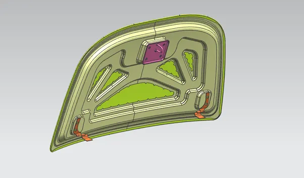
I learned to design of Hood or Bonnet that satisfies the industry manufacturing, functional requirements and as well as Euro NCAP (New Car Assessment Program) standards which defines the automotive safety regulations.