Hood design-Week 2
OBJECTIVE:
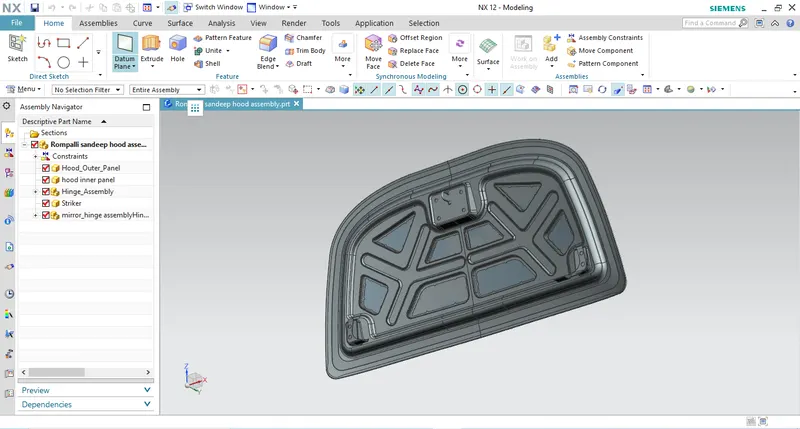
The main objective of this project is to design the Hood of a car that satisfies the manufacturing requirements, functional requirements, and as well as Euro NCAP standards. The Body in white (BIW) inner panel and outer panel of the hood must be designed and assembled with the Hinge Assembly, Latch and Striker with their reinforcements.
INTRODUCTION:
A car hood, also referred to as a bonnet in some other countries, is the hinged cover that rests over the engine of a front-engine vehicle. Its purpose is to provide access to the engine for repair and maintenance. A concealed latch is typically used to hold down the hood. On vehicles with an aftermarket hood and on racecars, hood pins may be used to hold down the car hood. Hoods sometimes also contain a hood scoop, wiper jets, power bulge, and/or hood ornament. Car hoods are typically constructed from steel and sometimes from aluminum. Aftermarket car hoods may be constructed from various other materials, including carbon fiber, fiberglass, or dry carbon.
DESIGN FLOWCHART:
- Create an assembly file.
- Importing the outer styling panel.
- Design inner panel.
- Importing the hinge and striker.
- Adding constraints for hinge and striker.
- Creating a hem flange.
COMPONENTS OF HOOD:
- Inner Panel
- Outer Panel
- Hinge
- Striker
HOOD ASSEMBLY:
- First the neutral data file of the styling surface was extracted.
- Then by keeping it as a parent file two work surface was created and named separately as hood inner panel and outer panel.
- Then in assembly navigator a new assembly was created and the parts and sub-assemblies were added into it.
- After creating the inner panel and outer panel the hinge assembly and latch will be constrained.
HOOD INNER PANEL:
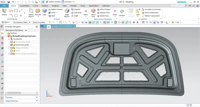
- By using the wave geometry linker the styling surface will be extracted as a linked body.
- The styling surface was trimmed into half using the trim surface along x co-ordinate.
- Then two surfaces at the offset of 0mm were generated and one feature grouped as parent file and the other one was used as the working surface.
- By using the master sketch three surfaces were off-set at a distance of 2mm, 4mm and 25mm downwards.
- For creating the 5mm flange the corner of the tangent curve will be offset inwards at the distance of 20mm with a 30mm filleted corner and the remaining portion was trimmed.
- Then for creating the next flange the second offset surface was trimmed at a distance of 40mm.
- By using through curves both the surface were connected to create a flange at an outward angle of 80 degree as per the manufacturing parameter.
- Then the third surface was trimmed and used to create the flange at the distance of 55mm.
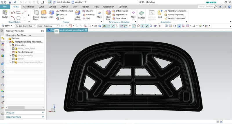
- Then the required embosses were created to reduce the transmission of force and it should satisfy the requirements of NASC regulations and the embosses must have a outward draft to satisfy the tooling direction.
- Below diagram represents the ideology of the design, the orange line represents the direction of force dissipation when the hood attempts an unexpected crash.
- Then by using the edge blend and face blend all the sharp corners were blended and smoothened out as per manufacture requirements.
HOOD OUTER PANEL:
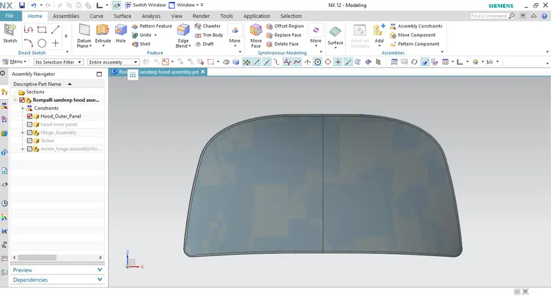
- The hood outer panel was created by creating an offset surface from the styling surface and then trimmed into half.
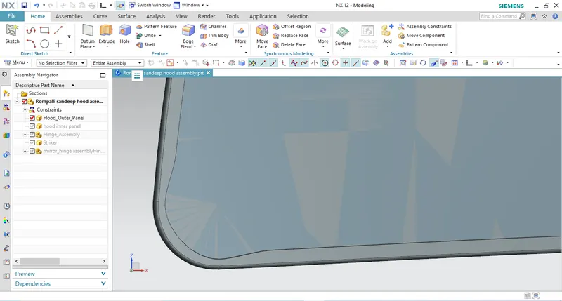
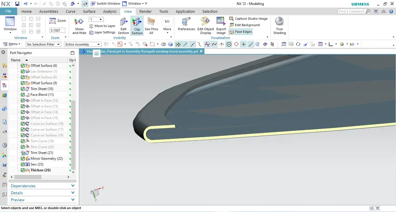
- Then for creating the Hem flange about 6mm around the outer panel for creating the hold with the inner panel.
- Then law extensions were used on the outside curve and the generated surface was offset to 6mm and then the remaining portions were trimmed.
- By using the Face blend the hem flange were created.
- By using the curve on surface and trim sheet the required corner relief was provided on the top and bottom corner as requirement.
- Now the other half was mirrored and sewed together.
- Below figures will show the section view of the hood assembly which explains the tolerance, smoothness, and face intersections were achieved as per the manufacturing requirements.
HINGE ASSEMBLY:
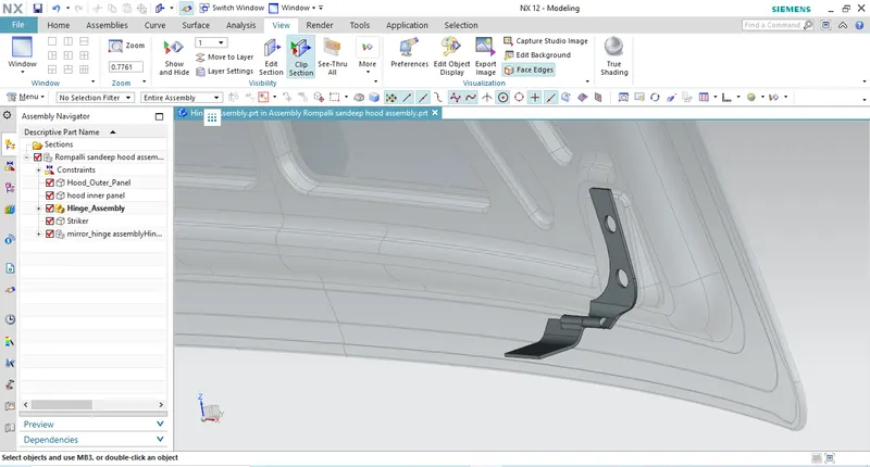
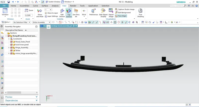
- The hinge assembly were positioned by applying the required constraints.
- First the inner panel was fixed and then a line was created horizontally connecting the hinges and then the hinges were constrained with a parallel mate.
- The back surface on the hinge hood part was touch/allign with the top surface of the hinge emboss on the inner panel.
STRIKER ASSMEBLY:
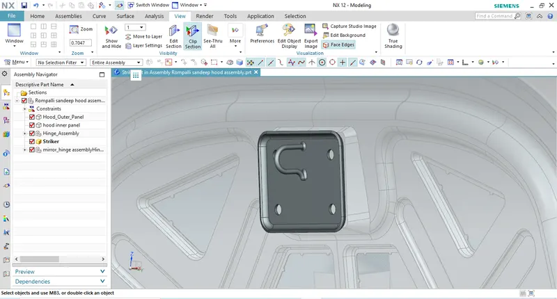
- First the latch was positioned roughly using the constraints and by exporting the back surface of the latch using wave geometry linker.
- Then by using the linked surface the emboss for the latch was created but before doing that the linked surface must be extended all around for creating a clearance for the edge blends.
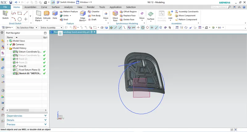
- Now the required circle from the center point of the hinge axis was created and a line tangent to the circle and a line vertical to the striker point from the latch were created.
- Now both the lines were aligned together and then the latch will have its perfect position for striking with the engine compartment.
CONCLUSION:
Finally the Body in white Hood of a car was designed as per the industrial manufacturing requirements following the Euro NCAP standards.