HOOD DESIGN
AIM : Designing of car’s hood and assembly of latch and hinges on hood.
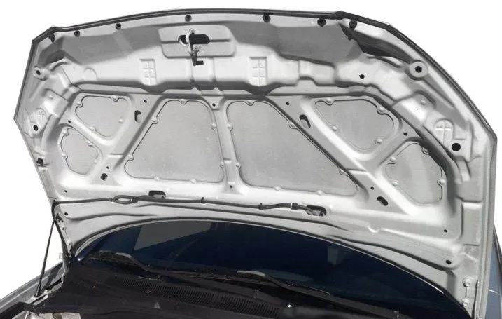
THEORY :
HOOD
- A car hood, also referred to as a bonnet in some other countries, is the hinged cover that rests over the engine of a front-engine vehicle.
- Its purpose is to provide access to the engine for repair and maintenance.
- Hood consists of outer and inner panels.
- Outer panel is for the aesthetic look of the hood and the inner panel has engineering features to hold the outer panel and help as force distribution when the car is exposed to accident.
LATCH & STRIKER
- Latch & striker is used for locking the hood with the car. it's usually placed on the space provided on the inner panel.
HINGE
- Hinges are used to connect the hood & cowl panel of an automobile. it enables the opening & closing operation of the hood. The hinge should be made strong enough to handle the weight of the hood and also to handle the force action on it during the collision.
HEMMING
- The outer panel & Inner panel can't be joined by the welding process as it will leave a spot on the outer panel and it will spoil the look of a car.
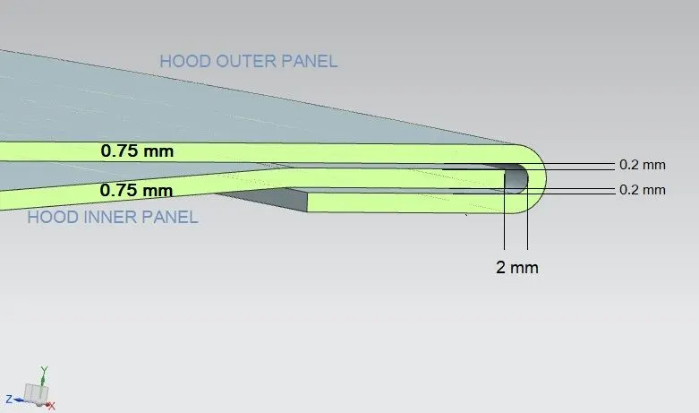
- Inner and outer closure panels together we use the Hemming process. It is the process of bending/folding the flange of the outer panel over the inner one. The flange of the outer panel is bent over the inner panel in progressive steps by means of the roller hemming head.
CORNER RELIEF TO OUTER PANEL FLANGE
- In the hemming process rollers are used. In this process the rollers will be rolling over the edges of the Outer panel to close it with the inner panel.
- These rollers will be rolling over 2-3 times for perfect closing.
- Force is being used by rollers to all the corners but there are some areas where the roller cannot tighten the part properly as we give some relief to the corners.
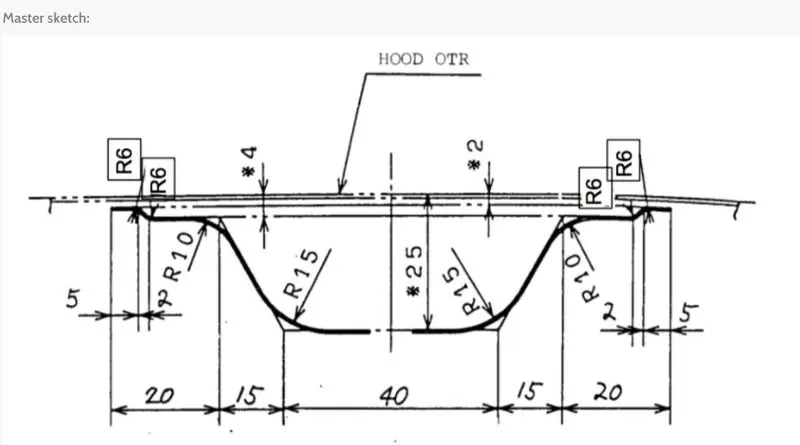
MASTER SECTION OF THE HOOD
APPROACH TO WORK ON PROJECT :
- Designing Outer Panel of the hood.
- Designing Inner Panel of the hood.
- Creating Hinge Emboss.
- Constraining the Hood Components.
- Creating Striker’s Emboss.
- Creating Holes for the Hinges Assembly on Inner Panel.
- Providing Reinforcement to latch and both the Hinges.
- Draft Analysis on Inner Panel.
Procedure in Constraining Hood Components.
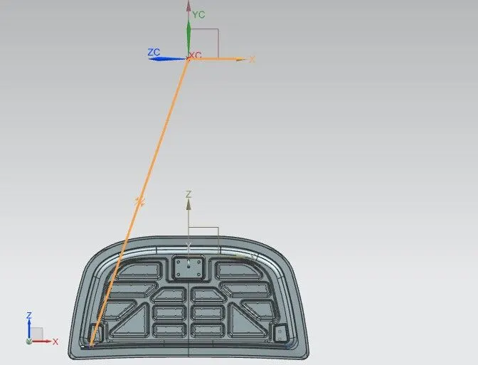
- Creating Centerline from Hinge Axis on HingePart Assembly
- Creating Trajectory of the Striker on Inner Panel Part.
- Creating Centerline from the Striker.
DESIGN OF OUTER PANEL OF THE HOOD :
- Given Hood Initial Surface, This is the surface provided which will be our working surface.
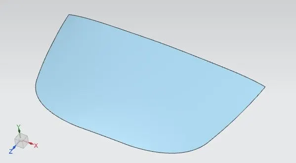
STEP 1 : Trim the Working surface into half by trim body command through Y axis or YZ Plane.
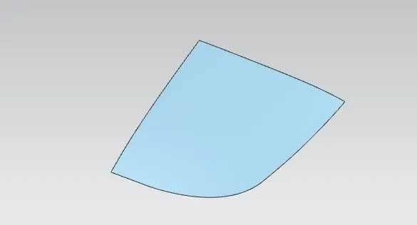
STEP 2 : We’ll start with a hemming flange that has to take an offset curve in the face of 0.5mm and to avoid sharp corners, have to provide 30mm of fillet.
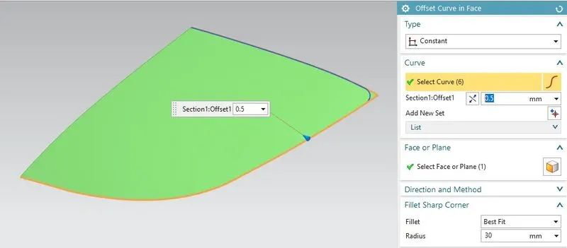
STEP 3 : By using law extension we’ll extrude the curve as shown in figure.
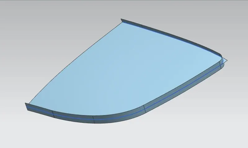
STEP 4 : Offsetting the surface to 10 mm.
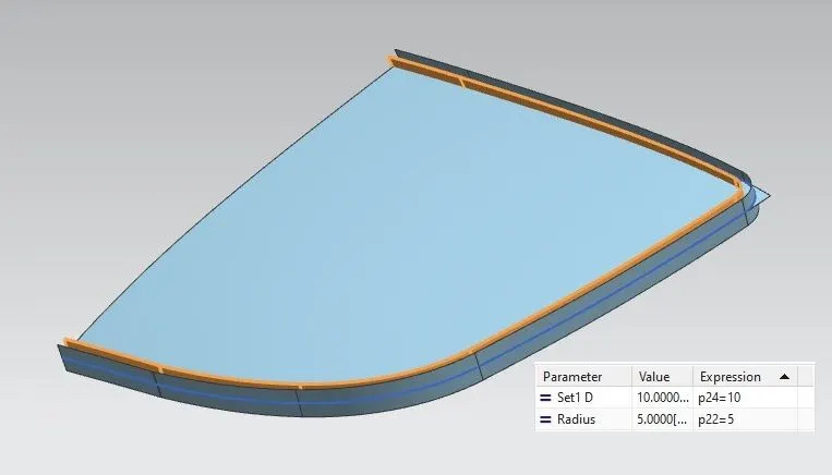
STEP 5 : Offsetting the working surface to 2.65 mm towards the downward direction of the working surface to create the end of the outer panel flange.
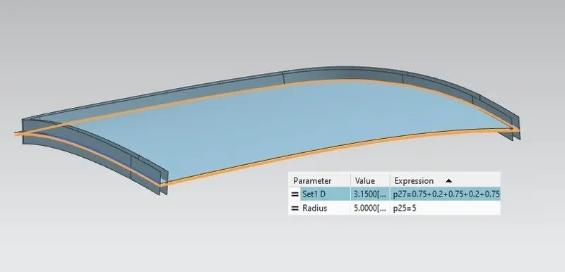
STEP 6 : Trim the sheet by the 10mm offsetted surface as shown below.
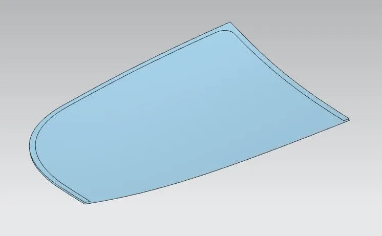
STEP 7 : Now we’ve to prove face blend command to all the remaining sheets to create a hemming flange.
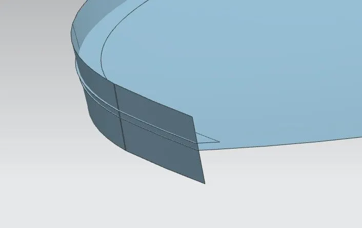
- After the face blend the outer panel can be seen in the figure below.
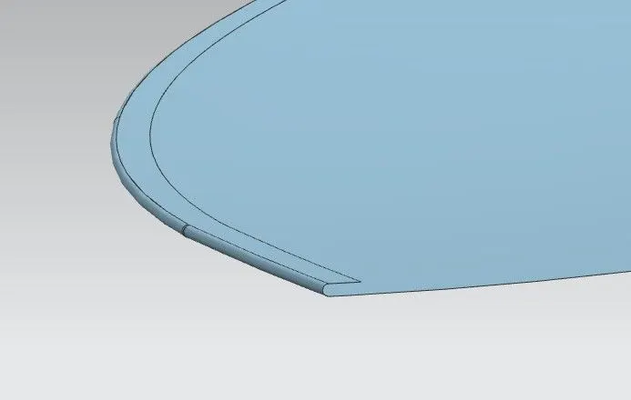
STEP 8 : Using curve on surface command, provide rear relief to flange of the outer panel.
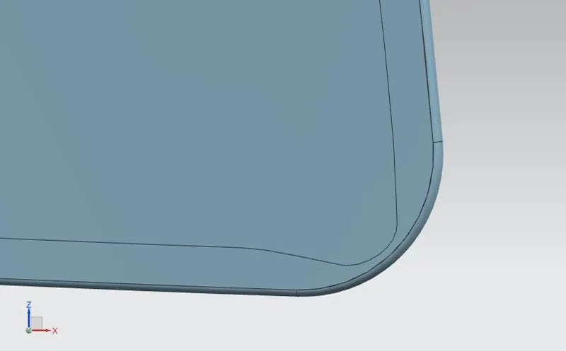
STEP 9 : Using curve on surface command, provide front relief to flange of the outer panel.
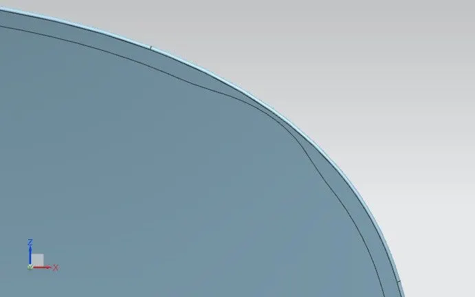
STEP 10 : Use Mirror Geometry to reflect the half portion of the outer hood.
- After the mirror sew both halfs surfaces.
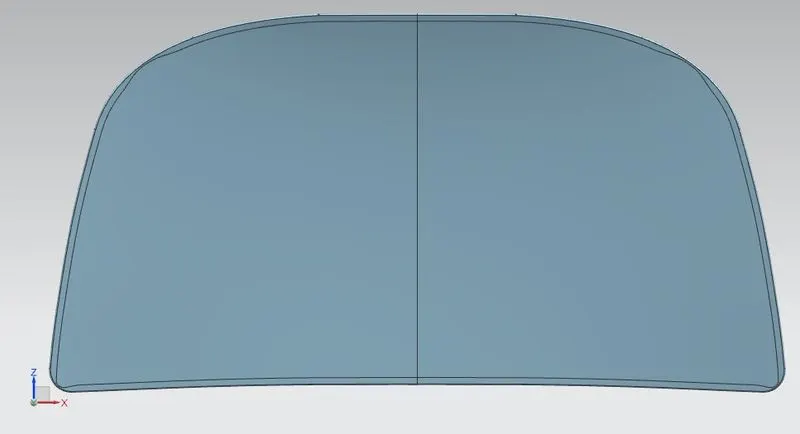
STEP 11 : Provide the thickness (thicken of 0.75 mm) to the entire outer panel sheet.
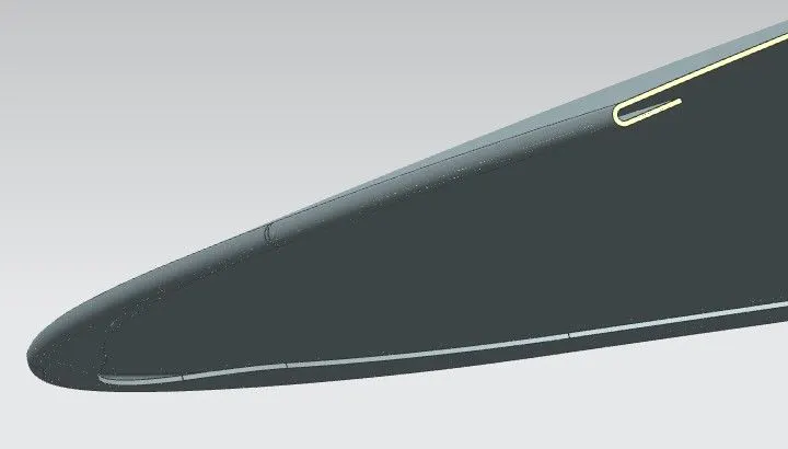
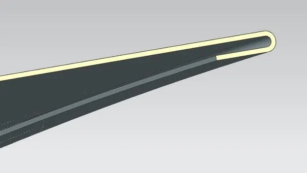
DESIGN OF INNER PANEL OF THE HOOD :
STEP 1 : Trim the Working surface into half by trim body command through Y axis or YZ Plane.
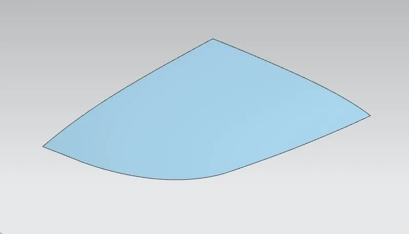
STEP 2 : Offset the working surface to 1.7mm downward direction.
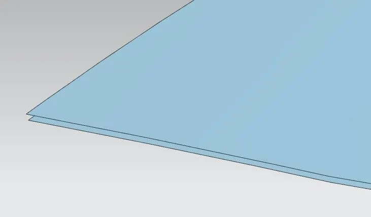
STEP 3 : Using offset curve in the face to 10mm and trim the sheet as shown.
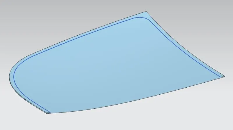
STEP 4 : Offset the working surface to 4mm downwards.
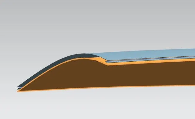
STEP 5 : Using offset curve in the face to 40 mm.
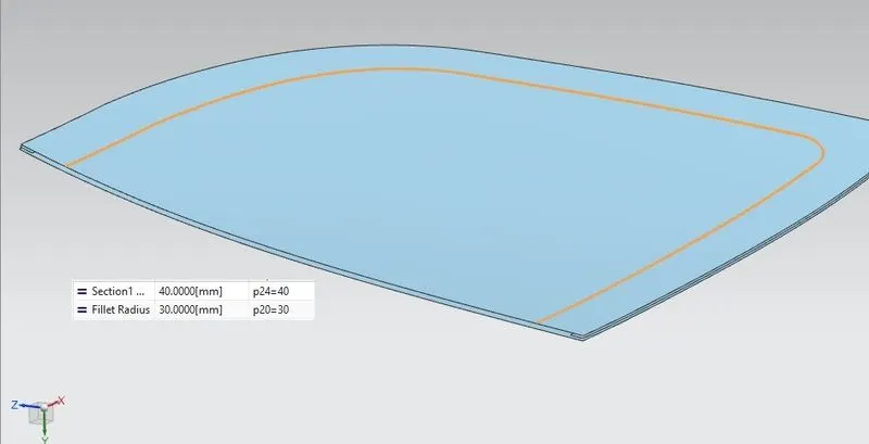
STEP 6 : Trim the sheet with the curve.
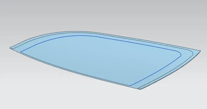
STEP 7 : Using through curves connect both the sheets.
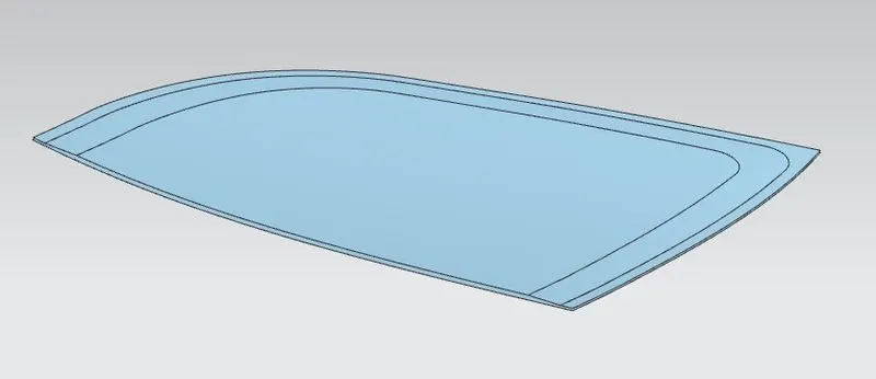
STEP 8 : Offset the working surface to 25 mm downward direction.
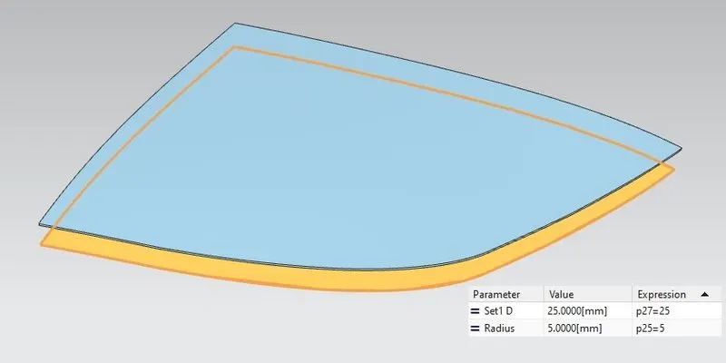
STEP 9 : Using offset curve in the face to 55 mm and trim the sheet as shown.
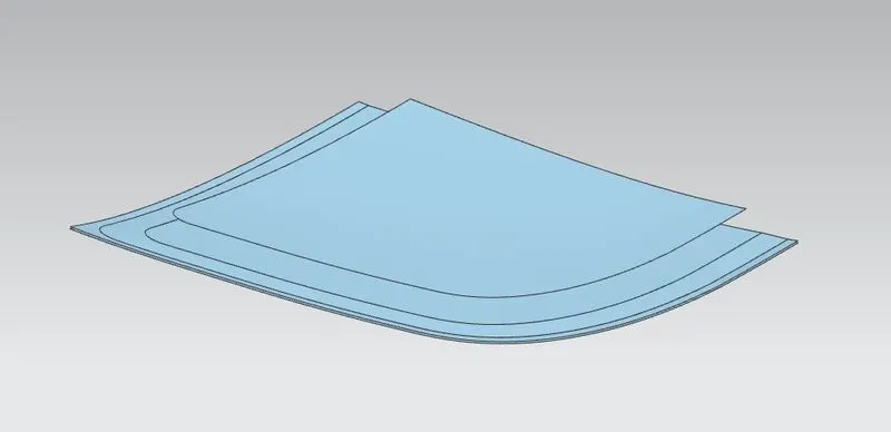
STEP 10 : Using law extension extrude the edge by 30 mm and 80 degrees of angel as draft.
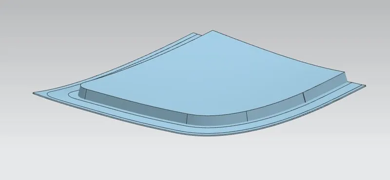
STEP 11 : Perform trim and extend on both the sheets.
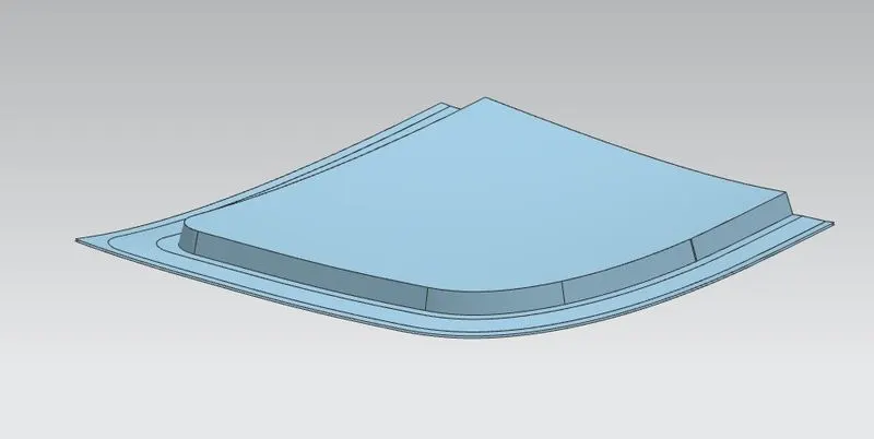
STEP 12 : Perform face blend or edge blend as per provided master section of hood.
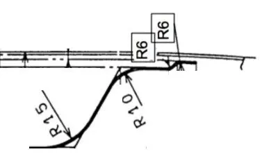
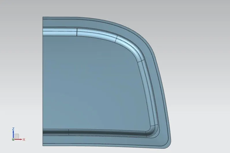
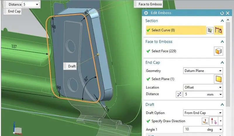
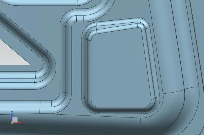
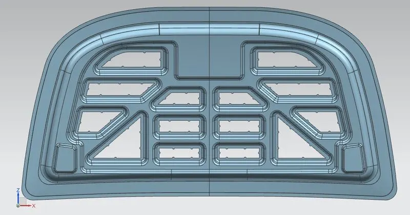
STEP 13 : Sketch, Project and Emboss with 5 mm depth and 10 degrees of draft towards working surface and tooling direction to X axis, leaving the area of hinge and striker as shown.
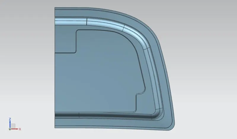
STEP 14 : Sketch, Project and Emboss with 13.5 mm depth and 10 degrees of draft towards working surface and tooling direction to X axis.
- Emboss are the projections made on sheet metal using deep drawing techniques. The function of embossing is to dissipate the force acting on the hood during the collision of the car toward the hinges as possible. this helps to reduce the impact of the force on the passenger sitting inside.
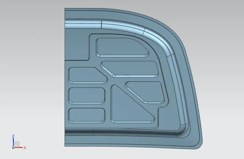
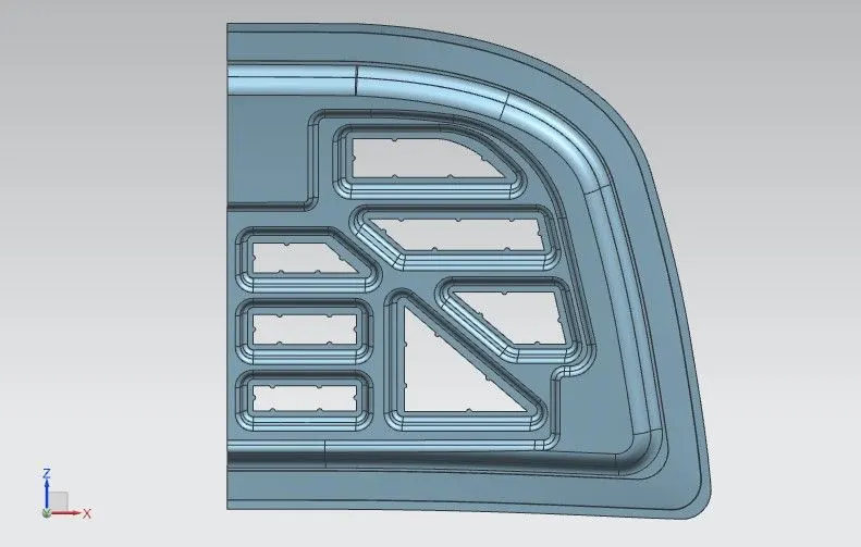
STEP 15 : Sketch, Project, Trim and give edge blend to the inner panel as shown in the picture which has Mastic points in the sheet. Sheet is cut out to reduce the weight of the inner panel.
Mastic sealant : The Mastic sealant or mastic point is an elastic compound that behaves as an adhesive and sealant, it is applied between Hood's outer panel and inner panel. It has a diameter area of about 80mm once it gets steaks between the panels.
PROCEDURE TO CREATE HINGE EMBOSS
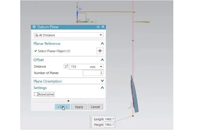
STEP 16: Creating Datum Plane, We should have a Datum coordinate system in the inner panel part.
*Home>Datum CSYS>DAtum Plane>At Distance>Select XZ Plane>Drage the handle near to the inner panel>Untick Associative checkbox.
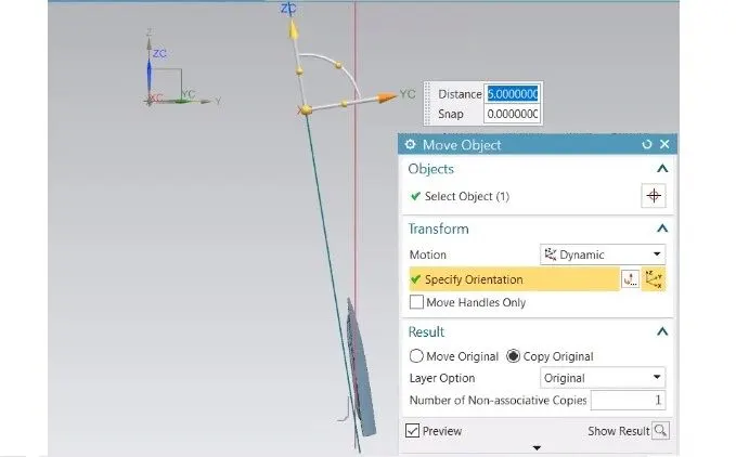
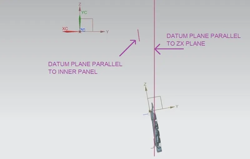
STEP 17: We’ll Create hinge emboss parallel to the inner panel.
*Tools>Move Object>Select new plane>Dynamic>Move, drag, set angle to the handle so that plane should be parallel to the inner panel.
STEP 18: Sketch the hinge and provide emboss and give edge blend as shown
STEP 19 : Use Mirror Geometry to reflect the half portion of the inner hood.
- After the mirror sew both halfs surfaces.
PROVIDING CONSTRAINTS TO THE COMPONENTS
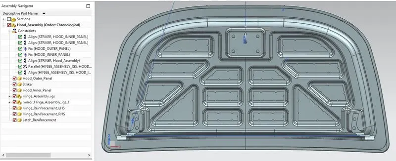
- Fix constrain the outer and inner panel.
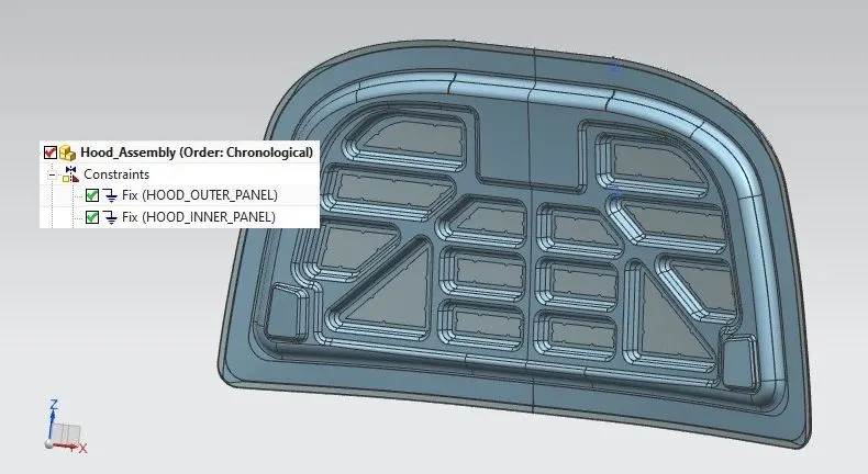
- Parallel Constrain to Hinge assembly central axis and X axis of datum coordinate system.
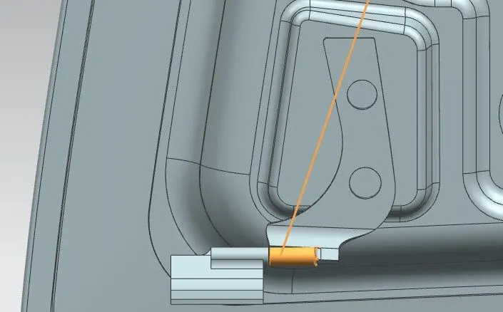
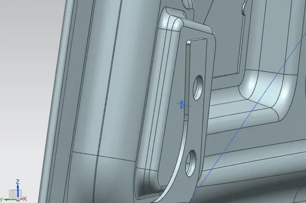
- Align constraint to Hinge assembly flat surface and Hinge Emboss surface if inner panel.
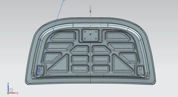
- Use mirror assembly to reflect the hinge assembly and its constraints by giving associative property.
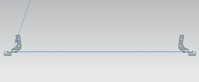
CREATING CENTERLINE FROM HINGE AXIS ON HINGE ASSEMBLY PART
- Create a Point from arc/circle definition on one hinge.
- Create a Point from arc/circle definition on another hinge.
- Use point to point line definition to create a Line, this line will be parallel to X axis of main coordinate system
CREATING TRAJECTORY OF THE STRIKER ON INNER PANEL PART
- Sketch a Circle in YZ plane, its center must lie on the center of the line we make in the hinge assembly above.
- Create a tangent line to the circle as shown.
- Constrain the Circle and Provide Diameter and angel to the tangent line with reference to the horizontal line.
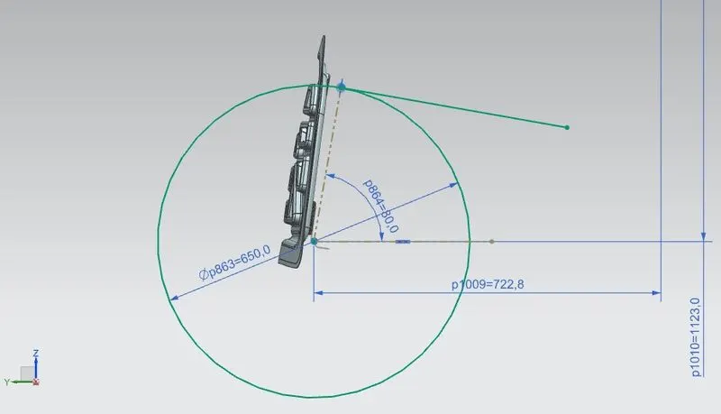
CREATING CENTERLINE FROM HOOK OF THE STRIKER
- Move and Drag the striker body near to its respective place of the inner panel.
- Create a datum coordinate system as shown in the picture below.
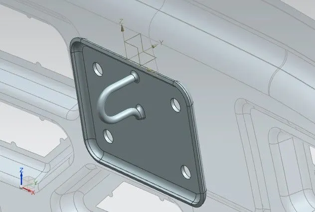
- Sketch a Line in YZ plane to that new datum plane of the striker,line should be in between hook of the striker.
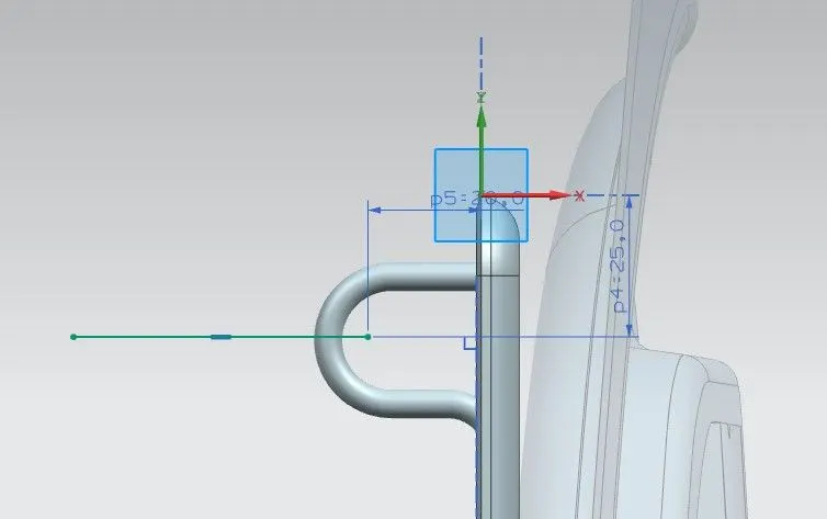
- Align end point of the striker line with the tangent line point of the inner panel circle.
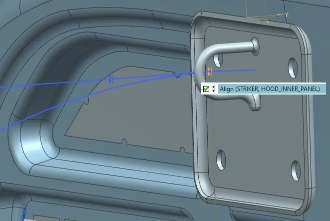
- Align front point striker line on the tangent line of the inner panel circle.
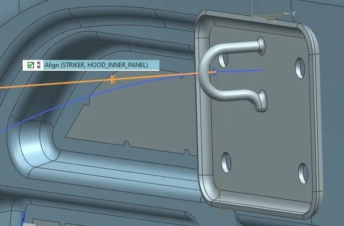
- Align YZ plane of the striker coordinate system to the main YZ plane of Datum coordinate system of the hood assembly.
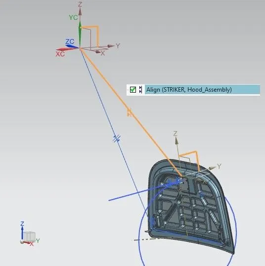
PROCEDURE TO CREATE STRIKER’S EMBOSS ON INNER PANEL
STEP 1 : Make the inner panel work part current, and use Wave Geometry Linker and extract the resting face of the striker.
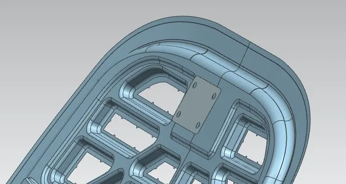
STEP 2 : Extend the Edge of the sheet by a few millimeters and use a law extension with length 35 mm and draft angle of 10 degrees towards the working surface of the inner panel.
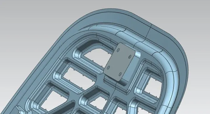
STEP 3 :Sew the extended sheet with Law extended sheet.
STEP 4 : Use trim and extend to get an emboss for striker.
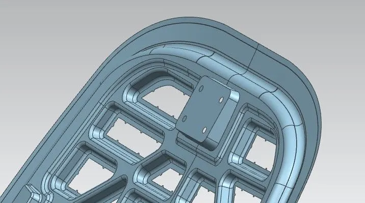
STEP 5 : Provide Edge blend of 5 mm.
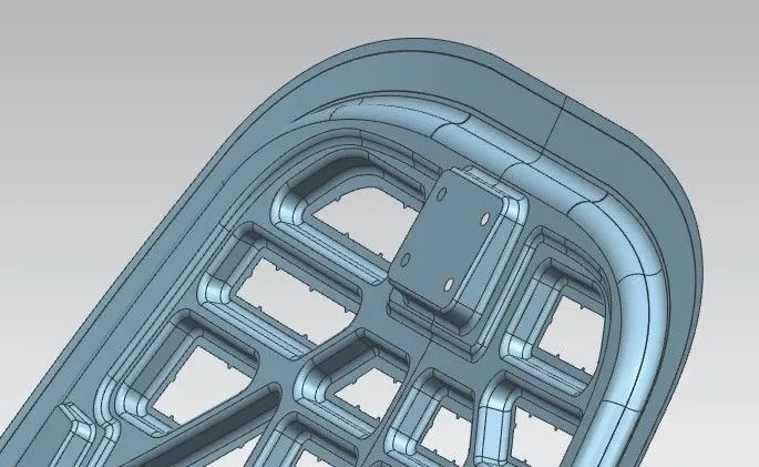
STEP 6 : Provide thickness of 0.75 mm to Final Inner Panel Sheet.
CREATING HOLES ON HINGE EMBOSS OF INNER PANEL TO FIX HINGE ASSEMBLY
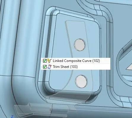
STEP 1 : Make the inner panel work part current, and use Wave Geometry Linker and extract the edge of the holes on hinge assembly.
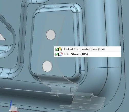
STEP 2 : Trim the sheet.
STEP 3 : Again follow above steps to perform the same operation on opposite side of the hinge emboss.
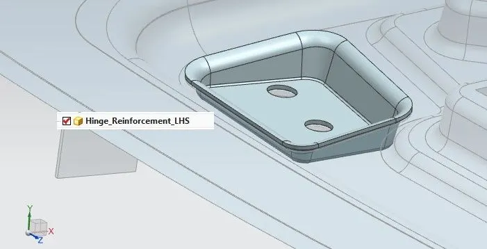
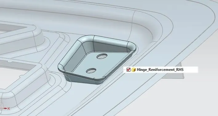
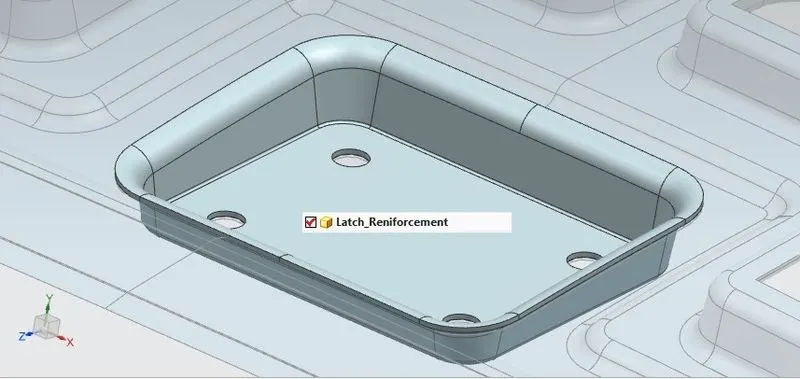
PROVIDING REINFORCEMENT TO LATCH AND BOTH HINGE EMBOSS
- Make the inner panel work part current, and use Wave Geometry Linker to extract the faces inside the latch and both hinges emboss one by one.
- Provide thickness of 1.5 mm to those surfaces.
NOTE : Wave Geometry Linker should be used to extract face only after providing thickness to the inner panel, otherwise thickness of reniforcement will overlap/intersect with thickness of inner panel.
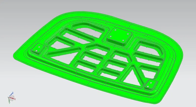
DRAFT ANALYSIS
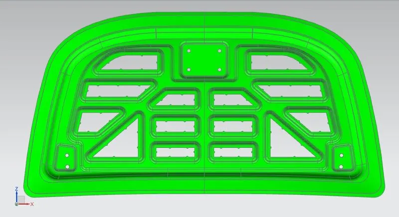
*Toolbar>Menu>Analysis>shape>Draft Analysis>Select Vector>Select Body
RESULTS
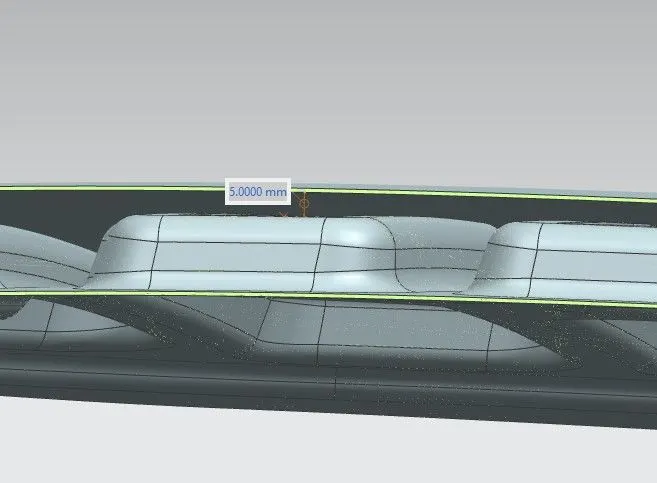
- Distance between outer and inner panel embosses is 5 mm, which will be filled with mastic point adhesives.
- Distance between Hemming flanges of the outer panel and inner panel is 0.2 mm from both sides.
- Constraints, Hood Assembly and Final Hood Model Tree.
__END__