Hood design-Week 2
Aim:
-
To design and develop a Hood Assembly (Hood Inner Panel, Hood Outer Panel, Reinforcements for Striker and Hinges) from the given skin data, master section and design parameters .
-
To explain the terminology involved in the design process of a Hood.
-
To explain the manufacturing processes employed in the creation of a Hood.
Abstract:
The project report deals with the explanation of steps and procedure followed while developing the HOOD Assembly of a car using CATIA V5. Using the styling surface and master section as input, we were able to create a HOOD outer panel and inner panel with features like embossments and mastic points. After creating the HOOD outer & inner panels, I have created a complete HOOD assembly consisting of the outer panel, inner panel, latch, hinge & reinforcements. In the end, a Draft Analysis has also been performed using the main tooling axis to check the manufacturability of the components.
HOOD:
The hood or bonnet is the hinged cover over the engine of motor vehicles. Hoods can open to allow access to the engine compartment or trunk on rear-engine and some mid-engine vehicles for maintenance and repair. It generally covers the engine and other essential accessories like battery, Radiator, electrical components, etc. of the car which are exposed outside. The Hood consists of an outer panel and an inner panel. The inner panel provides strength and support, where the outer panel is a metal cover that has styling factors. While designing the hood, a design engineer needs to make sure that the following design requirements are followed.
-
Pedestrian safety
-
Occupant safety
-
Vehicle quality
-
Styling
-
Ability to manufacture
Out of these requirements, Pedestrian safety & Occupant safety are the most important factors. Euro NCAP is a voluntary vehicle safety rating system that will provide European consumers with information regarding the safety of passenger vehicles. The more stars, the better safety it will be provided to the customer. Thus a design engineer must need to follow these requirements to provide better safety to the customers.
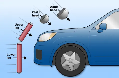
Vehicle designers usually focus on understanding the car-pedestrian interaction, which is characterized by the following sequence of events: the vehicle bumper first contacts the lower limbs of the pedestrian, the leading edge of the hood hits the upper thigh or pelvis, and the head and upper torso are struck by the top surface of the hood and/or windshield. Most pedestrian deaths occur due to the traumatic brain injury resulting from the hard impact of the head against the stiff hood or windshield. In addition, although usually non-fatal, injuries to the lower limb (usually to the knee joint and long bones) are the most common cause of disabilities. The hood
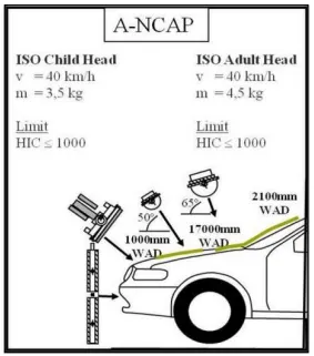
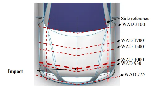
of most vehicles is usually fabricated from sheet metal, which is a compliant energy-absorbing structure that poses a comparatively small threat. Most serious head injuries occur when there is insufficient clearance between the hood and the stiff underlying engine components. A gap of approximately 10 cm is usually enough to allow the pedestrian’s head to have a controlled deceleration and a significantly reduced risk of death. Most limb injuries occur due to a direct blow from the bumper and the leading edge of the hood. Wrap Around Distance (WAD) is the distance from the ground level to the end of the hood as shown in the image.
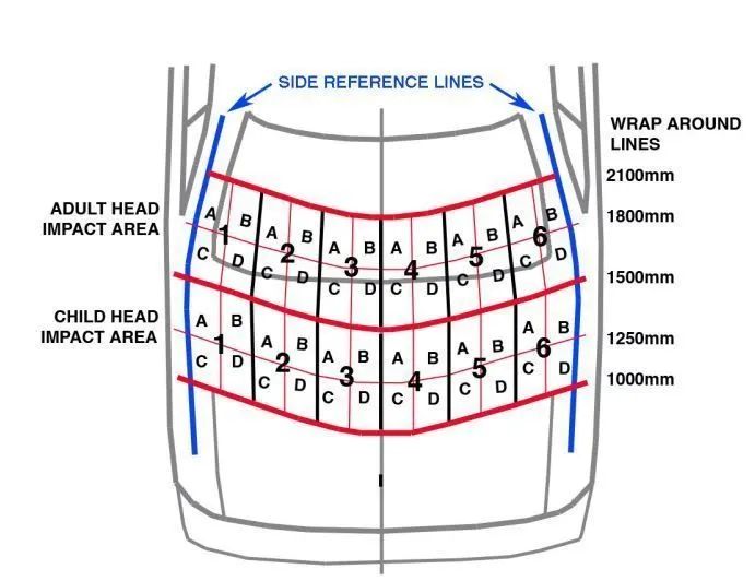
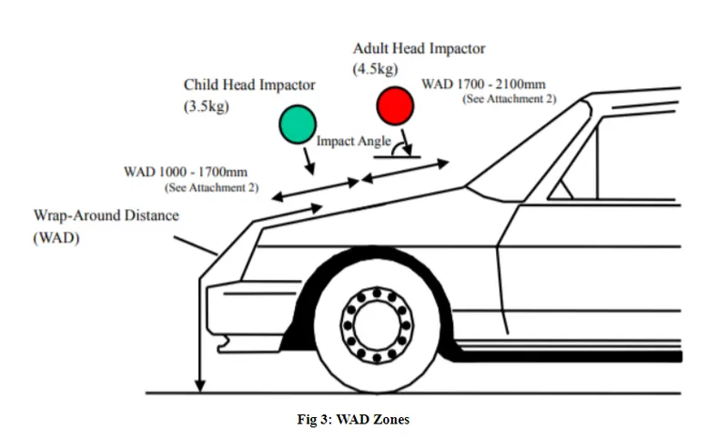
There are two main zones that are considered while the designing stage; the Child head impact zone (1000mm to 1700mm WAD) and the Adult head impact zone. (1700mm to 2100mm WAD). If the side reference line is on the fender, the WAD will be more and the impact zone will be less and vice versa.
Tool used: CATIA
Design Requirements:
-
Skin data.
-
Master sketch.
-
Hemming data.
-
Hood thickness information.
-
Hinge And Latches.
Design considerations :-
-
The human comfort factor for automobile design is first consideration. It is a method to safeguard and protect space for the human user and necessary components that make up the vehicle being designed.
-
All safety regulations are ensured during this process. Ergonomic considerations consist of Hood clearance, Hood Opening angle and location of support rod or gas stay.
-
Opening Angle Consideration : This is one of the main criteria in designing the hood . This opening angle varies from person to person and country to country . For example the average height of Indians is 5.8 whereas in European countries the average height will be 6 feet, based on these heights the opening angle may varies.The opening angle is considered important criteria because when the opening angle is less there is a chance of head injury to the human.
-
Safety requirements :- The most important safety requirement is regarding the frontal collision.It should withstand high collision forces as well as it should divert the forces in outward direction so intensity of collision forces would be reduced to cabin side of car.
-
Pedestrian safety :-Design should be such that it should reduce the injuries to the pedestrians in the event of a pedestrian vehicle collision. The objective of these measures is to reduce the severity of injuries sustained by pedestrians involved in a collision with a vehicle in urban traffic. The height, weight and age of the pedestrian all play a role in the kinematics of the event and in his ability to survive. Most fatalities for the younger population are related to brain damage caused by head impact on the bonnet. For older people additional risks include rupture of arteries in the lower limbs and pelvis from bumper and bonnet leading edges.Impact frequency and seriousness of injury has been studied for many years, resulting in rating systems and improved design.
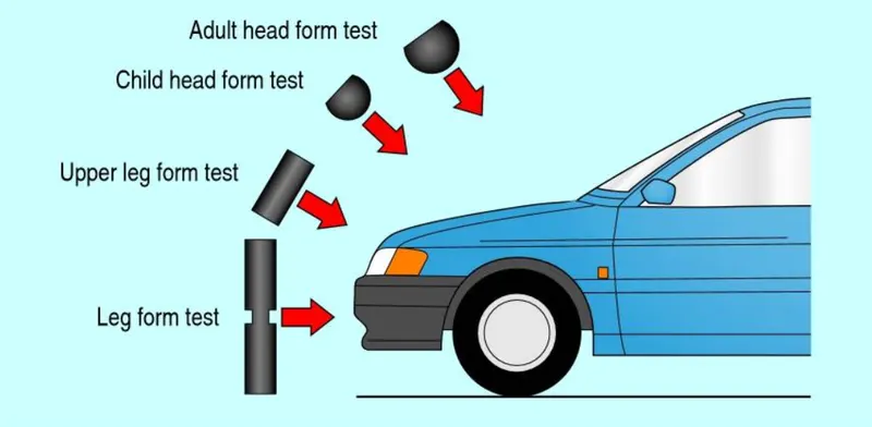
Padestrian safety NCAP (New car assessment program) standards:
Globally, various NCAPs are present that carry on the pedestrian safety tests on new vehicles and rate them accordingly.
1. Head Impact
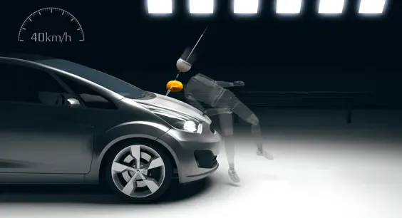
This test is carried out for a vehicle speed of 40 km/h. To have an estimate of the potential head injury in the fateful event of a vehicle striking an adult or a child, a head form impactor is used in a series of impact tests and the impact sites are then assessed for and rated accordingly.
This test will give essential information about the deformation clearance, energy-absorbing structures and deployable protection systems such as pop-up bonnets and external airbags in a new vehicle.
2. Upper Leg Impact
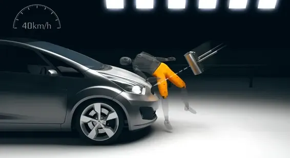
The facility carries out the test at the vehicle speed of 40 km/h. An adult upper leg form impactor is used in a series of impact tests and then the impact sites are assessed. The protection is then rated as good, adequate, marginal, weak or poor. The test procedure allows to check the energy-absorbing capacity of the structures of a vehicle and also check whether the geometry of the vehicle allows mitigation of injuries.
3. Lower Leg impact
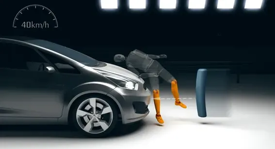
Euro NCAP carries the test at the same speed standard as the above ones. It uses an adult leg impactor and a series of tests are carried out. Impact sites are then assessed and the protection rating is offered.
4. AEB Pedestrian
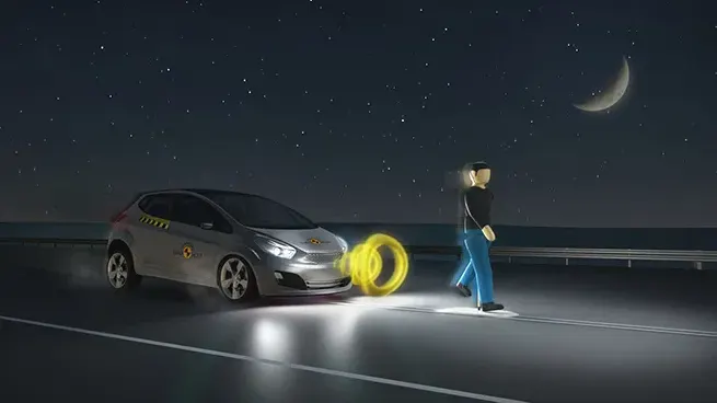
For this test, the NCAP uses a specially-designed pedestrian form which has articulated limbs to replicate the walking motion of a human. Cars are assessed on the basis of how forgiving the front-end design is in case of impact. AEB pedestrian tech may not be able to completely avoid a collision in some cases. The tests are done in the day as well as night to ensure vulnerable road users are protected all the time.
5. AEB Cyclist
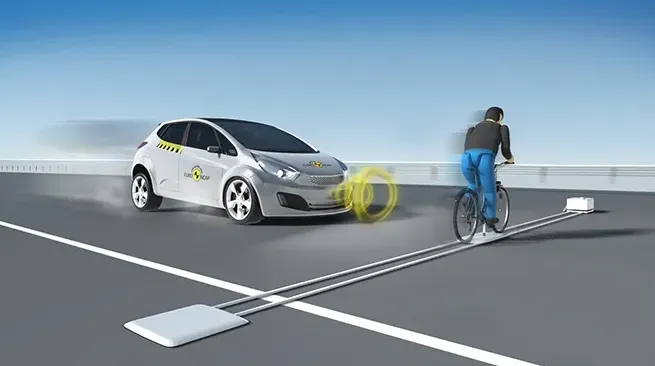
For this test, Euro NCAP uses a specially designed cyclist form which will replicate the actual cyclist on the road. Euro NCAP offers the highest rating if the collision is completely avoided. The vehicle is also awarded if the speed is reduced as any reduction in speed of impact can significantly reduce the injury to the vulnerable user.
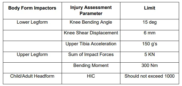
In order to measure the potential head and leg injuries in the front portion of the car illustration of crash mitigation tests is designed below:
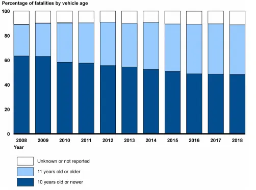
A research was performed which shows the percentage of pedestrian fatalities by the age of vehicle that struck the pedestrian fron 2008 to 2018 is shown below:
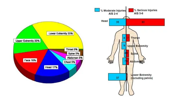
Approximately 1.2 million road traffic fatalities occur each year (The World Bank, 2002). The number of pedestrians surviving vehicle impacts with injuries far exceeds the number of fatalities.
The most common method of defining the injury severity in road accidents is Abbreviated Injury Scale (AIS) with a scale from 1 to 6 where 1 represents a minor injury, 2 moderate, 3 serious, 4 severe, 5 critical and 6 fatal injuries. Additionally, AIS 9 is used to indicate unknown status of injury severity. Distribution of AIS 2+ injuries from the Pedestrian Crash Data Study (PDCS) database in the U.S. shows that the frequency of injuries to the lower extremities and head dominates
Because injuries to the head often lead to death so head injuries are considered as the most serious injuries. Lower limb injuries are also important because they could lead to long-term impairments and result in high social costs.
The vehicle is marked by following the marking guidelines given by EuroNCAP (Euro NCAP Pedestrian Testing Protocol Version 5.2.1). The various marking lines used are bumper reference lines, bumper corners, hood leading edge reference line, hood
side reference lines and hood top WAD lines. 1,000-1,500 WAD lines mark as child head impact zone and 1,500-2,100 WAD lines mark as adult head impact zone. Head 45 impact speed of 40 km/h, child headform impact angle of 50o and adult headform impact angle of 65o is used.
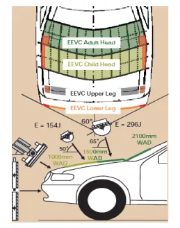
The above image shows the zoning of pedestrian head impact protection for NCAP
According to the requirements of the Australian New Car Assessment Program (ANCAP) for pedestrian protection, it needs to define zones of car hood for analysis, as shown in Figure 4. It can be noted that when the collision projection point locates between (Wrap Around Distance) WAD 1000 and WAD 1500, the head type will use the children head type. The adult head type will be used while the collision projection point locates between WAD 1700 and WAD 2100.
In 2012, EuroNCAP head injury assessment has been revised to be reported as overall performance score value (Euro NCAP Pedestrian Testing Protocol Version 6.0). Based on this new assessment criterion, Manufacturer must provide the head impact test data for all grid points tested and should be presented based on color scheme as:
Green HIC < 650>
Yellow 650 ≤ HIC < 1000>
Orange 1000 ≤ HIC < 1350>
Brown 1350 ≤ HIC < 1700>
Red 1700 ≤ HIC 0.00 point
A maximum of 24 points is available for head impact test zone. Total score of all grid points is calculated as percentage of maximum achievable score and then multiplied by 24. For e.g. if 190 grid points are tested which resulted into total points of 96. Then percentage achievable score is 96/190 = 50.5%, which multiplied by 24 gives 12.12 points.
From the above information we can conclude that pedestrian safety has become of the major factors while designing the hood and overall body of the car inorder to avoid accidents and deaths that happen on the roads.
NVH (Noice, Vibration and Harness)
Noise, Vibration and Harshness, and is basically a measure of how much unpleasant aural and tactile feedback the car delivers as you drive.
What does NVH actually mean?
The noise is what you can hear, the vibration is what you can feel and the harshness is how much of an effect thumps, bumps, noise and vibration have on the cabin and its occupants. Removing and isolating passengers from NVH is a field that's seen monumental advances over the past few decades. Originally the preserve of the most luxurious marques - and an acronym that was only even discussed by premium brands - NVH reduction is a global push, spurred on by consumers who want increasing insulation from the environment they're driving through.
What causes NVH?
Noise, vibration and harshness are caused by the car's mechanical and electrical systems, as well as the car's interaction with road surfaces and its passage through the air.
The main sources of NVH in a car are its engine, drivetrain and tyres, as well as the sound of airflow along its body.
Tyres are a huge source of noise, due to vibrations created by their rotation, which then travel along suspension mounts and into the cabin.
Low-profile tyres, found on sportier cars, tend to transmit more vibration through the suspension because the tighter, stiffer rubber can't absorb as much. Wide tyres are more susceptible due to a larger contact patch, but the soft, wide tread patterns of off-road tyres are the worst offenders.
Airflow over the car's body causes quite a bit of noise, especially at higher speeds and in large cars with the aerodynamic properties of a shipping container. Any interruptions the air faces in its journey across the car – such as aerials, roof racks and door mirrors – are rewarded with howling, whipping or buzzing noises in the cabin.
How to reduce NVH?
Cancelling out NVH comes down to three basic principles – reducing it at the source, isolating it from the car's main structure and absorbing as much as possible before it enters the cabin.
The first – if not the easiest – way to reduce NVH is to curb the number and volume of the sounds, vibrations and shocks produced in the first place.
The second and perhaps equally complex way to reduce NVH is to isolate the car's main structure from the source. Complex and expensive suspension tech such as independent, multi-link and hydro-pneumatic systems isolate the chassis and steering column from road surfaces, removing vibration and shocks.
To further isolate the sources of noise, engine, suspension and exhaust components are mounted on rubber and polyurethane bushes rather than solid metal; the softer compounds work against the transmission of vibrations.
The last resort in the war against NVH is also the most conventional: absorbing as much as possible. Mechanically speaking, this tends to refer to steering dampers, which absorb the worst of the shocks introduced by poor road surfaces.
The movement of the hood can be controlled by either one of them:
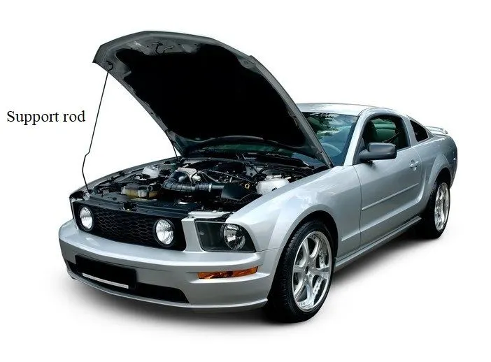
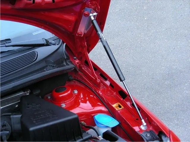
1) Support rod :- This is the most commonly used rod for opening and closing the hood at a certain angle. One end of the rod is hinged to the engine compartment and the other end is set free so that it can be locked to the hood inner panel when the hood is opened. This is usually used when the weight of the bonnet is small.
It is very important to consider that the support rod should not collide inside the engine compartment.
2) Gas stay :- It is a device used for supporting the engine hood of a vehicle in its open position by means of an actuator which is activated by gas.
In case of gas stay only initial force is required to open the hood then it automatically opens at desired angle with the extension of pneumatic piston in cylinder of gas stay assembly.
Advantages of Gas stay are as follows
-
No human effort is required
-
Easy to operate
Disadvantages of Gas stay are as follows
-
They are heavy in weight compared to the support rod.
-
Cost is more.
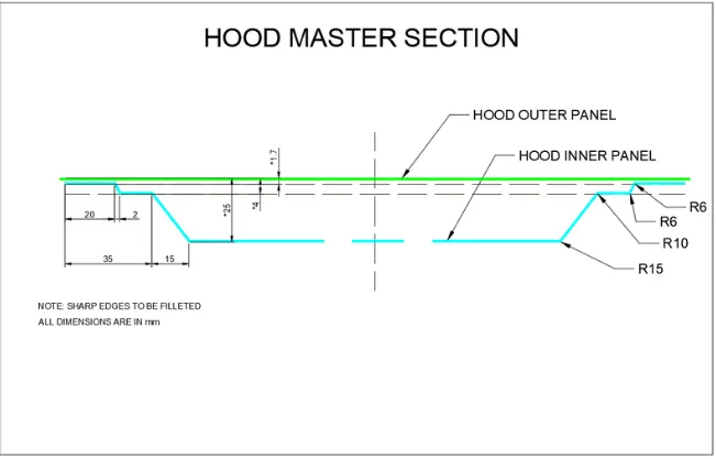
Master section:
This is the master section I have used in this project.
Hood Thickness Information
-
Outer Panel Thickness = 0.75mm
-
Inner Panel Thickness = 0.75mm
-
Reinforcement Thickness = 1.5mm
Procedure :
Creating Hood Inner Panel:
-
To create the Hood Inner Panel, the below input (i.e Master section) needs to be followed.
-
open the given model i.e, Hood styling surface in CATIA V5.Extract the surface and split it using the YZ plane to get the half portion of the surface.
-
Now following the master section, offset the surface (split surface) to 2mm.
-
After offsetting the surface, use the boundary option to create boundaries of the surface and then using the parallel curve option, offset the boundary on the surface for about 20mm (15+5mm).
Note: Since the distance from the corner to the first edge is not given in the master section, we are assuming a value of 15mm.
-
Now split this surface with the boundary which we offset to get the first inner portion surface of the Hood.
-
Similarly, we need to create all other inner portion surfaces for the Hood Inner Panel at different offset values by following the master section.
-
Offset the split surface (the main surface which we split with the YZ plane) to 4mm and again by extracting the boundary, offset it to 22mm (15+5+2mm) on the surface. Split the surface using this boundary and this will give us our second portion of the inner surface.
-
We also need to offset the boundary to 35mm (15+20mm) and split the second portion surface with it to get the inner edge of the surface.
-
Create a surface between the first and second inner portion surfaces (by selecting inner edges) using the Blend or Multi-Section option.
-
Now again offset the main split surface to 25mm and offset its boundary to 50mm (15+20+15mm) and split the surface. This will give us the third and final inner portion of the Hood Inner Panel.
-
Similarly, create a surface between the second and third inner portion surfaces (by selecting inner edges) using the Blend or Multi-Section option and give the required fillets to the edges by following the master section.
-
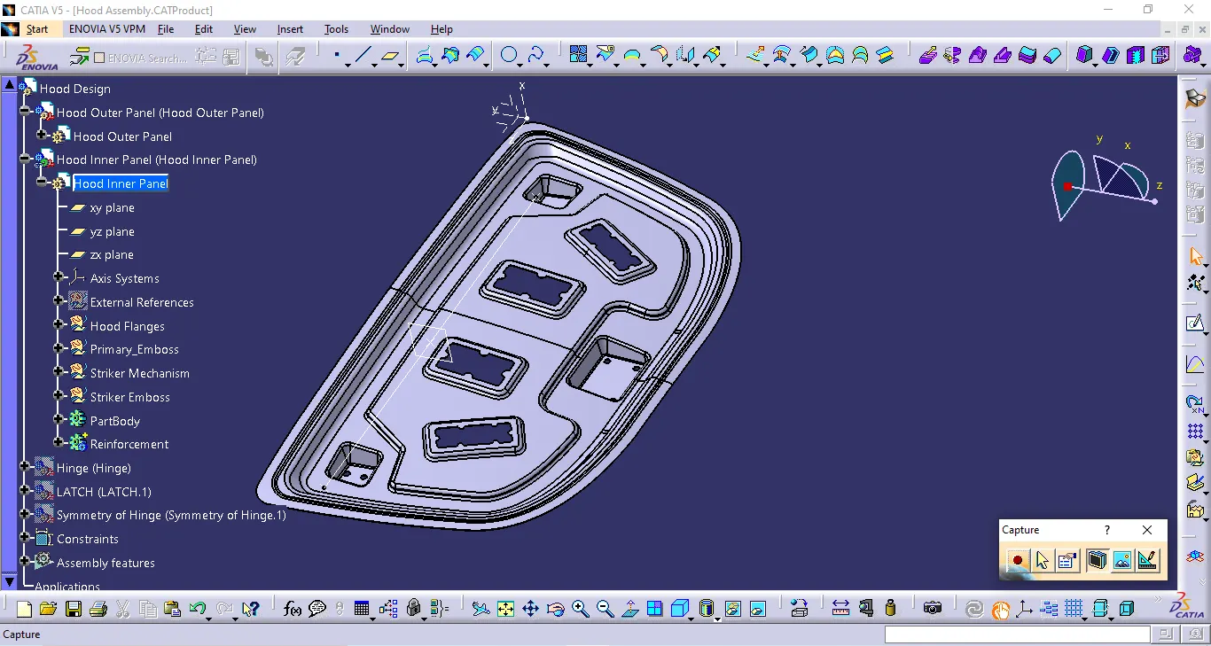
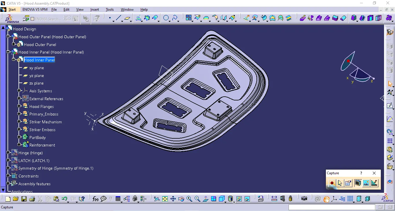
Now to create embossment, create a sketch (no specific dimensions is needed) and project this sketch on the Inner Panel surface.
-
Split the surface with this projected sketch to get the cut out for the embossment.
-
Using the boundaries of this cutout, sweep the surface with a draft value of more than 7 deg.
-
To create the base surface for the embossment, offset the main split surface with a value that can give the embossment a height of 5mm.
-
Now trim the sweep surface with the base surface of the embossment to get the final output.
-
Necessary cuts are needed for the embossments and they should be in such a way that the stress in the body that develops during an impact should not affect the occupant heavily.
-
After creating the embossments, mastic points are to be included near the hole regions such that these points are used to make sure that there is no gap between the outer and inner panels.
-
Now using the symmetry option creates a surface on the other side. Join these surfaces and if there is a gap between the surfaces, we need to create a surface in between them.
Note: A max of 0.003 merge value can be given while joining the surfaces.
Creating Hood Outer Panel:
-
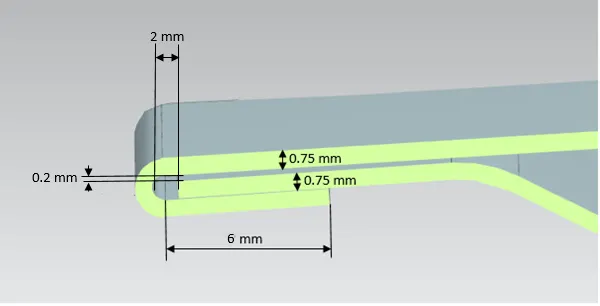
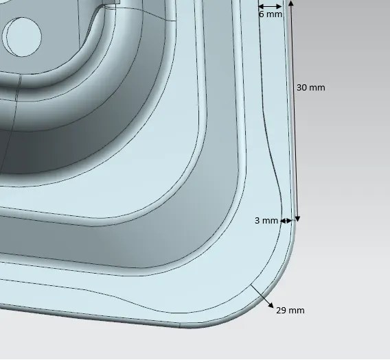
To create the Hood Outer Panel, the below inputs need to be followed.
-
Using the main split surface, create the outer panel by first extrapolating it to 2.75mm.
-
Now offset this extrapolated surface to 2.45mm and extract its boundaries.
-
Using the parallel curve option, offset the boundary to 6mm and split the surface using it.
-
Create a surface between the extrapolated surface and split surface using the Blend or Multi-Section option. Join the Surfaces and give an edge fillet to them.
-
According to the requirement, we need to give 3mm cutouts at the hemming regions.
-
Extract & offset the boundary to 3mm and using spline create the cutouts of 3mm.
-
Project these cutouts lines on the surface and split the surface using it.
-
Using the symmetry option creates a surface on the other side. Join these surfaces with a max merge value of 0.003mm.
-
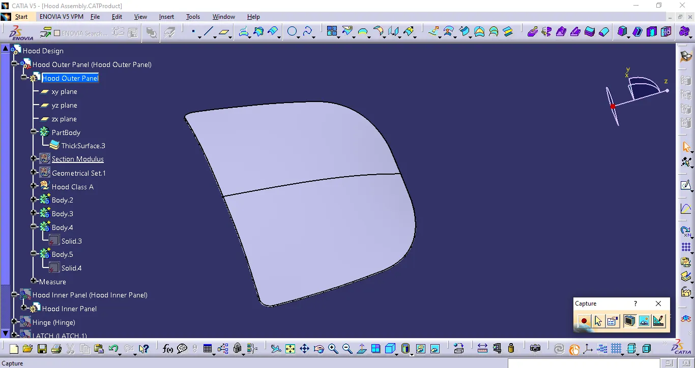
Create a solid body with a thickness of 0.75mm using the thicken option in the part workbench.
Creating embossment for Hinge:
-
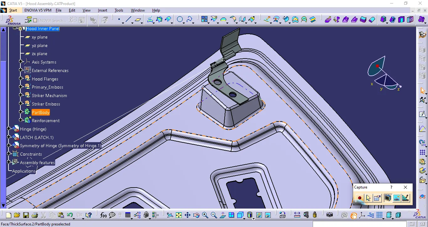
To create the embossment for Hinge, use the Assembly workbench to adjust the Hinge Part near the Hood Part using the manipulate tool.
-
Now, go to the Hood Model part workbench and create a sketch using the Hinge such that the embossment area can cover the hinge part.
-
Once the sketch is created, project it to the surface and split the surface using it.
-
Use the Sweep option to create the surface with a draft value of more than 7 deg.
-
Now extract the lower surface of the hinge part and extrapolate it. Trim the sweep and extrapolated surface to get the final output.
-
Mirror the Hinge Surface onto the other side and join these hinge with the main surface (Inner Panel).
-
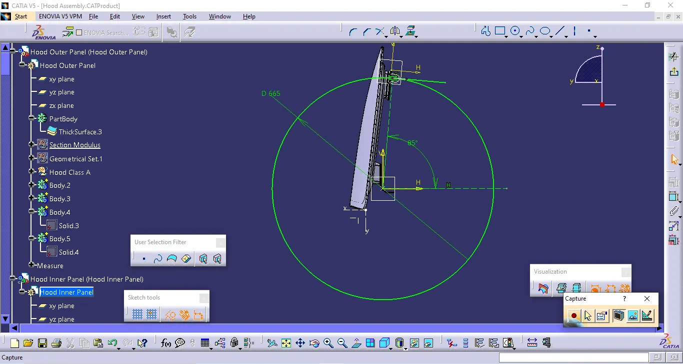
Create a point at the center of the Hinge circle at both ends and create a line using the two points.
-
Create the middle point using the two points created and create a circle using the middle point created. The circle trajectory should be tangent to the latch part.
Creating embossment for Latch:
-
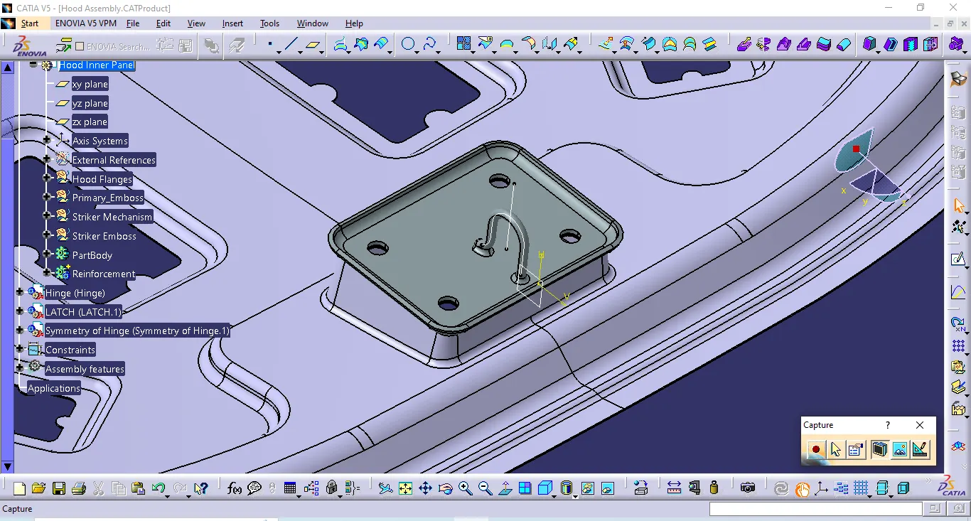
Creating embossment for Latch is similar to that of the hinge part but in this case, the latch part striker should be tangent to the circle.
-
Use the striker to create a sketch and project it to the surface and split it.
-
Now extract the lower surface of the striker part and extrapolate it.
-
Trim the sweep and extrapolated surface to get the final output.
-
Finally, join this surface with the Inner Panel Surface and thicken it in the part workbench with a thickness value of 0.75mm.
Creating Reinforcements:
-
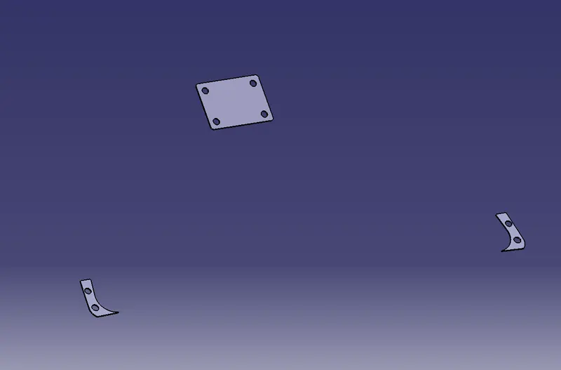
To create the Reinforcements, Go to the Assembly workbench, Click on the lower part of the Hinge and Latch surfaces and extract the surfaces.
-
Go to Part Workbench and Use the thick surface option to create a solid with a thickness of 1.5mm.
Four main parts of Hood assembly are as follows
-
Hinge
-
latch and striker system
-
Outer Panel
-
Inner Panel
Hinge: A hinge is a piece of metal, wood, or plastic that is used to join a door to its frame or to join two things together so that one of them can swing freely.
Latch: The hood latch helps to keep your hood closed. When the hood is closed, the latch slides over what is called a catch, and the spring covers the latch to keep it snug. When you pull the knob inside the car to open the hood, the hood latch cable opens the latch, allowing it to bypass the catch and open. There is, however, a second hood latch, to keep the hood from flying up if accidentally unlatched. That latch will need to be opened with your hand to get the hood fully open.
Latch Trajectory:Latch Trajectory is the orbital path in which the latch should be positioned to the lock hole. The trajectory is drawn based on the reference of the Hinge joint central axis.
Outer Panel: The Outer Panel is the most important part of the hood to make the car in a very good aesthetic proportion. So, the sheet metal operation result which is visible on the outer panel or it reduces the aesthetic value means those operations are strictly not to be followed to make the outer panel. That's why the hemming process is used to join the outer panel with the inner panel, instead of using welding methods.
Reinforcements: The purpose of reinforcement is to provide additional strength for the hood where it is needed. When the latch and striker are attached to the panel, the strength will be reduced in that area. To improve the strength in that area the reinforcement is added.
Mastic Data: Mastic is common as an adhesive and sealant. A mastic sealant is a type of liquid sealant that cures in an elastic state, thus making it flexible while holding the bond of the surfaces that have attached. It adheres to just about any material making an all-purpose type of sealant. Wood, aluminum, glass, marble, and even duct board are all standard applications for mastic sealant.
Hood has designed by the process of using the following Sheet Metal Operations:
-
Deep Drawing
-
Hemming
-
Blanking & Piercing
-
Embossing
The manufacturing process involves turning raw materials into finished products which are used for some purpose. The economics of the manufacturing operation is a very important consideration. To be viable in the modern environment, a product has to be competitively priced besides having functional and aesthetic appeal. There are different processes available for manufacture. These are classified as Casting Process, Forming Process, Fabrication Process, Material Removal Process.
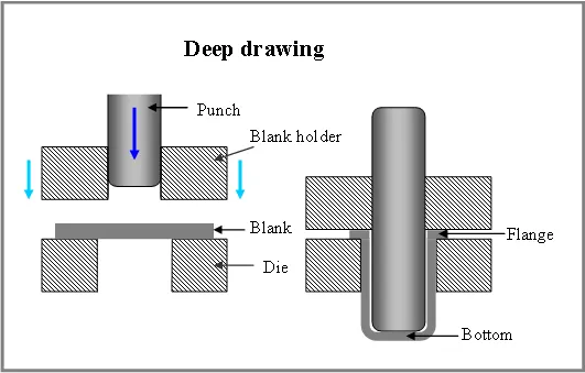
Deep Drawing: The deep drawing process is a forming process which occurs under a combination of tensile and compressive conditions. A flat sheet metal blank is formed into a hollow body open on one side or a hollow body is formed into a hollow body with a smaller cross-section
Deep drawing processes are divided into three types:
-
Deep drawing with tools
-
Deep drawing with active means
-
Deep drawing with active energy
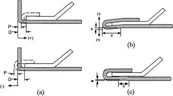
Hemming: Hemming is a sheet metal forming process in which sheets are joined by bending it usually to 180 degrees. Automotive body panels and automotive parts such as deck lids, trunk lids, doors, hoods, and tailgates are formed by the hemming process.
BLANKING AND PIERCING:
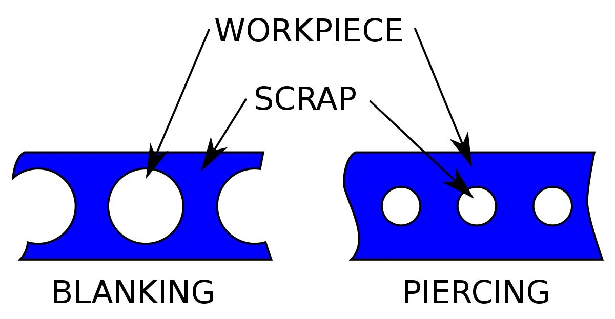
Piercing is a shearing process in which raw metal is pierced with a machining tool, resulting in the creation of a circular or other shaped hole. As the raw metal is pierced, the metal from the newly created hole is considered scrap. The piercing machine forces a tool, known as a blanking punch, through the sheet metal.
Blanking is often confused with piercing because both processes involve cutting holes into raw metal. However, they aren’t necessarily the same. With blanking, the metal from the hole is saved and used rather than discarded. In other words, manufacturing companies perform blanking to create small pieces of metal, whereas manufacturing companies perform piercing to create metal objects with a single hole.
Embossments:
Embossing is an operation used in making raised figures on the sheets, with corresponding relief on the other side. The process essentially involves drawing and bending the metal. The die set consists of a die and punch with the desired contours so that when the punch and die meet the clearance between them is the same as that of the sheet thickness. Embossing operation is generally used for providing dimples on sheets to increase their rigidity and for decorative sheet work used for panels in houses and religious places. Stretch forming operation is a relatively less severe operation.
Assembling the components:
-
To assemble the components, Go to the Assembly Workbench and constraint the parts using offset constraints. Give an offset value of '0' by selecting the embossment surface of the hinge and the lower part of the hinge. A similar operation needs to be performed for constraining the Latch.
-
Create an axis at the center of the holes of the latch and hinge embossment and their parts and coincide these axes with their respective parts.
-
Use explode & update option to check if all the parts are assembled properly or not.
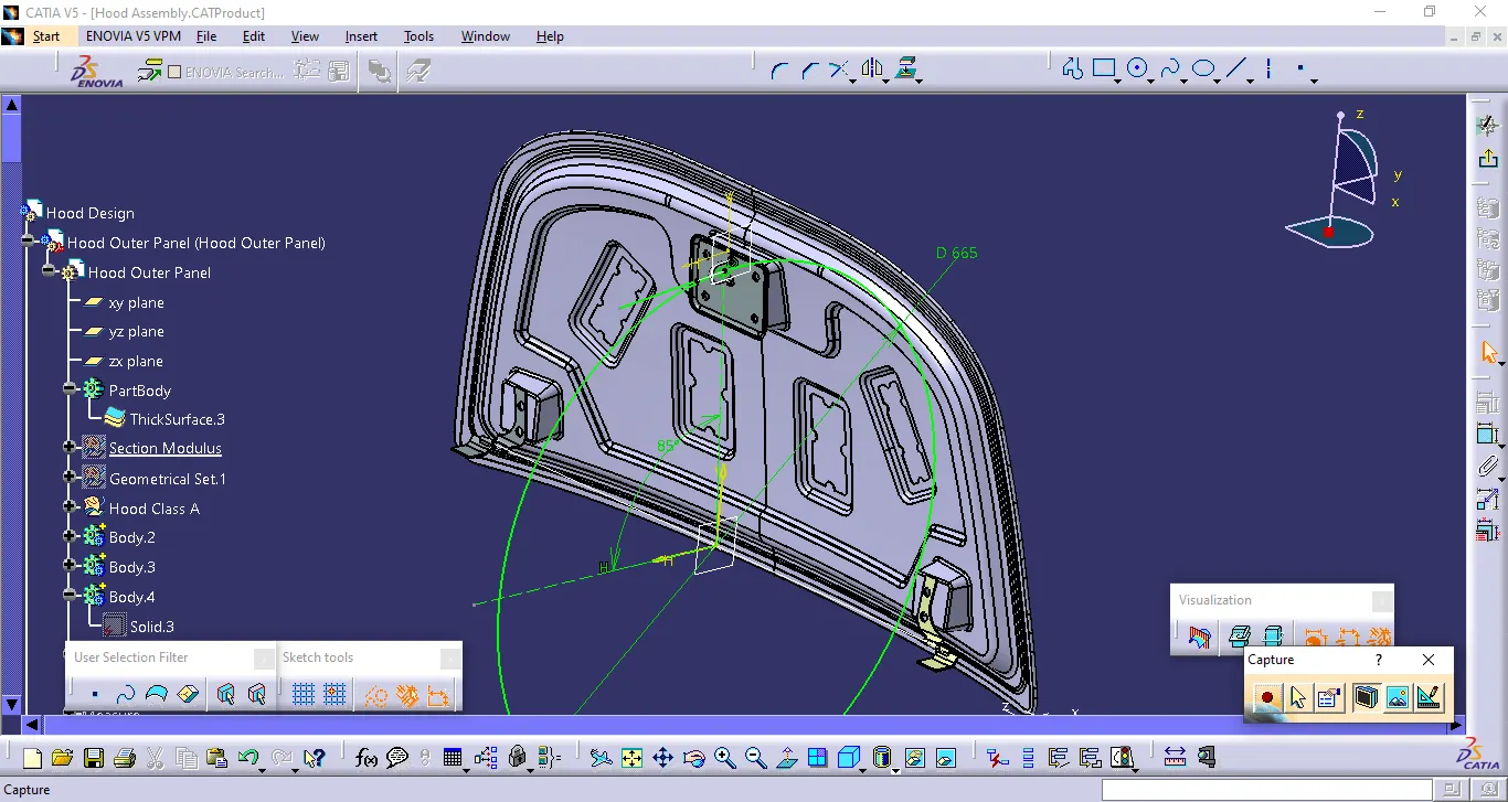
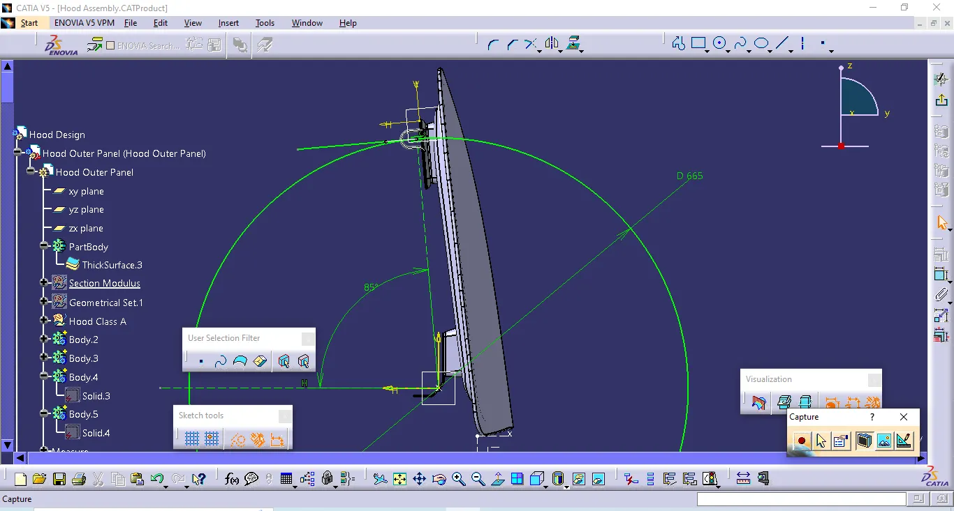
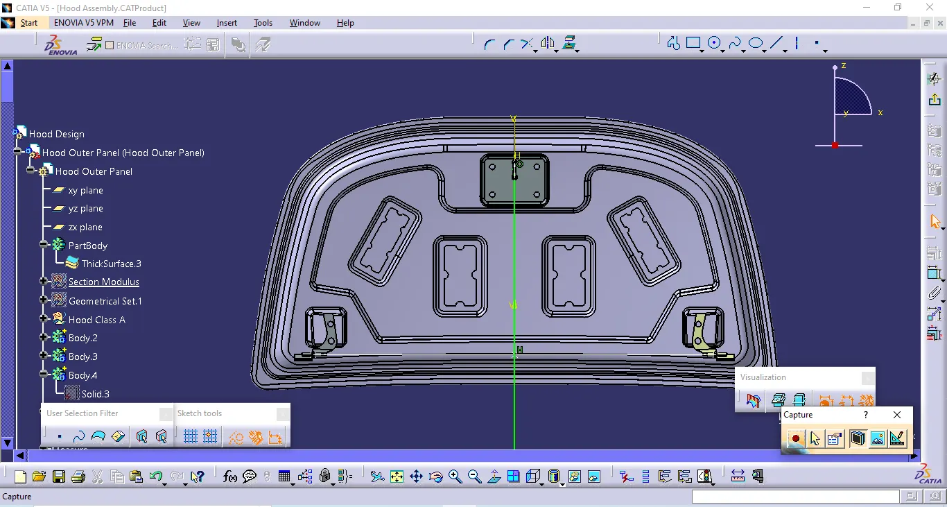
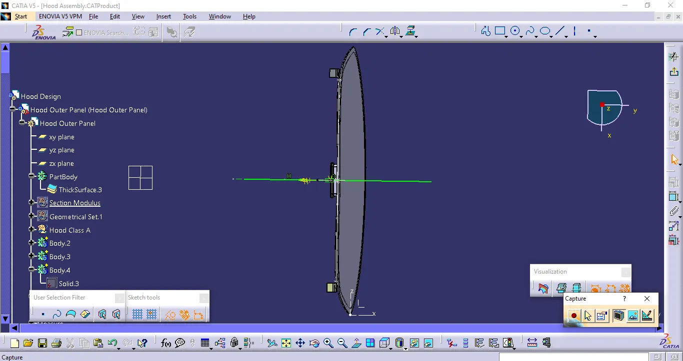
Note: attaching of the tree structure is not required, since it is visible in the above attached images
FINAL CAD MODEL:
Result: The design and development of the Hood inner panel, outer panel, latch, hinge and reinforcements is completed following the design parameters and also successfully assembled.