Hood design-Week 2
DESIGN OF CAR HOOD USING SIEMENS NX-CAD
OBJECTIVE
To design a car hood with inner and outer panel by placing Striker, Hinge and its reinforcement using SIEMENS NX-CAD.
INTRODUCTION
HOOD
The hood or bonnet is the hinged cover over the engine of cars. Hoods can open to allow access to the engine compartment on rear-engine for maintenance and repair. It is hinged thin sheet which covers and protects the main parts of car like engine. Its main function is to direct access to the engine, battery and other crucial parts of the cars for repair and maintenance and to protect these parts from direct sunlight and dust. It consists of Support rods or gas stays to hold the hood while it is opened. A hood may contain a hood ornament, hood scoop, power bulge and wiper jets etc.
BODY IN WHITE
It is the stage in automobile manufacturing in which a car body's frame has been joined together, that is before painting and before the motor, chassis sub-assemblies have been integrated into the structure. It helps to ensure that the welding process meets the pre-defined standards of high-quality. They provide the necessary support and stability to avoid distortions in the welding process, which can often lead to expensive iterations.
PARTS OF HOOD
- Outer panel
- Inner panel
- Striker
- Hinge Assembly
FUNCTIONS OF HOOD
- It helps to design car aerodynamically stable.
- Sometimes it is required to supply pure air so filter is provided on the bonnet to supply filtered inlet air.
- Hoods are provided with different vent designs for cooling purpose of an engine and carburettor at high speed.
- Scoops on hood having another function of supply of air for supercharger in case of supercharged engines.
- The function of hood is to handle this type of heavy engines with supercharger outside
- And lastly it also gives good looks
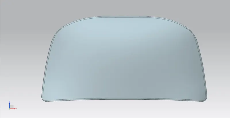
OUTERPANEL
The Outer panel of the Hood is a styling part which is attached to the inner panel which give strength to it using the mastic sealant and hemming.
INNERPANNEL
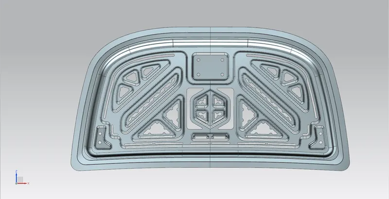
The inner panel of the hood is not visible to the customer but this is the engineering feature of the outer panel. The outer panel has the aesthetic look to it but on its own is very weak and not capable of handling force during impact. This puts the passenger’s life in danger, so we need to design the inner panel so as to provide strength to the outer panel.
MASTIC SEALANT
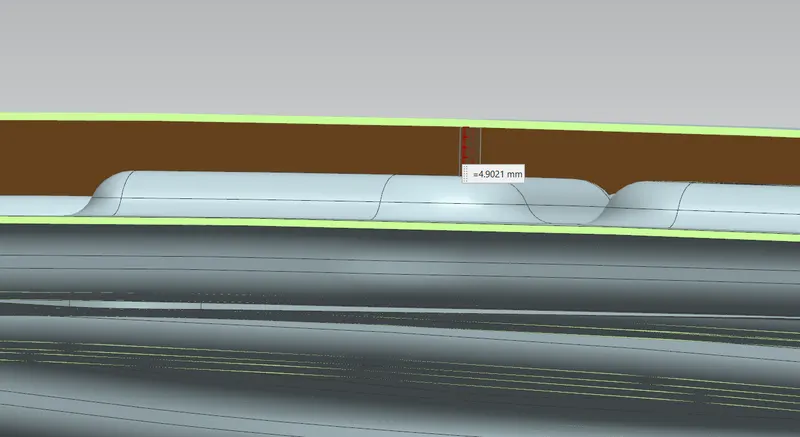
It is an elastic compound that behaves like a rubber. These points are defined on the hood inner panel where hood easily can deform. It helps hood outer panel to come back to its original shape after getting deformed. It also helps the inner panel fixed with the outer panel. The main function of mastic point is to reduce NVH (Noise, Vibration and Harshness) that created on hood. So, by providing more in number of mastic points at centre area of hood will increase the performance of car. It has capability to reduce the NVH for the radius of 80mm.
HINGES
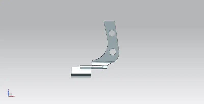
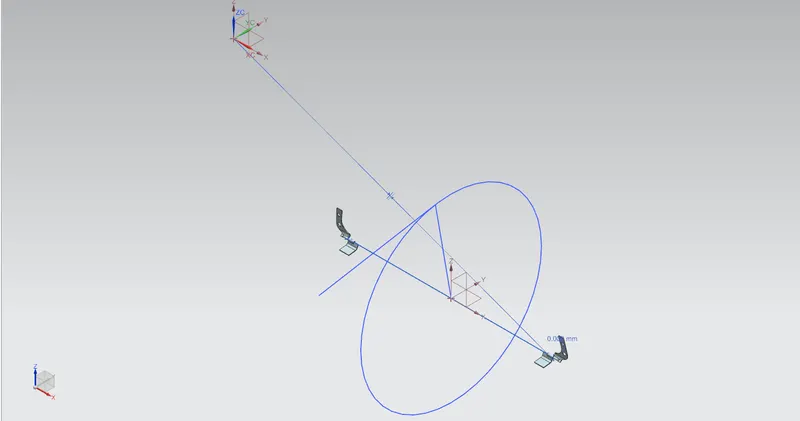
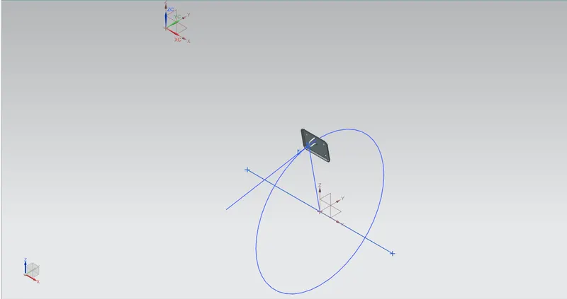
Hinges are used to connect the hood and cowl panel of an automobile. It enables the hood to swing open and close. Normally hinges are positioned in a way that the striker fits into hole provided. The line joining the midpoint of the hinge axis and tip of the striker should always normal to circular trajectory of the hood which rotates about the hinges. In simple words the line joining the midpoint of axis and tip of the striker should be always perpendicular to tangent of circular trajectory of hood of the tip of the striker. Hinge reinforcements are used to provide more strength to assembly.
STRIKER
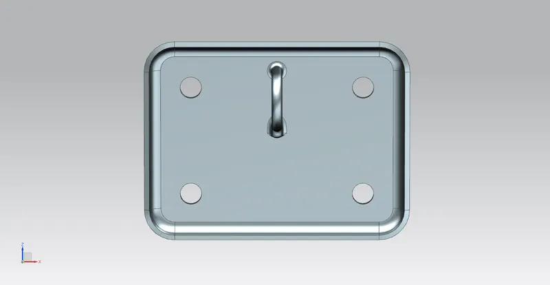
It is used to locking the hood with the car body. In this striker exactly fits into hole provided in the car body. The Latch & striker is fixed on hood inner panel using some fasteners and Reinforcements.
DESIGN METHODOLOGY
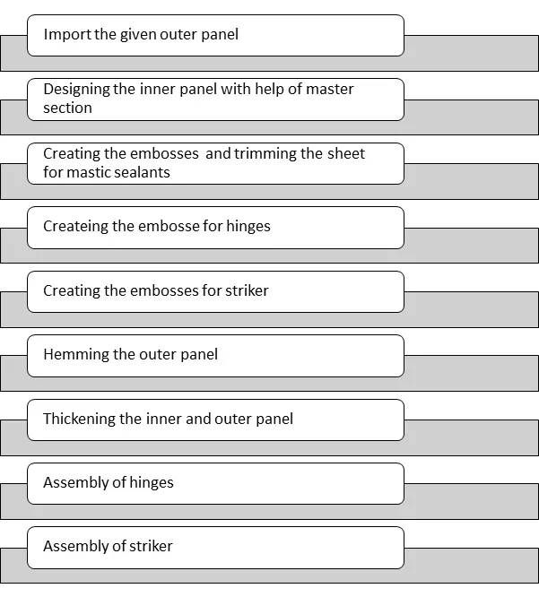
The design methodology of the Hood is explained with the help of flow chart for easy and better understanding
FLOWCHART
DESCRIPTION
There are various tools used to design the Metal Bracket II in the sheet metal application in SIEMENS NXCAD they are described as follows,
Features Used
Extract Geometry: Creates associative copies of bodies, faces, curves. Points, and datums and associative mirrored copies of bodies, within the same part.
Extend Sheet: Extends a sheet body by distance or to the intersection with another body.
Offset Curve in Face: Offsets curves along the faces on which they lie.
Law Extension: Creates a law -controlled extension from a base sheet, dynamically or based on laws for distances and angle.
Offset Surface: Creates a body by offsetting a set of faces.
Trim Sheet: Trims off a portion of a sheet body.
Face Blend: Adds Tangent bend faces between selected sets of faces. The blend shape can be circular, conic, or law controlled.
Edge Blend: Rounds sharp edges between faces. The radius can be constant variable.
Curve on face: Creates a surface spline feature directly on a face.
Thicken: Creates a solid body by adding thickness to a set of faces.
Trim Body: Trims off a portion of a body.
Through Curves: Creates a body through multiple sections where the shape changes to pass through each section.
Trim and Extend: Trims or extends a set of edges or faces to the intersection with another set of edges or faces.
Project Curve: Projects curves, edges, or points onto faces or planes.
Emboss: Modifies a body with faces made by projecting a section along a vector, with options for end cap location and shape.
Datum Plane: Creates a datum plane used to construct other features.
Datum CSYS: Creates a datum coordinate system used to construct other features.
Wave Geometry Linker: Copies geometry from other parts in the assembly into the work part.
Mirror Geometry: Copies geometries and mirrors them across a plane.
Sew: Combines sheet bodies by sewing common edges together, or combines solid bodies by sewing common faces.
PROCEDURE
Hood Thickness Information
- Outer Panel Thickness = 0.75mm
- Inner Panel Thickness = 0.75mm
- Reinforcement Thickness = 1.5mm
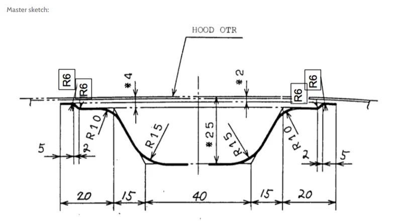
MASTER SKETCH:
The master sketch is prepared based on the requirements that received from marketability team and on basis of manufacturing requirements. It is a master section used for designing these Hood.
DESIGN OF HOOD OUTER PANEL
- It is created on basis of styling and it wraps around inner panel for fixing both together by applying mastic between them.
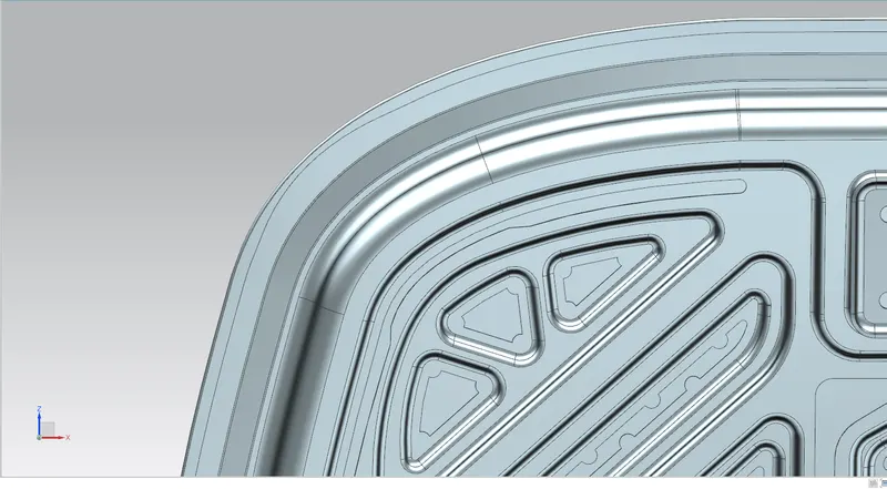
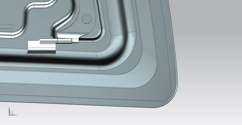
- Some reliefs are applied at the edges.
DESIGN OF HOOD INNER PANEL
- At first wave geometry is used to extract the styling surface as a linked body.
- Then these surfaces were trimmed into half along x-axis by using trim body.
- By using offset geometry of 0 mm were generated and separated to feature group for forming parent group and other one for working surface.
- On basis of master section their surfaces were offset at 2mm ,4mm and 25mm downwards.
- Then for creating flange the corner of the tangent curve will be offset inwards at distance of 20mm by giving filleted corner of 30mm further remaining portion to be trimmed.
- Though curves are applied to create flanges at 80 degree by applying tolerance for easy manufacturing.
- On third surface 55mm offset distance for curve has given and by removing unwanted portion.
- Then required embosses are created in a way that force dissipates and passes through corners which the energy is dissipated to outwards. Hence to satisfy the requirements of NASC regulations that embosses must have outward draft.
- By using edge blend with three corners all required surfaces are selected with proper directions and smoothened out as per manufacturer requirements.
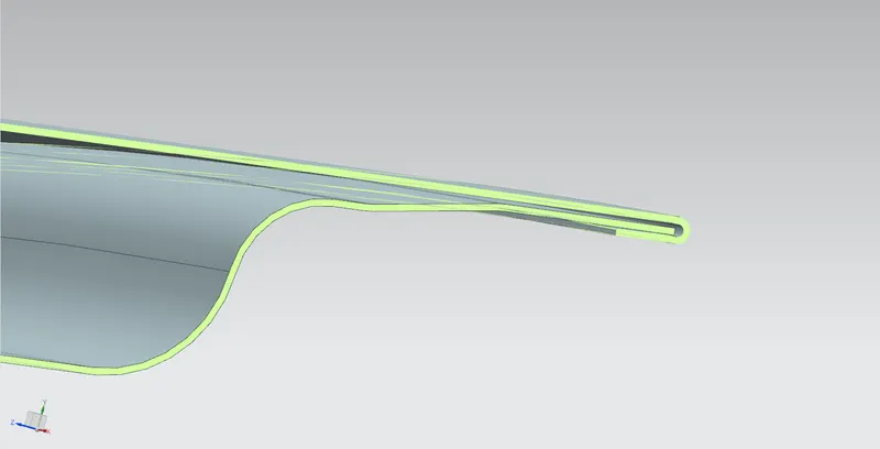
HEMMING
Hemming is a process of joining the both outer and inner panel together. These process roles and wraps the hood outer panel around the inner panel for holding it tightly together.
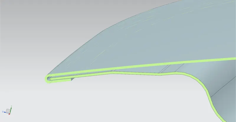
Front relief
Rear Relief
CLEARANCE FOR MASTIC SEALANT
ASSEMBLY OF HINGES ASSEMBLY
- Hinge assembly is carried out by applying required constraints.
- Initially inner panel was fixed, and line was created horizontally that connects the hinges were constrained with a parallel mate to x-axis.
- Then the top surface of hinge is constrained to hood part that is emboss on the inner panel.
ASSEMBLY OF STRIKER
- At first the latch was positioned roughly on basis of constraints and exporting the rear surface of latch using wave geometry linker.
- Then emboss for the latch was created before doing this some surface is extended all around for creating clearance for edge blends.
- Required circle from centre point on hinge axis is selected and a line tangent to circle and a line vertical to striker point from latch were created.
- Then both the lines were aligned then latch will have its perfect position for striking with the engine compartment.
- Now if we move the hood as closing then the striker will meet the exact location of striker point in the engine compartment.
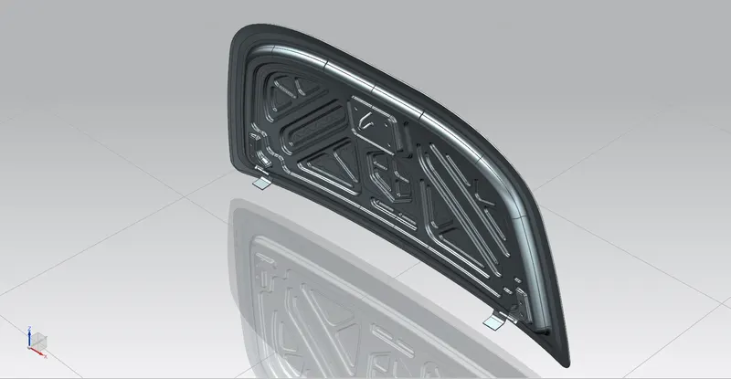
HOOD ASSEMBLY
ISOMETRIC VIEW
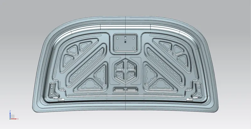
FRONT VIEW
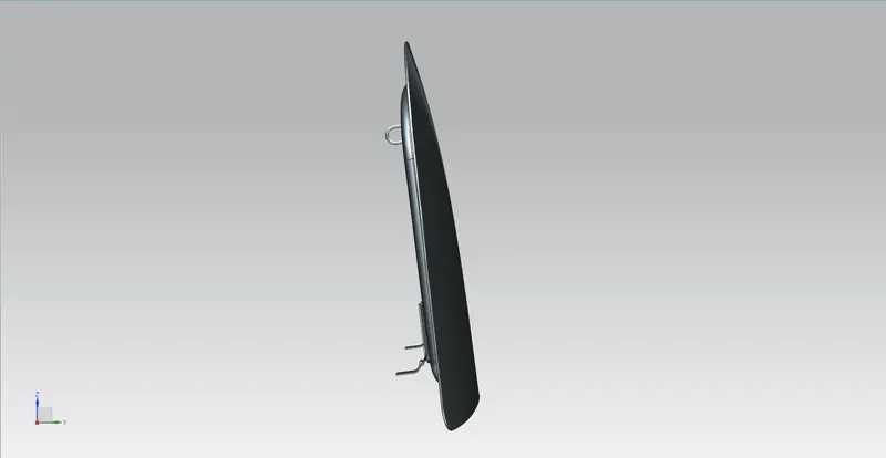
SIDE VIEW
TOP VIEW
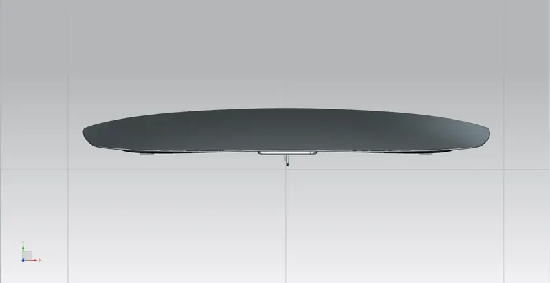
BACK VIEW
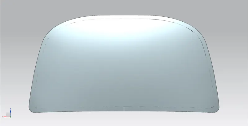
BOTTOM VIEW

CONCLUSION:
The Hood of the Car is Designed and Assembled under the given requirements using the SIEMENS NXCAD.
LINK:https://drive.google.com/file/d/1BUpKctyiM-84CSZtJ48fccVuPELj9sFm/view?usp=sharing