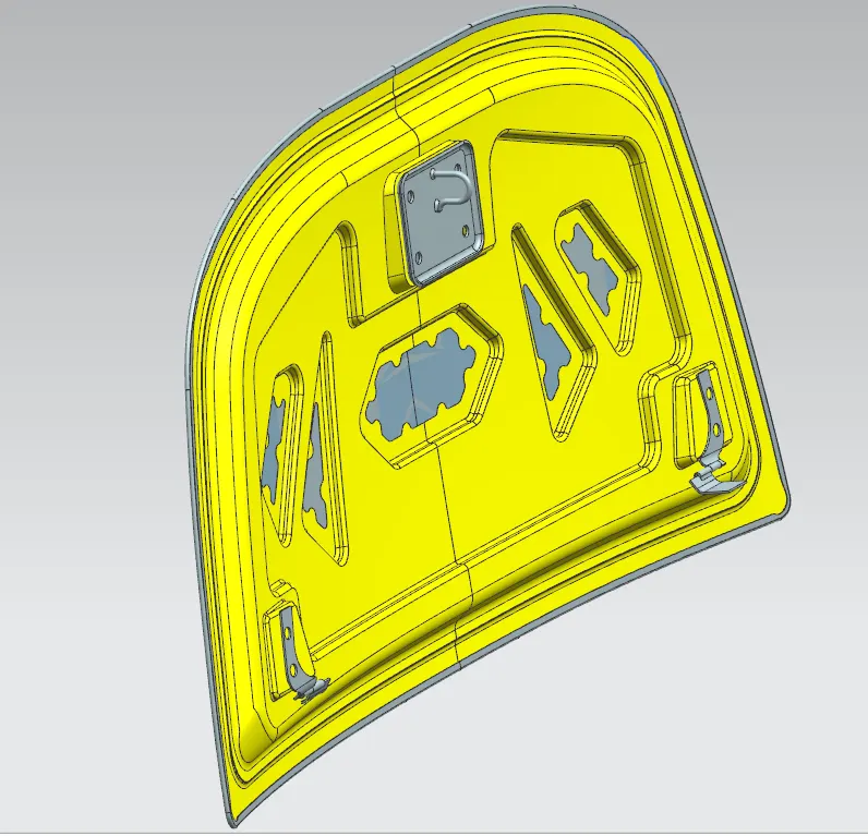
Hood design-Week 2
AIM:
Design Hood Outer Panel, Inner Panel and the necessary reinforcements by following the Master Section mentioned
The above diagram shows the master section for the hood inner panel.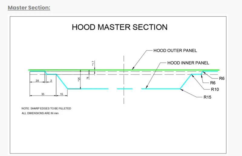
Step 1 :download all necessary parts.
Step2 : create a new assembly file in nx cad .
step 3:understand the master section of the given hood diagram.
Step 4 : add all the nessary parts in to the assembly file.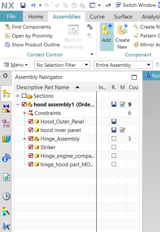
Step 5 : create a new model and name as hood inner panel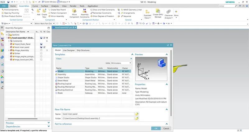
Step 6 : open the inner panel part model in the tree go to the ‘WAVE GEOMETRY LNKER’ in athe ASSEMBLY tab link the outer panel of the hood in to inner panel and untik the assosiate .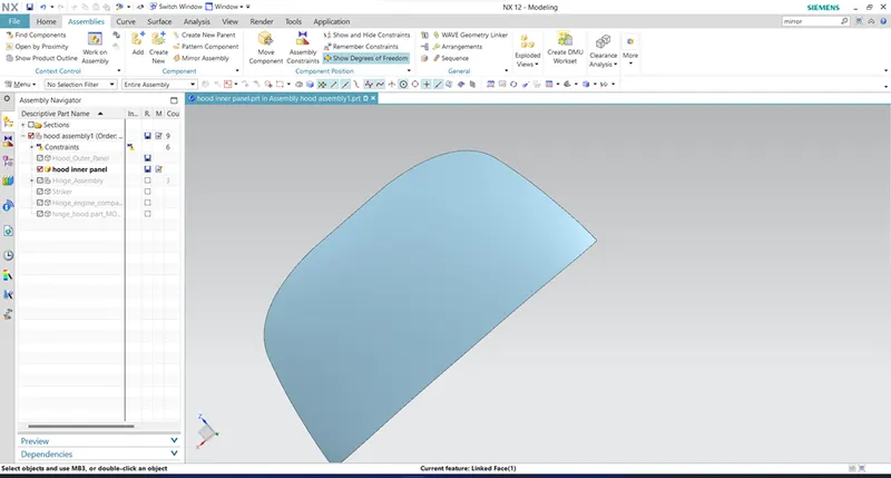
Step 7: create the tooling axis for the hood.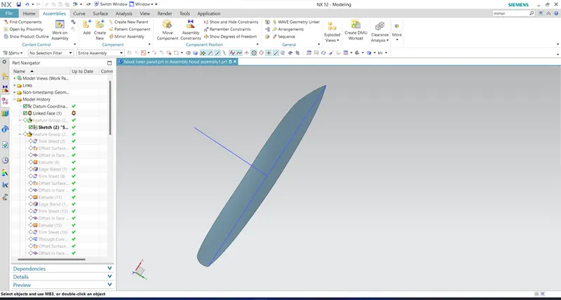
Deep drawing is a sheet metal forming process in which a sheet metal blank is radially drawn into a forming die by the mechanical action of a punch. It is thus a shape transformation process with material retention. The process is considered "deep" drawing when the depth of the drawn part exceeds its diameter.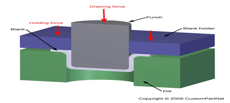
step 8: trim the sheet with respect to the plane for easy designing by using ‘TRIM SHEET’ I the ‘SURFACE’ tab.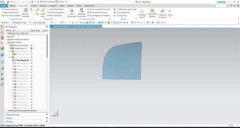
Step 9: create a ‘OFFSET SUTRFACE’ for the linked good for 2 mm given in the master section presented in the ‘SURFACE’ Tab.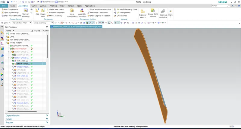
Step10: make a curve on the offseted surface by using ‘OFFSET CURVE IN FACE’ in ‘CURVE’ tab.for 20 mm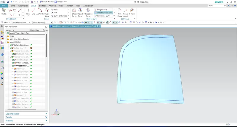
Step 11: Extrude the offseted curve by using ‘EXTRUDE’ comment present in the ‘HOME’ tab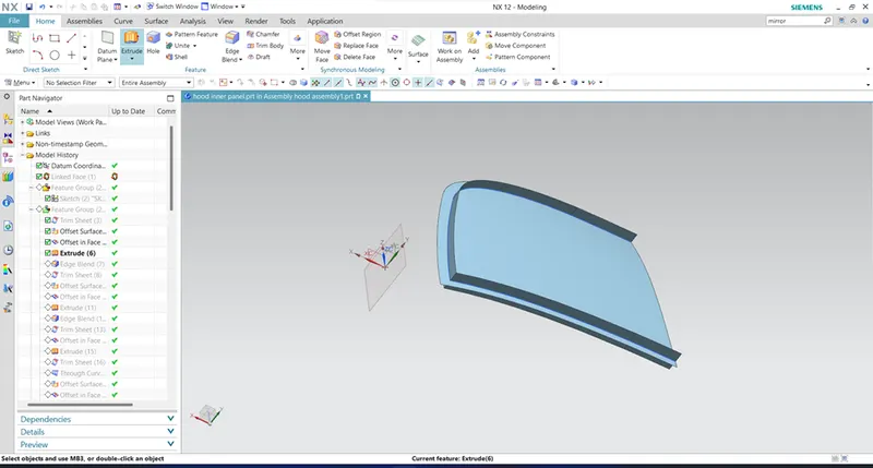
Step 12: fillet the shape edges of the extruded surface by using the ‘EDGE BLEND’ in the ‘HOME’ tab.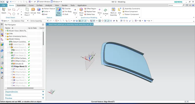
Step 12: trim the sheet with the hep of the extruded surface with the help of ‘TRIM SHEET’ in the ‘SURFACE’ tab.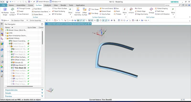
Step 13: offset the surface again for 4mm this time for secondary pojection give in the master section.
Step 14: repeate the above steps for create the second emboss.for 22mm offset curve in face.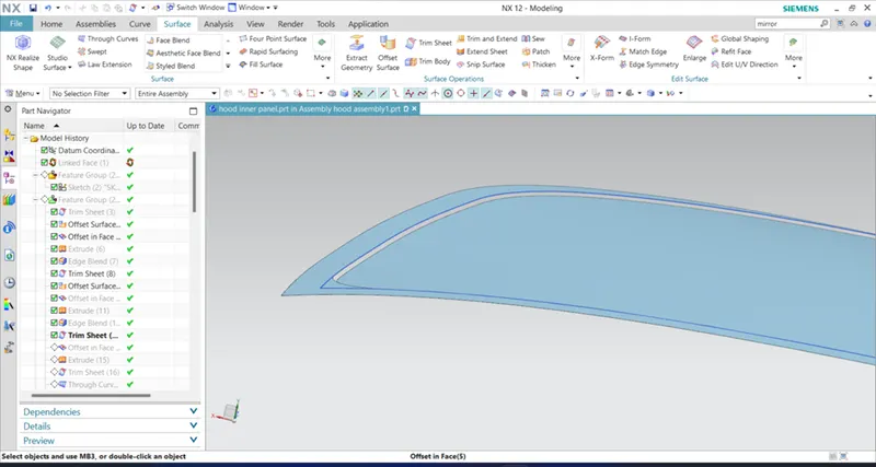
Step 15: again offset a curve in the trimed surface for 13 mm and trim the sheet w.r.t the cure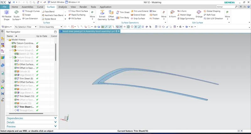
Step 16: join the two trimmed surface by using ‘THROUGH CURVES’ comment in the ‘SURFACE’ tab.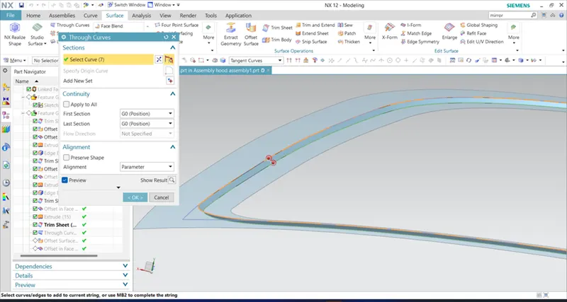
Step 17: do the above steps for the third projection.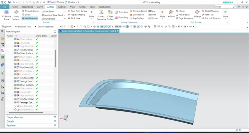
Step 18: make the sharp edges in to smooth curve surface for the give radius by using ‘FACE BLEND’ I the ‘SURFACE’ command.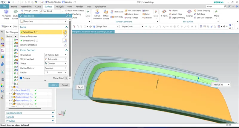
Step 19: create a sketch on the surface for the primary emboss of the hood by using ‘SKETCH’ in the ‘HOME’ Tab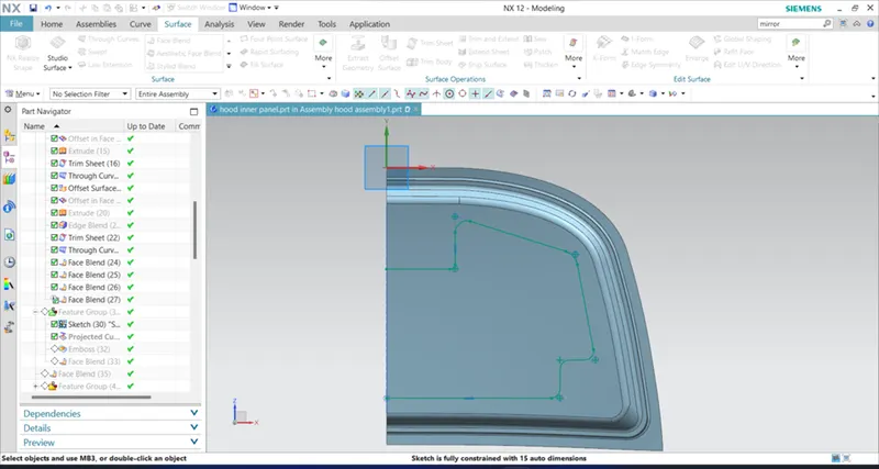
Step 20: project the sketch on the surface by using ‘PROJECT CURVE’ in the ‘CURVE’ tab.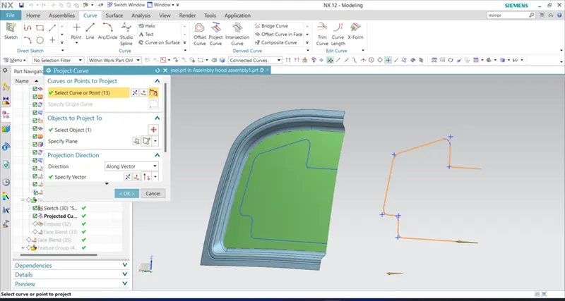
Step 21: with the help of the curve embossing the sheet by using ‘EMBOSS’ command in the ‘SURFACE’ tab.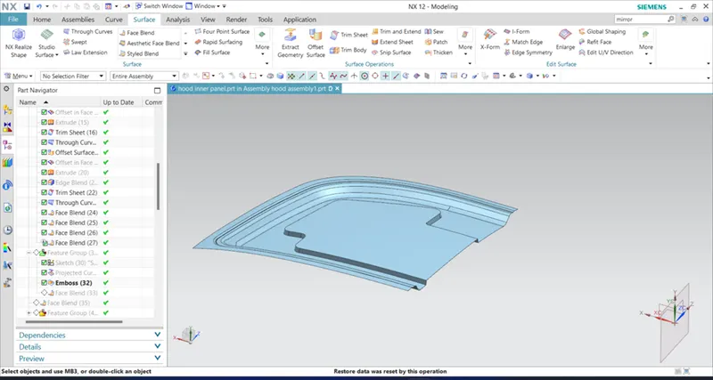
Step 22: blend the sharp edges of the embossed surface by using ’FACEBLEND’.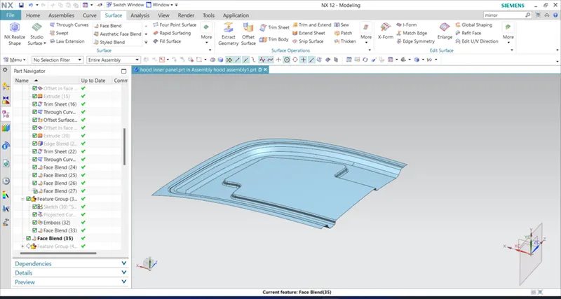
Step 23: Make Secondary Embosses of the sheet by do the above steps again.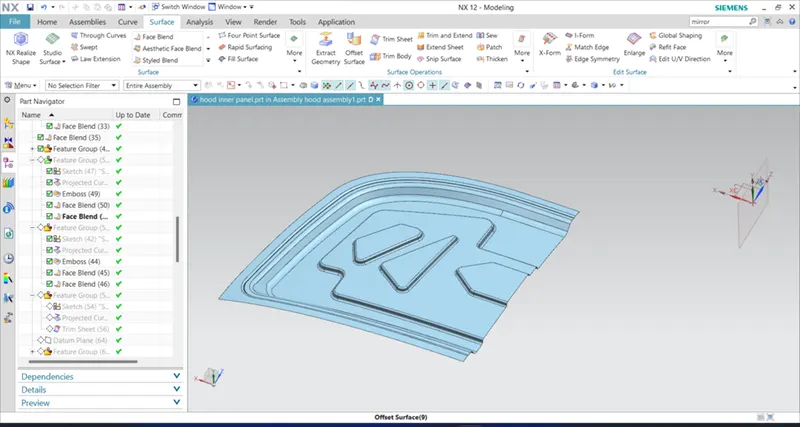
Step 24:Sketch and project the curves on the secondary emboss for the cutouts.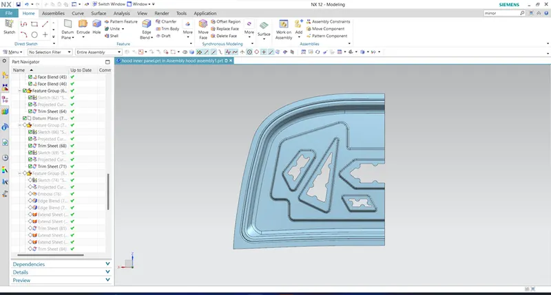
Step 25:mirror the geometry with respect to the plan by using ‘MIRROR GEOMETRY’ by serching in command search bar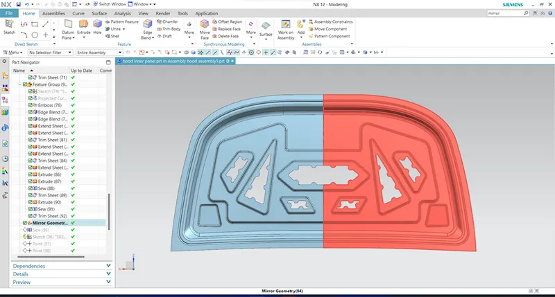
Step 26:assemble th hinges useng ‘ASSEMBLY CONSTRAIN’ in the ;ASSEMBLIES’ tab.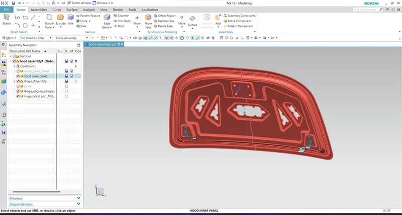
Step 27: assemble the striker as well as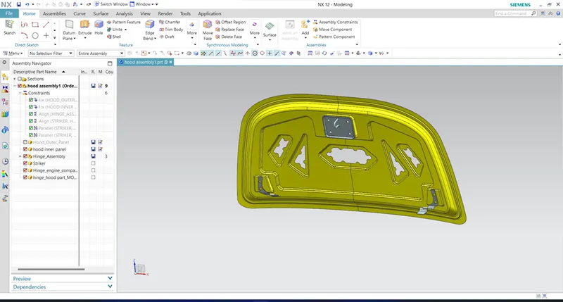
Step 28: finally thicken the inner panel for the thickness of 0.75mm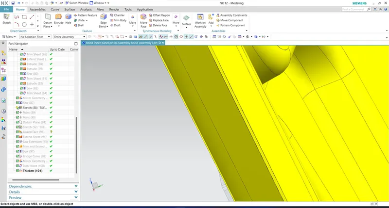
Step 29: go for the outer panel we suppose to hem the edges for the below dimensions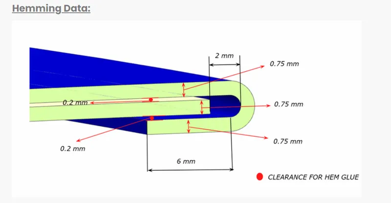
Step 30 : offset the surface to create the hemshape like below.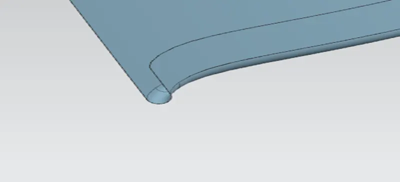
Step 31: Thicken the outer panel by using ‘THICKEN’ command.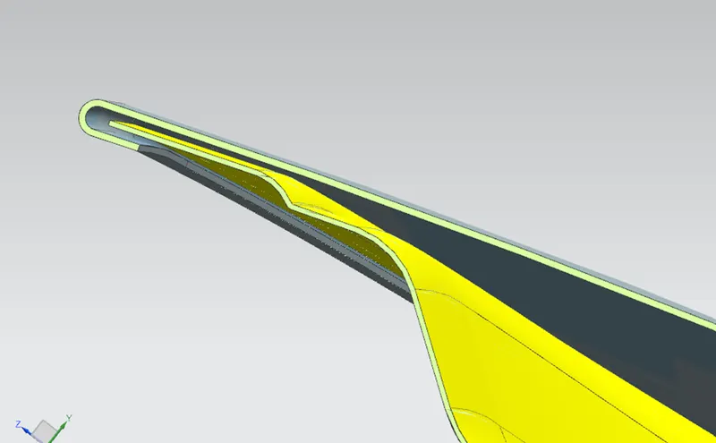
Step 32: make a clip section view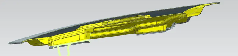
and the final out put looks like