Hood design-Week 2
Hood Design:
Objective:
To design a hood according to the provided master section and styling surface, Considering all the design constraints provided.
Input:
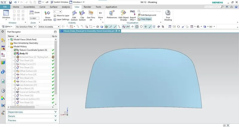
i. Styling Surface - Hood Outer Panel:
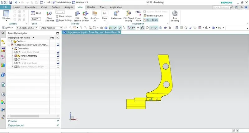
ii. Hinge Assembly:
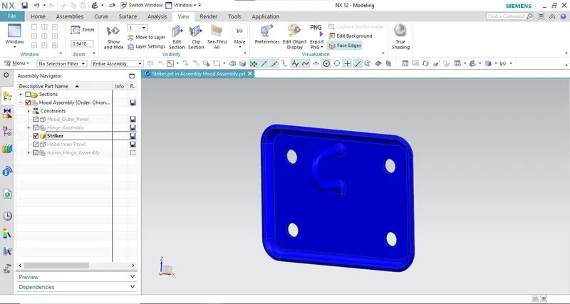
iii. Striker:
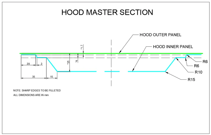
iv. Master Section:
v. Hood Thickness Information
- Outer Panel Thickness = 0.75mm
- Inner Panel Thickness = 0.75mm
- Reinforcement Thickness = 1.5mm
Design Considerations:
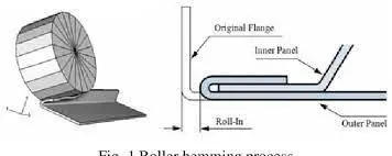
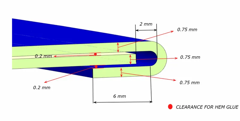
i. Hemming Data:
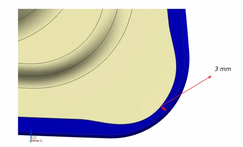
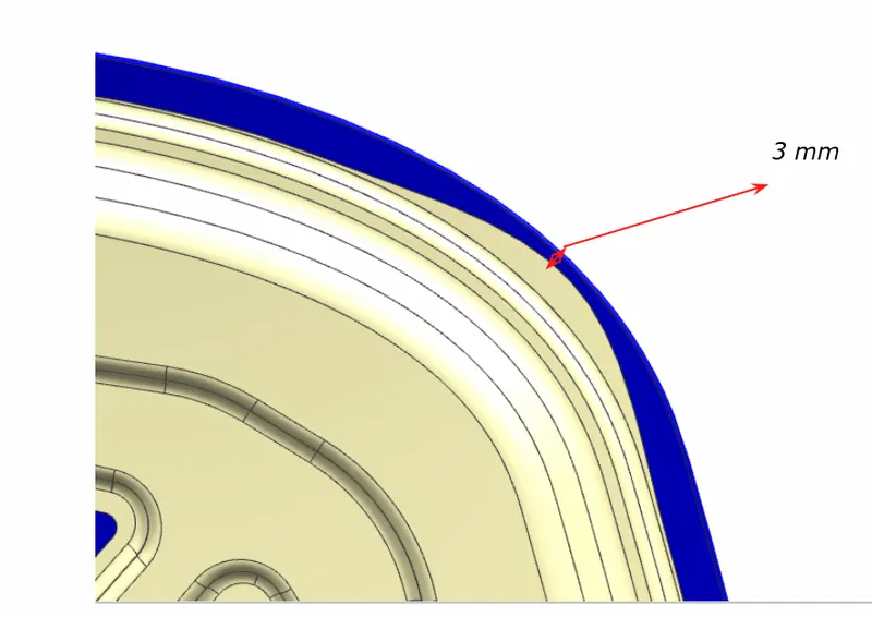
ii. Hem Relief:
Design Process:
a. Hood Assembly:
A new assembly file is created and named "Hood Assembly" and the following parts were added into the assembly file.
i. Hood Outer Panel
ii. Hinde Assembly
iii. Striker
b. Hood Inner Panel:
i. A new part file named "Hood Inner Panel" is created into the Hood Assembly File.
ii. A linked face was created from the hood outer panel without associative features.
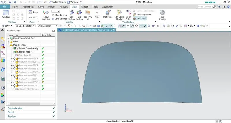
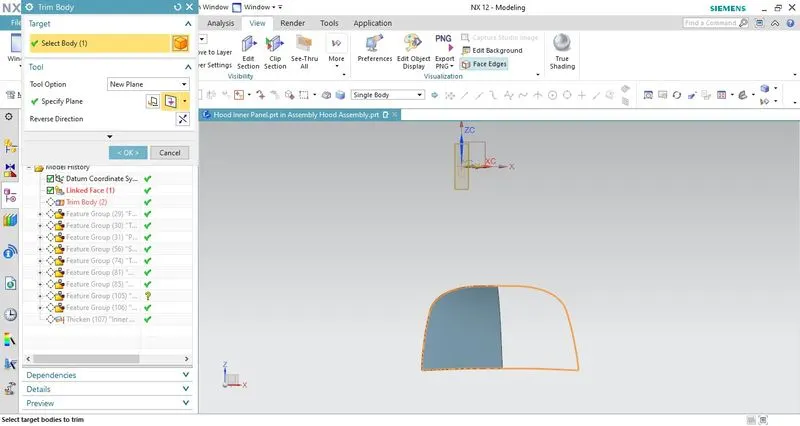
iii. The face is trimmed using the "Trim Sheet" command with respect to the center plane "XC" for ease of design.
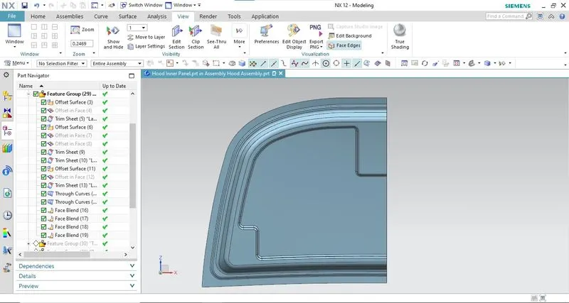
iv. Creating Flanges and Intital Emboss:
Multiple Flanges were created using "Offset Surface", "Offset Curve on Face", "Trim Sheet", and "Through Cures" as per the interpretation of the master section provided and the edges were blended using "Face Blend".
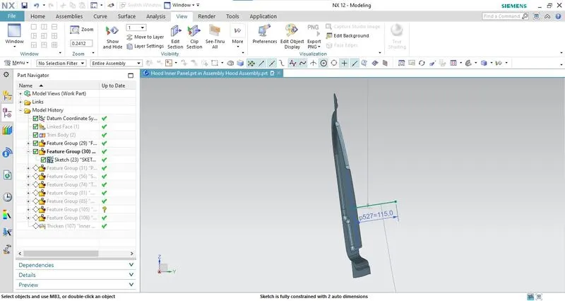
v. Creation of Tooling Axis: A tooling axis is created perpendicular to the Surface of the flange as shown in the image.
vi. Creating Primary Emboss:
The Primary emboss is created considering the space to mount the Hinge assembly and Striker.
- A sketch of the emboss was sketched on the "XZ plane".
- The sketch was then projected onto the sheet using the "Y vector".
- An emboss was created using the command "Emboss" on the face with the projected curve along the tooling direction for a distance of 10mm.
- The edges were blended using the "Edge Blend" command.
vii. Creating Secondary Emboss:
The secondary emboss is created considering the conditions like "Wrap Around Distance", "Head Impact Zone" and dispersion of the impact force along the hood towards the hinges to reduce the impact force when involved in an impact.
- A sketch of the emboss was sketched on the "XZ plane".
- The sketch was then projected onto the sheet using the "Y vector".
- Each individual shape from the sketch is embossed onto the sheet using the command "Emboss" along the tooling direction for a distance of 8.5mm.
- The edges were blended using the "Edge Blend" command.
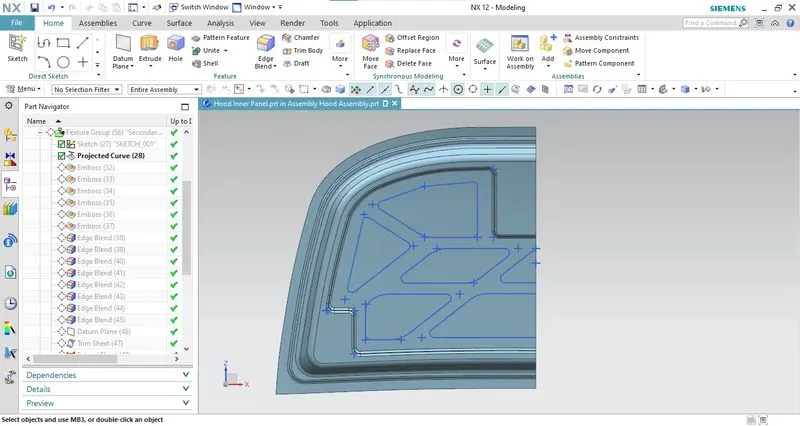
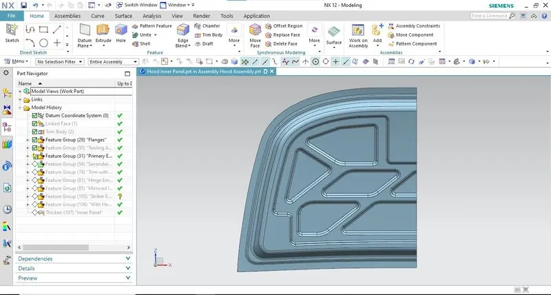
viii. Creating Mastic Points and Trim the Secondary Emboss:
- The Sketches from the secondary emboss were used to create an offset for trim on the "XZ Plane".
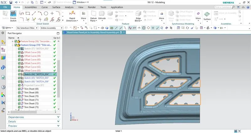
- The Mastic points were drawn along the edges of the trim profile created in a way that the mastic points are 20mm and the influence circle was 80mm. It was made sure that all of the trim profile was under the influence circles.
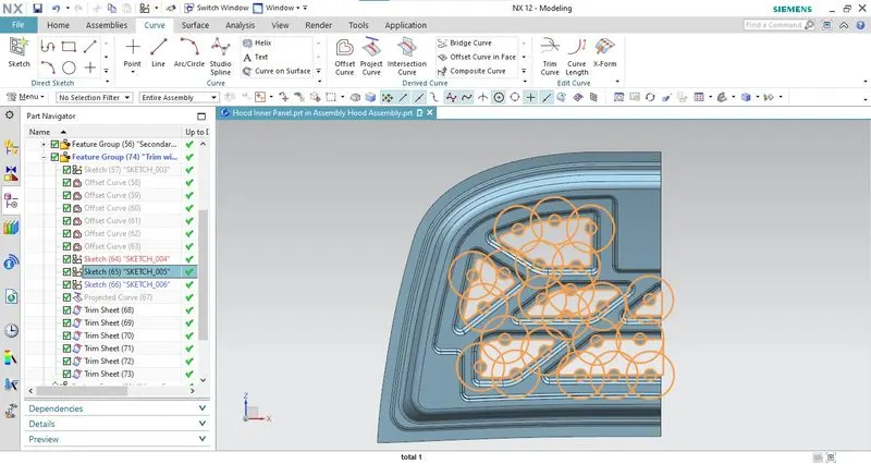
- The final trim profiles were created merging the trim profile created earlier with the mastic points.
- The Final Trim profiles were projected onto the sheet using the "Y Vector".
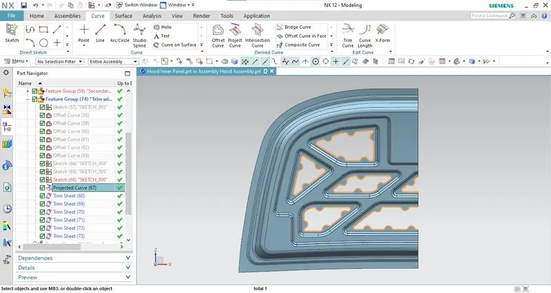
- Each trim shape was trimmed off from the sheet using the "Trim" command.
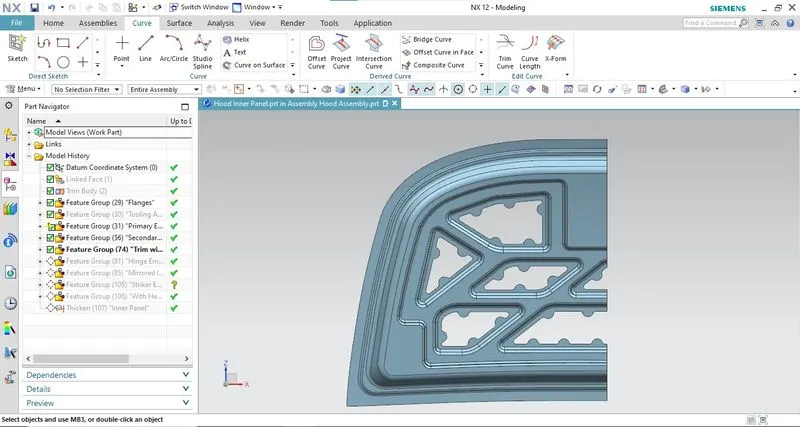
ix. Creating Hinge Emboss:
- A datum plane was created using the "At Angle" option from the "Datum Plan" command. The plane was placed at an angle where the plane was parallel to the sheet created.
- A Sketch was created on the created datum plane for the mounting of the hinge.
- The created sketch was projected on the sheet along the "Y Vector".
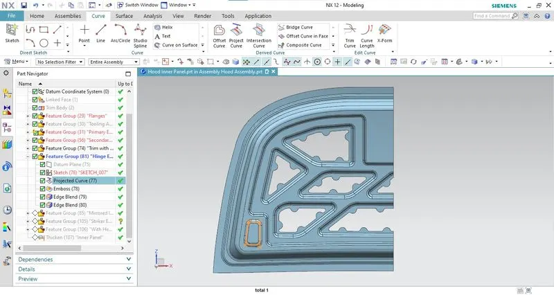
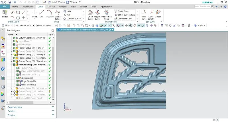
- The sketch was then embossed using the command "Emboss" along the tooling direction for the desired distance.
- The "Edge Blend" command was used for bending the edges.
- The hinge assembly was assembled by aligning the axis of the hinge and the "X axis" in Hood's inner panel. The rear face of the hinge is aligned to fix over the hinge emboss created.
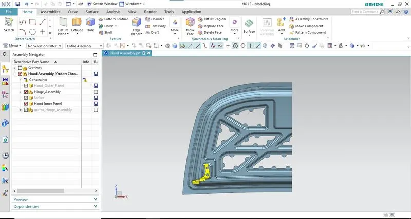
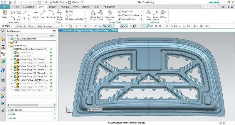
x. The created Inner Panel was mirrored along the XC Plane using the "Mirror Geometry" command from Menu > Insert > Associative Copy > Mirror Geometry and both sides were joined using the command "Sew".
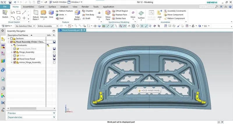
- The hinge assembly assembled earlier was mirrored using the "Mirror Assembly" command and the new part was created.
xi. Creating Striker Emboss:
- The hood hinge axis is created along the hinge axis of both hinges.
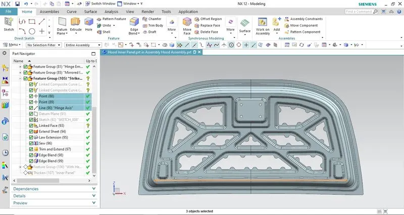
- The hood open trajectory was determined by creating a circle on a sketch along the hinge axis. A line was created at an angle from the horizontal axis which meets the circle. Another line was created at the intersection point which is tangent to the circle. this point will be the striker's latching point.
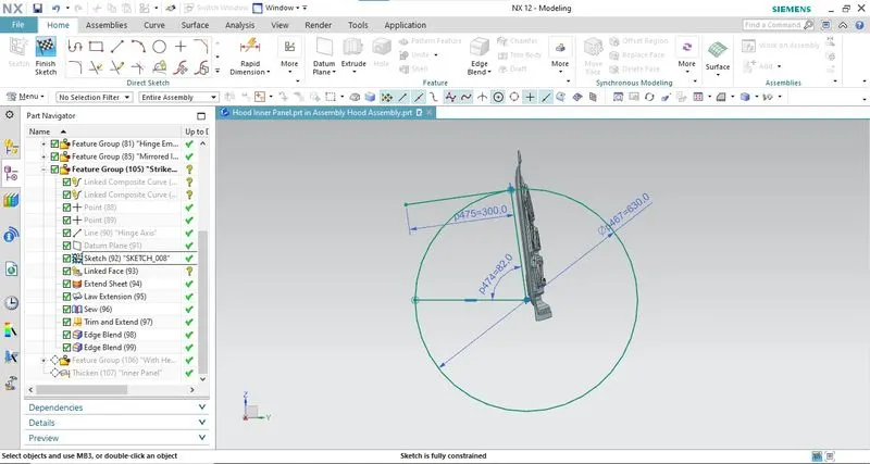
- The latching line was determined and drawn from the striker lock clamp. Also, the point of latching was determined.
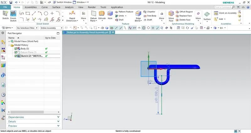
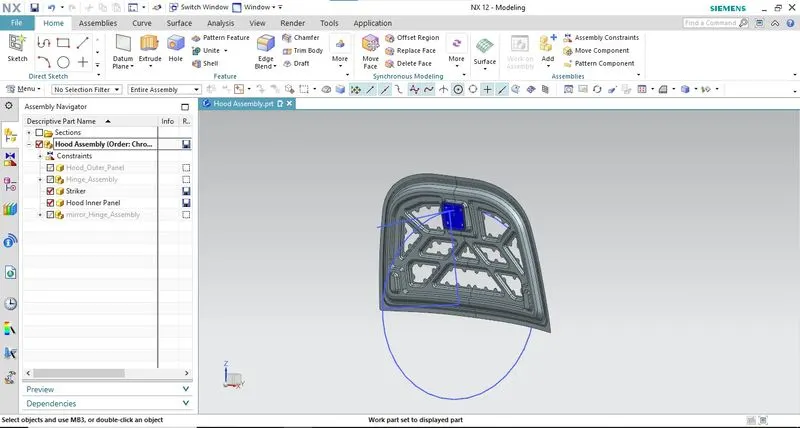
- Striker was assembled and constraints were made in a way that the latching point of the striker and the tangential intersection point in the Inner panel aligned with each other. Also, the tangential line in the inner panel is aligned with the line drawn along the striker clamp. Then the orientation was corrected by aligning the center plane of the hinge axis and the striker.
- The base of the striker is copied into the inner panel using the "Wave Geometry Linker" command.
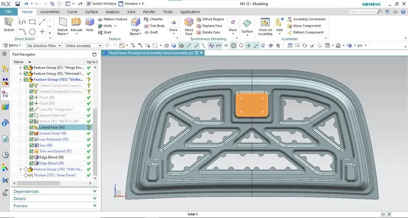
- This base sheet is extended further using the "Extend Sheet Command"
- The side walls were made using the "Law Extention" command for a positive draft angle.
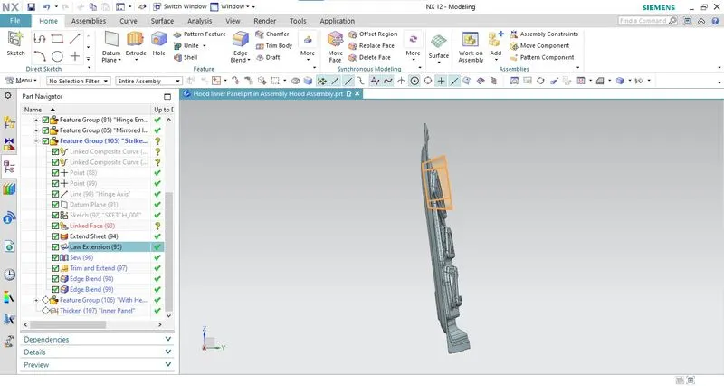
- The extended sheet and the law extension were joined together using the "Sew" command.
- This joined sheet is attached to the inner panel sheet using "Trim and Extend"
- The diameter of the circle and the angle of the intersecting lines from the sketch were altered in the best way to position the striker to the best fit.
- The Striker Emboss is created on the inner panel.
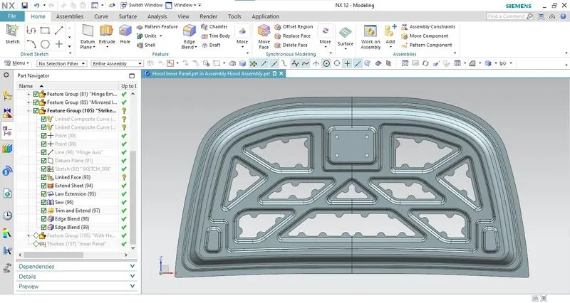
xii. Preparation of corners for Hem:
- A bridge curve was created at the sharp corner.
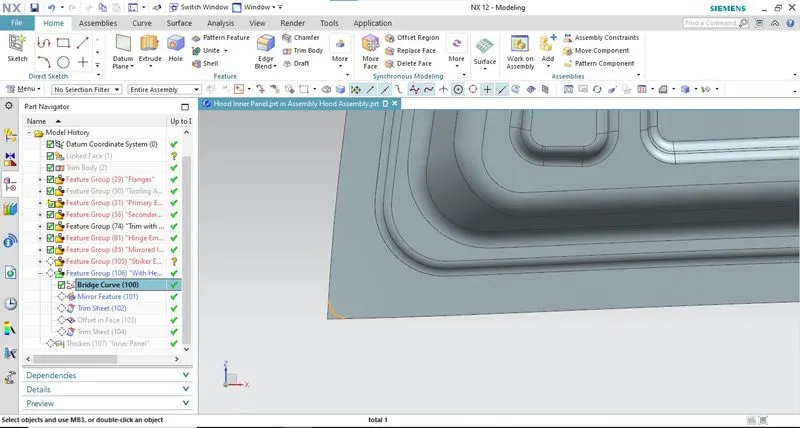
- The created bridge curve is mirrored to the other side using the "Mirror Feature" command and trimmed off from the inner panel sheet.
- Also, the Edged of the sheets were trimmed for 3mm for the hemming clearance using "Offset Curve on Face" and "Trim sheet" commands.
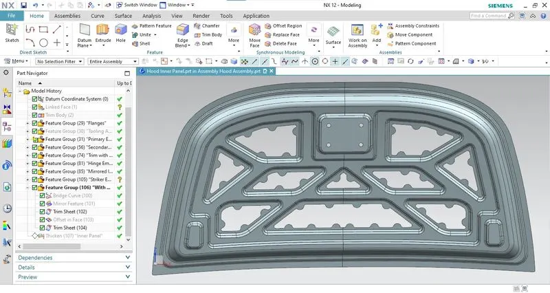
xiii. Creating Mounting holes for Hinges:
- The mounting holes from hinges are copied into the inner panel using the "Wave Geometry Linker" command.
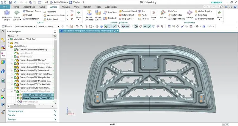
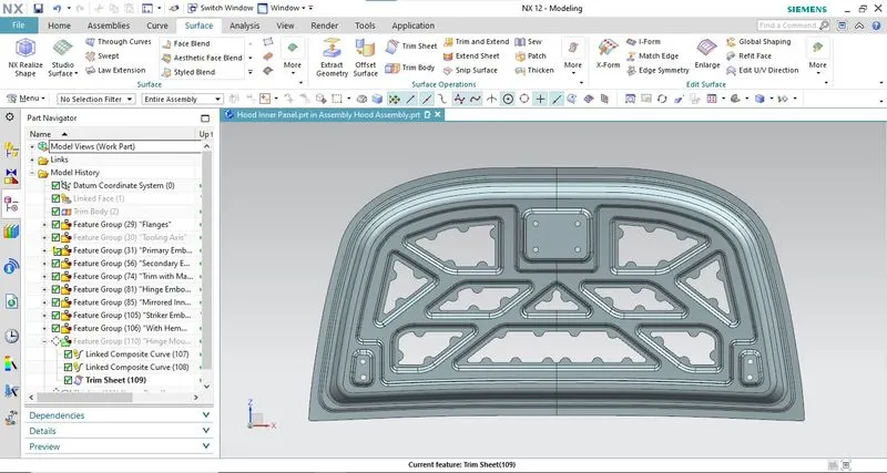
- The copied holes are trimmed from the surface using the "Trim Sheet" Command.
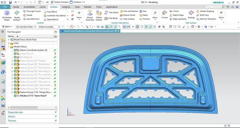
xiv. Thickening the component:
Thus created inner panel surface is thickened to 0.7mm to create the inner panel body.
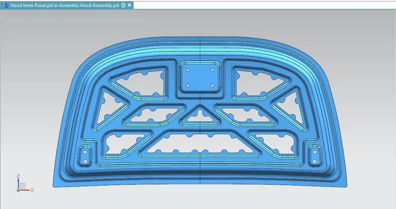
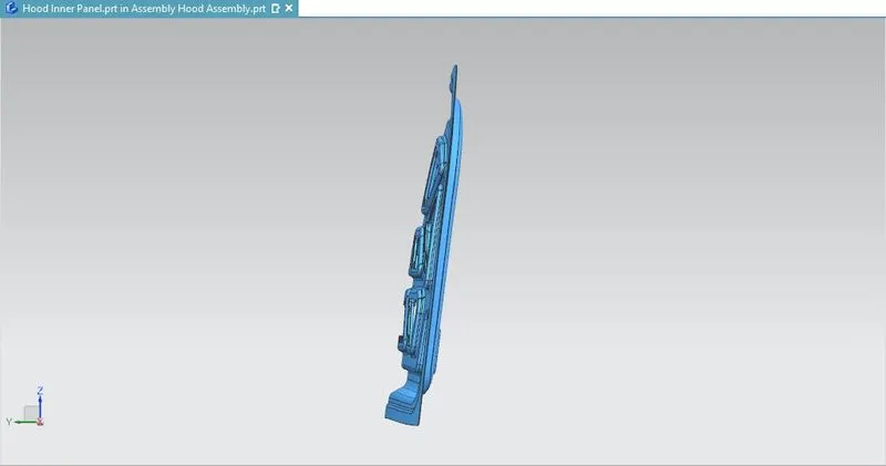
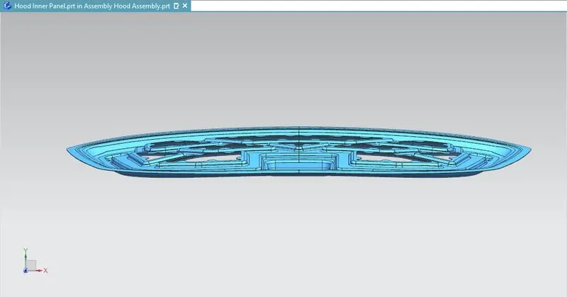
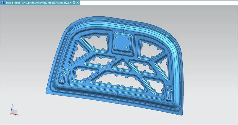
xv. Final Component - Hoof inner Panel:
- Front View
- Side View
- Top View
- Isometric View
c. Hood Outer Panel:
i. Creating Working Surface:
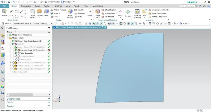
- The styling surface provided is copied using the "Extract Geometry" command.
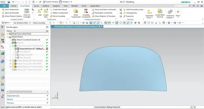
- The copied surface is trimmed into half using the "trim" command along the "XC Plane".
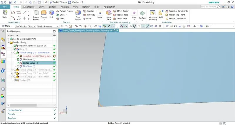
- A bridge curve is created at the sharp corners
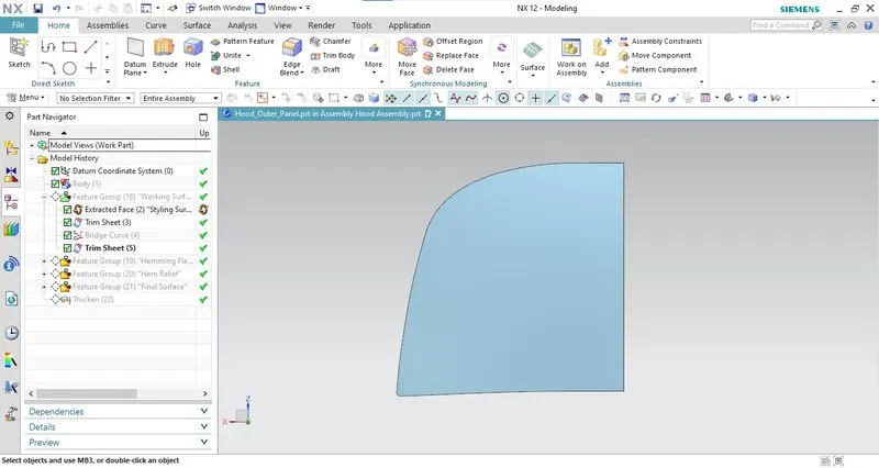
- The surface is trimmed with respect to the bridge curve created.
ii. Creating Hemming Flange:
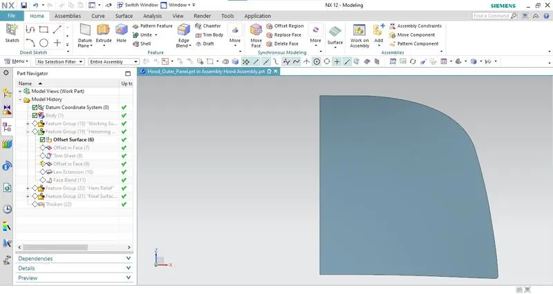
- The working surface is offset for a distance of 2.65mm (as per the hemming data) using the "Offset Face" command.
- The edge curves of the surface are offset for a distance of 7mm using the "Offset on Face" command.
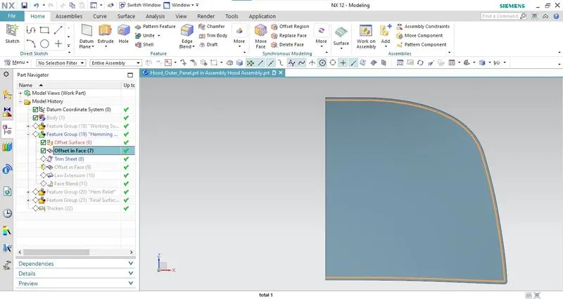
- The hem surface is trimmed along the offset curve using the "Trim Sheet" command.
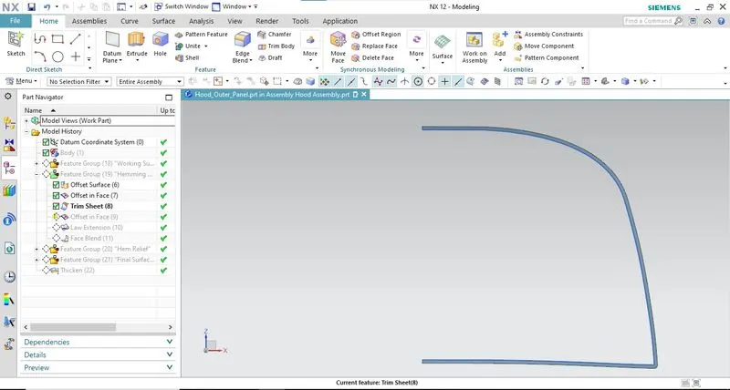
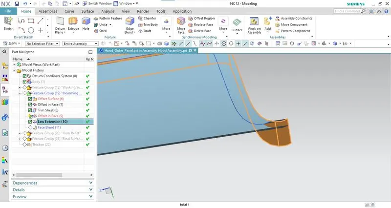
- Again an offset of minimum distance was done for the outer edge curve as the curve for the "Law Extension" command.
- Using the created edge curve, a law extension was created coinciding with the working surface.
- The "Three Face Blend" command was used to create a curved face continuity between the hem surface and the working surface.
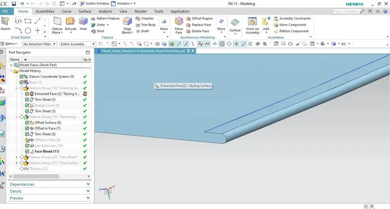
- The hem flange is created.
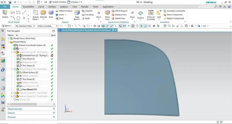
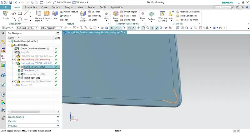
iii. Creating Hem Relief:
- A tangential curve was created on the hem face at the sharp-edged corner using the "Curve on Surface" command.
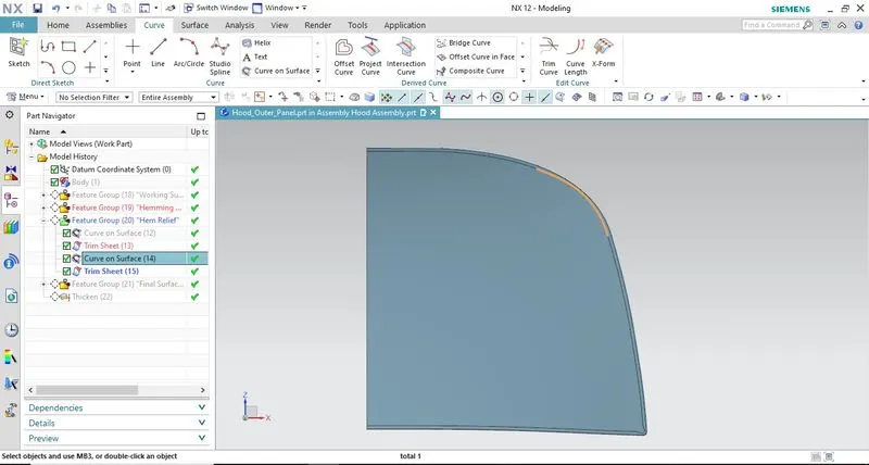
- Another tangential curve was created on the hem face at the lon radius curve using the "Curve on Surface" command.
- The hem face is trimmed with respect to the curves created using the "Trim Sheet" command.
- The Outer Panel with Hem Relief is created.
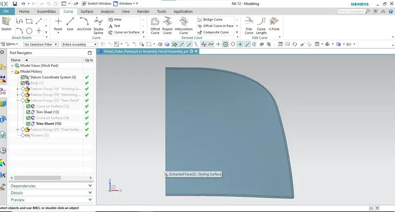
iv. Creating Final Surface:
- The created outer panel surface is mirrored along the "XC Plane" using the "Mirrored Geometry" command.
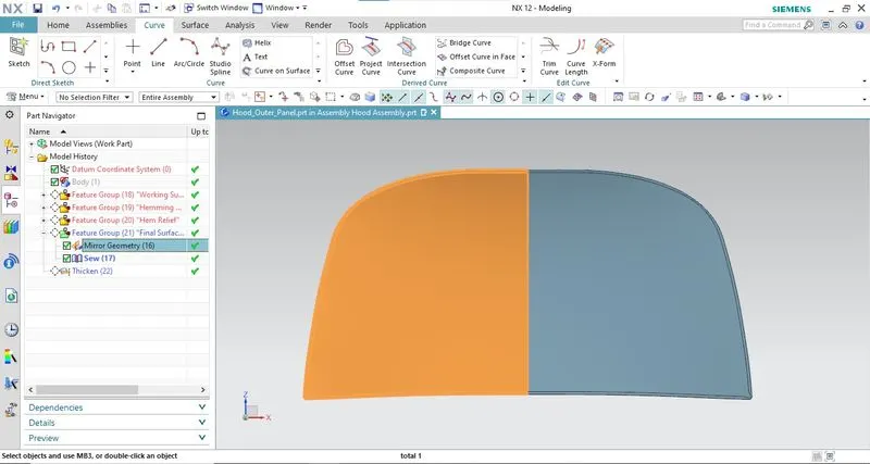
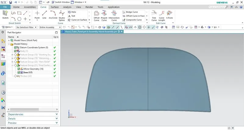
- The Actual surface and the mirrored surface are joined together using the "Sew" command.
- The final surface is ready.
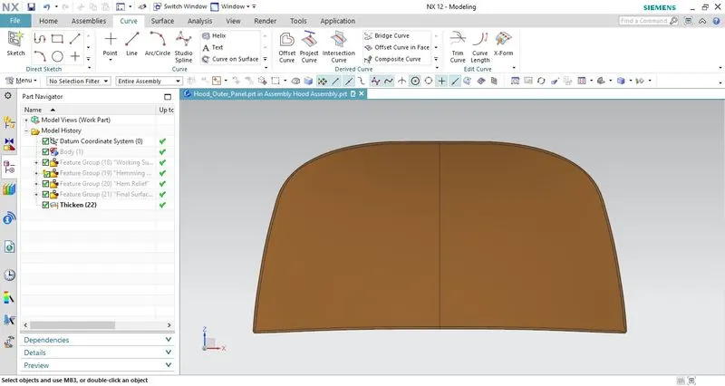
v. Thickening the component:
Thus created Outer panel surface is thickened to 0.7mm to create the Outer panel body.
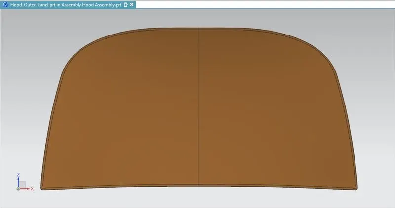
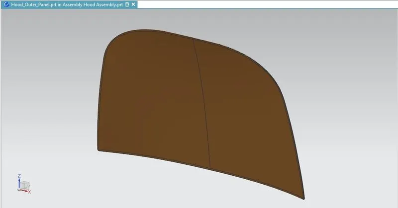
vi. Final Componet - Hood Outer Panel:
- Front View
- Side View
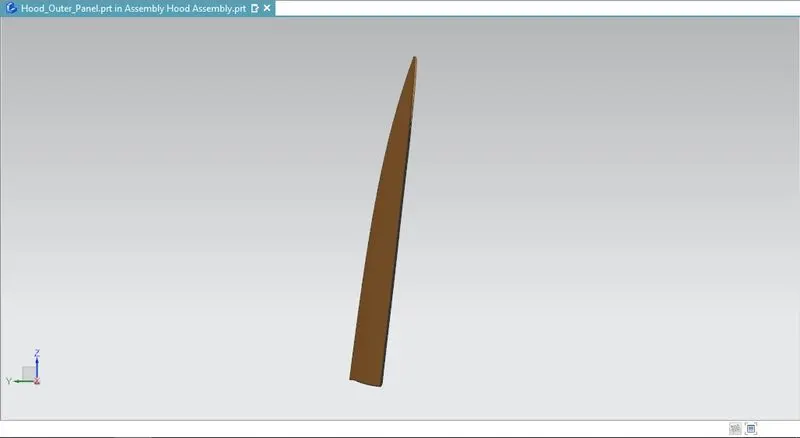
- Top View
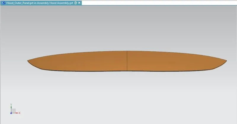
- Isometric View
d. Hinge Reinforcement - Left-Hand Side:
i. A new part was created with a file name "Hinge Reinforcement LH" using the command "Create New" from Assembly Tab.
ii. The face of the hinge mounting from the inner side of the Inner Panel is copied into the part file using the "Wave Geometry Linker" command.
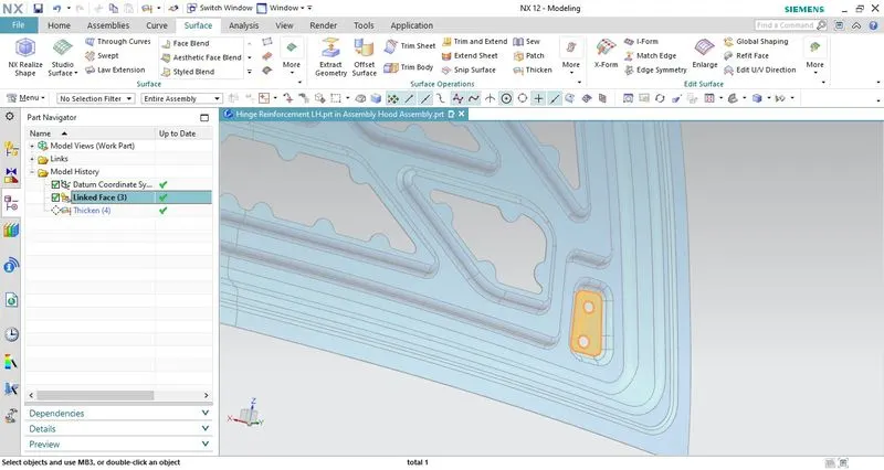
iii. The copied face is thickened to a thickness of 1.5mm.
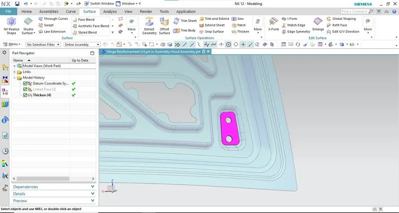
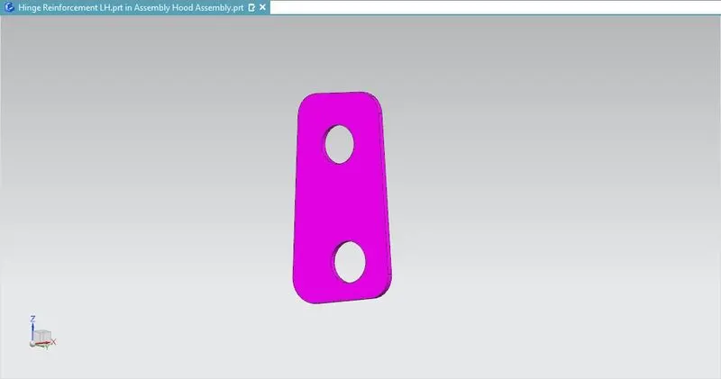
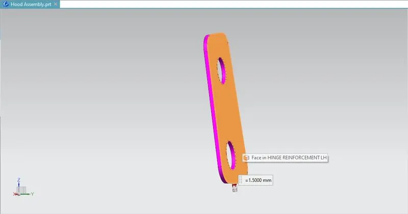
iv. Final Component - Hinge Reinforcement LH:
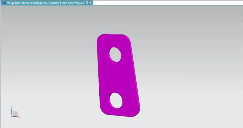
e. Hinge Reinforcement - Right-Hand Side:
i. A new part was created with a file name "Hinge Reinforcement RH" using the command "Create New" from Assembly Tab.
ii. The face of the hinge mounting from the inner side of the Inner Panel is copied into the part file using the "Wave Geometry Linker" command.
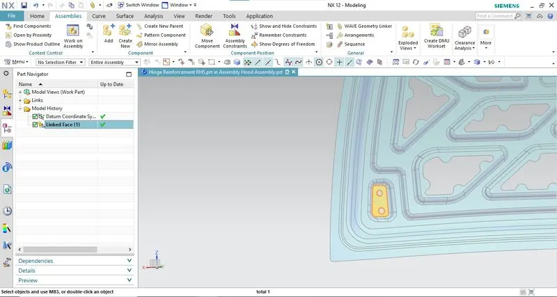
iii. The copied face is thickened to a thickness of 1.5mm.
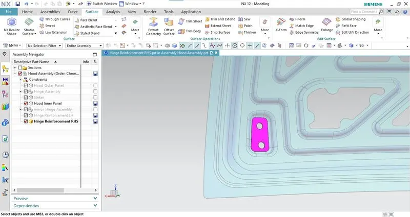
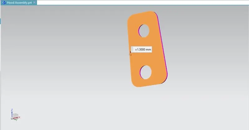
iv. Final Component - Hinge Reinforcement RH:
f. Striker Reinforcement:
i. A new part was created with a file name "Striker Reinforcement" using the command "Create New" from Assembly Tab.
ii. The face of the Striker mounting from the inner side of the Inner Panel is copied into the part file using the "Wave Geometry Linker" command.
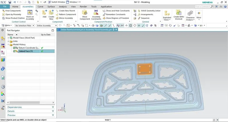
iii. The copied face is thickened to a thickness of 1.5mm.
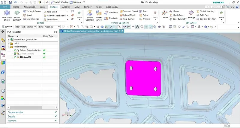
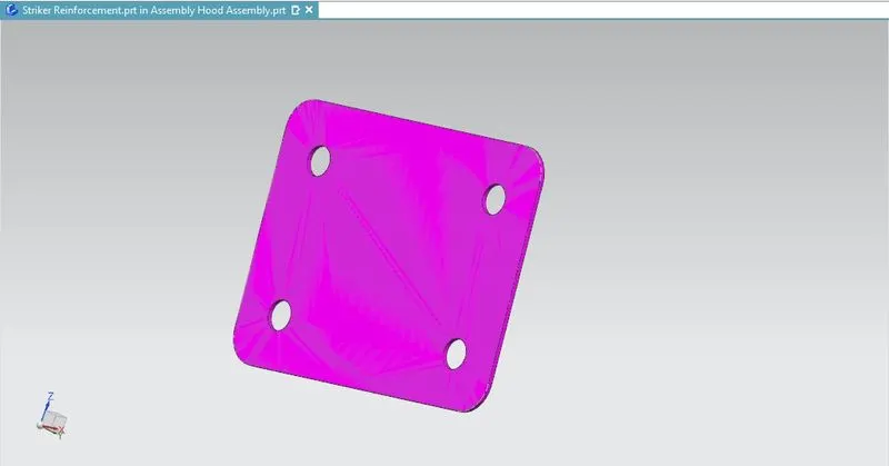
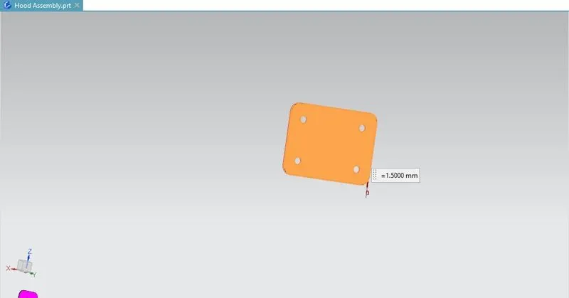
iv. Final Component - Striker Reinforcement:
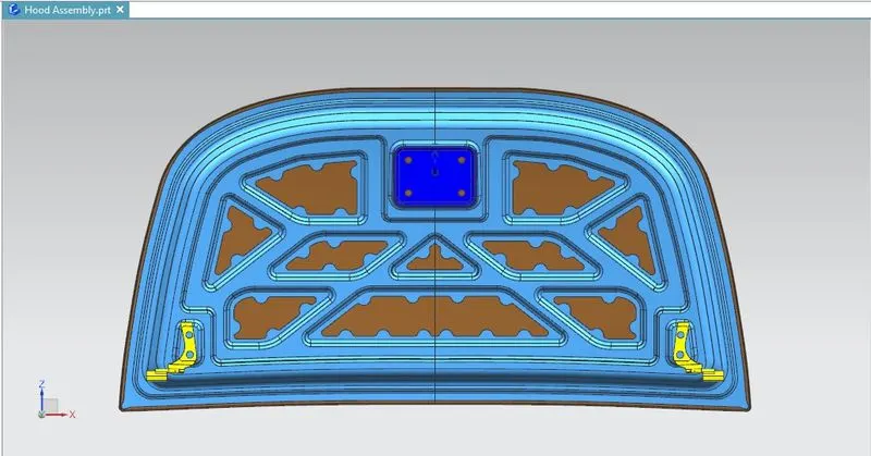
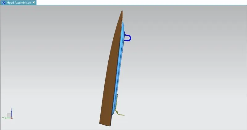
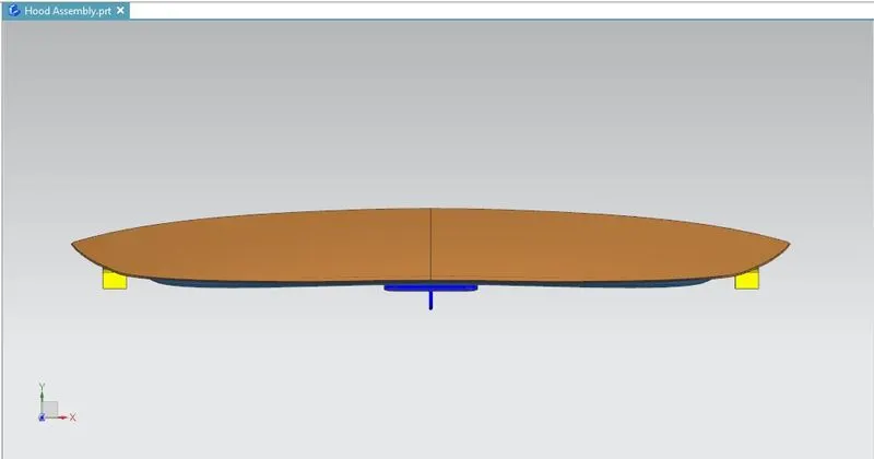
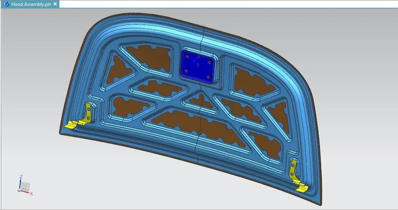
g. Hood Assembly:
- Front View
- Side View
- Top View
- Isometric View
Verification of Design Parameters:
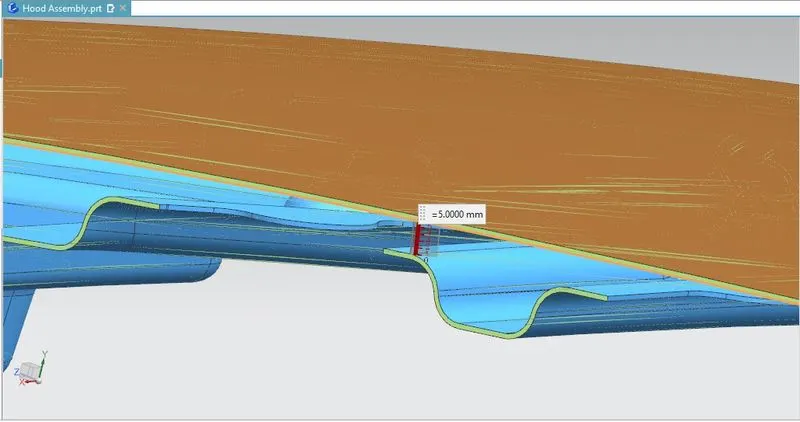
- The distance between the mastic points and the outer panel is 5mm.
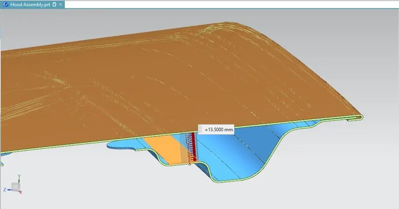
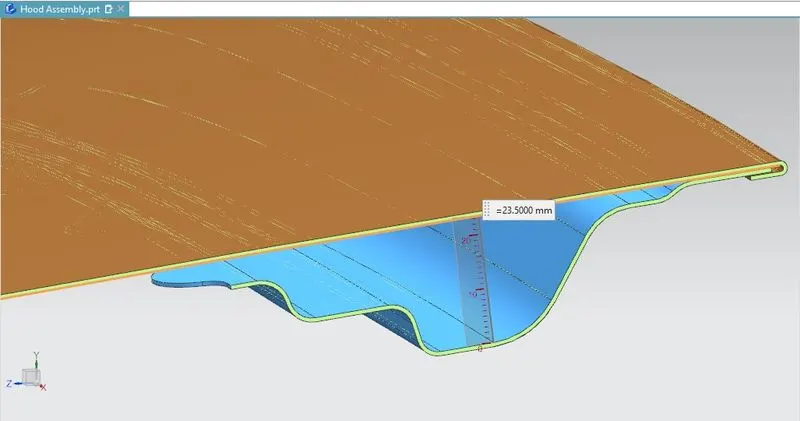
- The flange and emboss distances are as per the master sections.
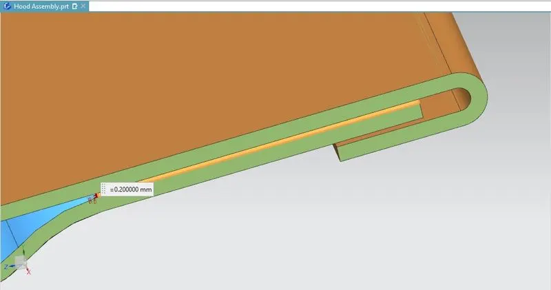
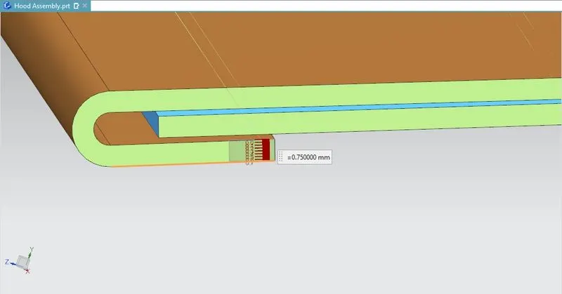
- The gap for hem glue is 0.2mm
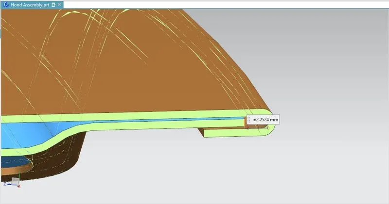
- The distance between the inner panel and the hem curve is greater than 2mm
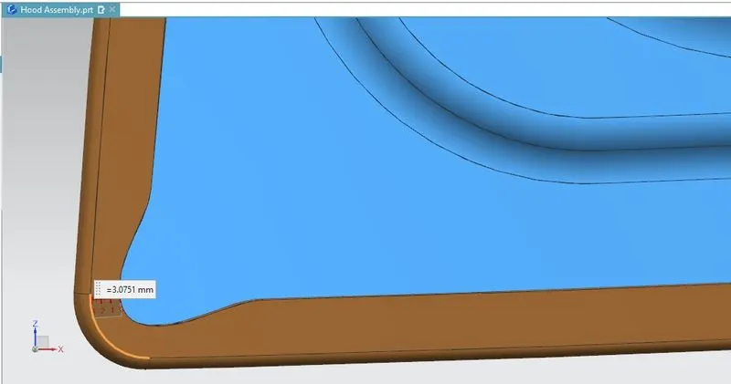
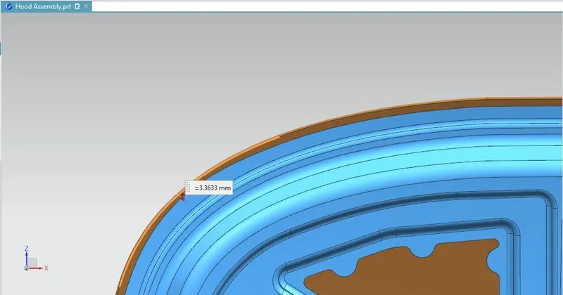
- Hem relief provided are greater than 3mm.
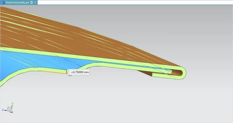
- The thickness of both Inner and outer panels is 0.75mm.
- The thickness of reinforcements is 1.5mm.
Manufacturing Process:
The manufacturing processes used in the manufacturing of Hood are discussed below.
i. Deep Drawing:
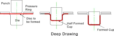
The sheet metal blanks are transformed into the desired shape using the process called "Deep Drawing". It is the process of forming a sheet of metal by radially drawing it into a forming die using mechanical force. It is a shape transformation process with material retention.
In this process, the blank is placed over a die with a hollow shape in it. The blank holders will be used to hold the blank in order to avoid wrinkles along the flanges while drawing. This also provides controlled material flow. Another die with the embossed shape is pressed over the blank where the blank is formed into a shape by pressing it in between two parts of the dies.
ii. Punching:
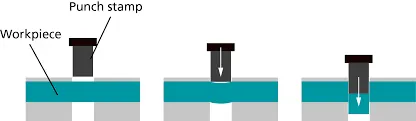
The Deep drawn blank will be under a process called "Punching" to remove the unwanted areas in the deep-drawn sheet. It is a process similar to deep drawing, but instead of retention of the material, the material will be removed completely. The deep drawn sheet is placed over a hollow die over which an embossed punch is pressed with higher mechanical force where the punch area is chipped and removed from the sheet.
iii. Hemming:
Hemming is the process of pressing the hem flange of an outer panel over the inner panel to create a firm joint without affecting its outer finish. It is mostly used in the components where the aesthetic look is of great importance.
Hemming is the process used for joining two different panels of a component with retaining the finished appearance on the outer side. For example, the inner panel of a hood or a tailgate will be placed over the outer panel, and the hem flanges are bent over these inner panels using various hemming methods. This gives us a firm joint between the panels.