Hood design
1.1 Aim:
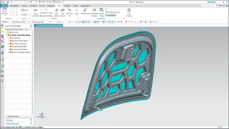
To design Inner Hood Panel from Class A Surface( Hood Outer Panel) and Master Section. The Hood should be designed considering the Hood Opening Angle and Passenger and Pedestrian safety.
2.1 Introduction to HOOD:
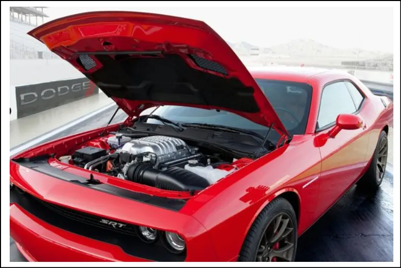
The hood or Bonnet is a part which comes under the subsystem of Closures in BIW and it will be placed in the front side of the car to provide an aesthetic look and to provide cover to the Engine system. It is a vital component considering frontal crash, and pedestrian safety and it can also affect the overall aerodynamics of the car. This Hood should be able to open and close just to get access to the engine system for Inspection, Maintenance and Repair. The hood is an assembly of an Outer Hood Panel, Inner Hood Panel, Latch and Striker and Hinges.
Some of the important Manufacturing processes that are carried out for the Hood are Deep drawing, Hemming, Riveting and Spot welding. Steel, Aluminium and Carbon fibre are some of the materials that are used for making hoods.
2.1.1 Metal Stamping:
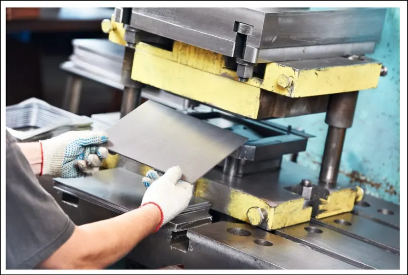
Sheet Metal Stamping is a process which is followed to give a specific shape to flat sheet metal. The metal will be fed into the press, where the die which is the stamping tool will be pressed into or through the metal with tremendous force to create the desired force. Punching, Embossing, Coining, Bending and flanging are all stamping techniques that are used to give shape to the metal.
2.1.2 Deep Drawing:
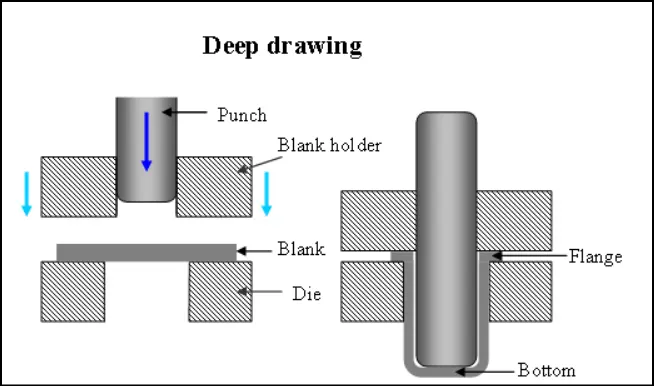
It is also one type of Metal Stamping, where the sheet metal blank is drawn into the forming die with the mechanical action of a punch. It is a shape transformation process with material retention. The process is considered "deep" drawing when the depth of drawn parts exceeds its diameter. Also, the desired shape will be attained by redrawing the part through a series of dies. Some of the common applications and products that are manufactured by using the deep drawing method are Automotive components, Electronic relays, Aircraft Parts, utensils, cookware and more.
2.1.3 Hemming:
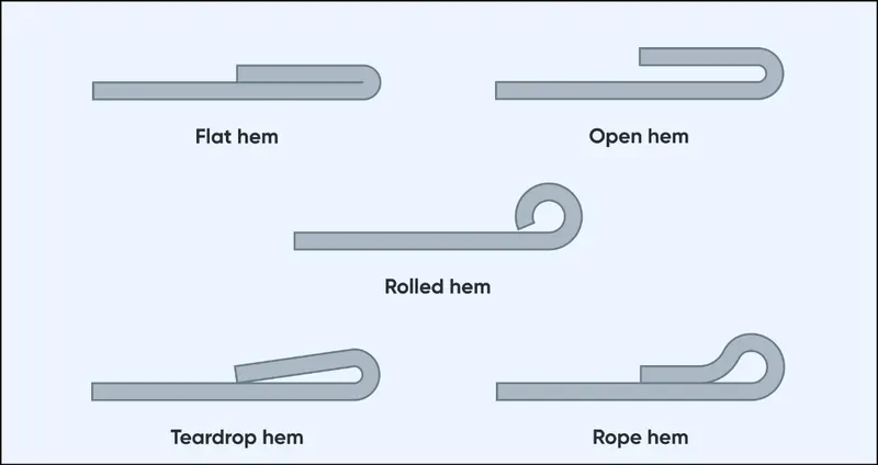
It is a forming process where the sheet metal edges are folded or folded over one another to create a snug fit by a roller. By using this process we can join to sheets without interfering with their look, especially the aesthetic look of any class A surface. In an assembly, hemming is considered a secondary operation after, trimming, flanging and deep drawing operation to join two sheet metal parts together. Automotive body panels and automotive parts such as deck lids, trunk lids, doors, hoods and tailgates are formed by using the hemming process.
3.1 Design Considerations of Hood:
For the design of the Hood, some limitations are to be considered and they are, Hood opening angle, Pedestrian Safety, Passenger Safety, Mastic Data(NVH) and Latch Trajectory.
3.1.1 Hood Opening Angle
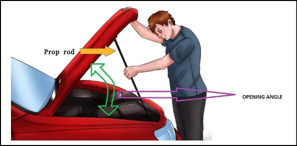
When the Hood is completely open it should not hurt the person who is standing next to the hood. For that, the opening angle of the Hood will be different based on the average height of the people in that particular region. The higher the average height, the opening angle will also be increased. This angle will vary from region to region, where the Manufacturing companies will decide based on where they gonna launch the car.
3.1.2 Pedestrian Safety (WAD):
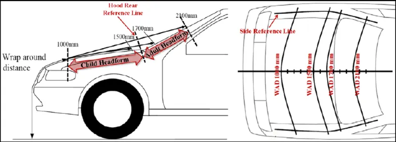
The distance between the ground and the evaluated areas of the cars which is said to be Wrap Around Distance (WAD) is measured according to the length of the area where the pedestrians’ heads are hit in accidents. The impact location area for adults' and children’s heads is set based on the data of actual accidents. In the crosswise direction, the sideline of the impact test area is from the line obtained by tracing the contact points between a straight edge and the side of the bonnet where the straight edge, contacts the bonnet bumper at 45 degrees (Bonnet Side Reference Line) to the inside half diameter of the head impactor. These points to be considered will the design of the hood.
3.1.3 Passenger Safety (Emboss Definitions):
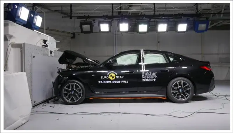
When a car is under a frontal collision, the force of the impact should be redirected to the outside of the car and not inside where the passenger will be placed. For that we would be defining the hood inner panel with embosses in a way that would deflect the force outwards.
3.1.4 Mastic Data (NVH):
Mastic is an adhesive which is used to make bonds between the exterior automotive panels to the vehicle's inner automotive panels like hoods, roofs and doors. It is a synthetic rubber sealant that remains elastic after curing to reduce panel flapping and prevent panel distortion. A single mastic point of 10mm has a cover from 60mm to 80mm. This also improves the vehicle's NVH (Noise Vibration Hardening).
3.1.5 Latch Trajectory:
Latch trajectory is a curved path which allows the latch and striker mechanism to close properly. For that, both hinges were joined using a line which forms a hinge axis and in that, and a circle will be drawn in the middle of it. The radius data would be provided based on where the striker is placed. This trajectory would determine the rotation of the hood.
4.1 Design Procedure:
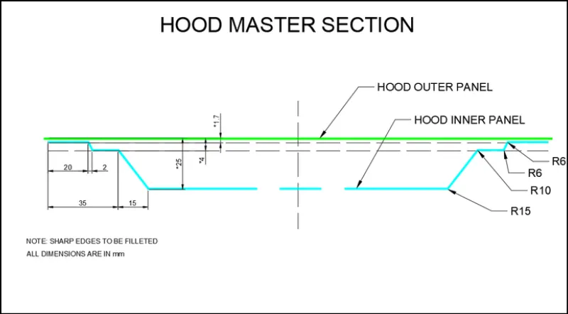
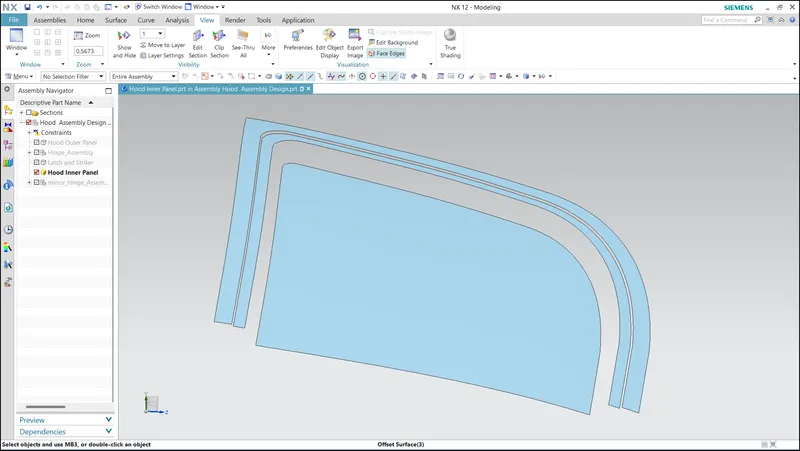
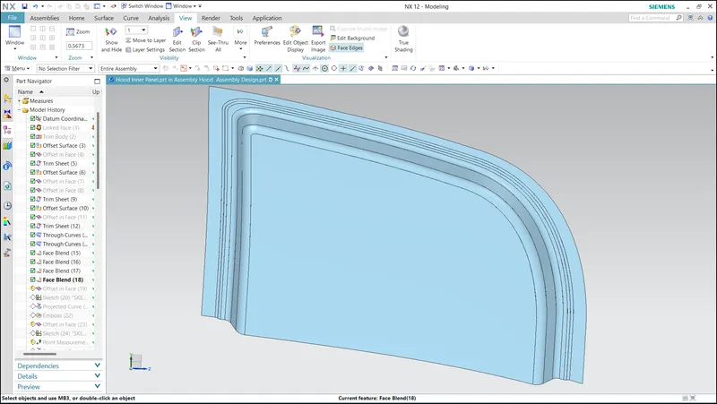
With the class A surface which is the hood's outer panel will be the base to design the hood inner panel. The hood inner panel is symmetry along yz plane so it is trimmed along yz plane. A copy of the hood's outer panel was taken with the help of the wave linker geometry tool ( Without associative), and the edge's faces were offset and trimmed as per the master section. Then the trimmed faces were joined using through curves and provided face blend as per in the master section.
Master Section:
Offseted and Trimmed faces:
Face blended sheet:
Now the total gap between the inner and outer hood is 25mm. That 5 mm will be needed for mastic sealant and 1.5mm will be needed for the thickness of the inner and outer hood panels. So, the embosses should be built at 18.5mm to fill the gap. An emboss with a height of 18.5mm would be unstable so, it would be built as 1st and 2nd embosses as 10mm and 8.5mm. These emboss were created by using emboss tool after leaving approximate space for hinge and latch and striker reinforcements.
Creation of Embosses:
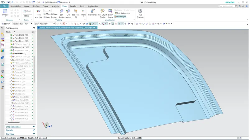
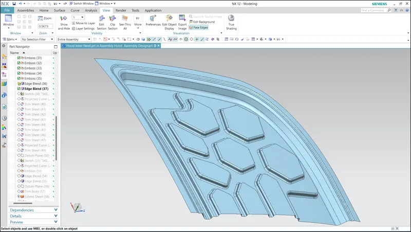
Embosse Cut:
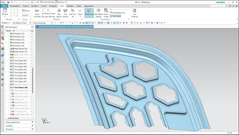
Mastic Data:
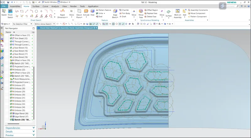
After the creation of embosses, hinge reinforcement was created and it was mirrored along yz plane. The hinge was assembled with hinge reinforcement.
Hinge Embosse:
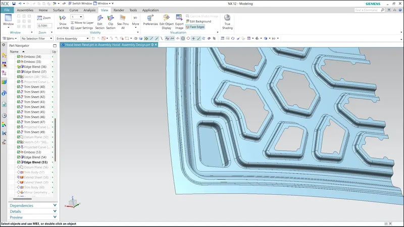
Now, the hinge axis was created by joining the hinges using the line. a circle was drawn in the middle of the hinge axis. A line is drawn tangent to the circle. A line was drawn from the centre of the circle to the intersection point of the circle and the tangent line. A horizontal line was drawn and provided an angle to the line which connects the intersection point and origin of the circle. with this latch, the trajectory was created. Now, a vertical line was drawn in the middle of the striker and assembled to the tangent line. Then latch reinforcement was created by extracting the face of the latch and it was finally assembled.
Latch Trajectory:
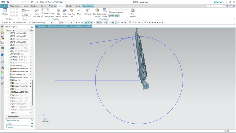
Latch and striker embosse:
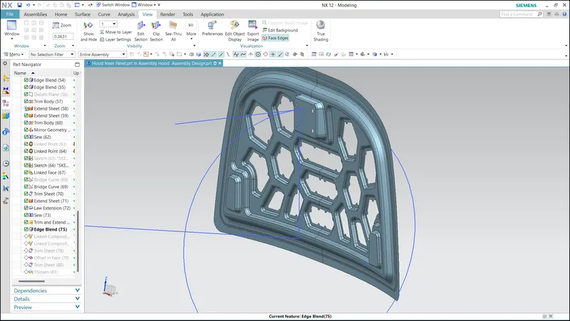
Hemming:
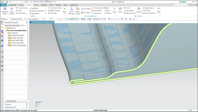
Relief rear section:
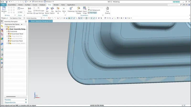
Front Relief:
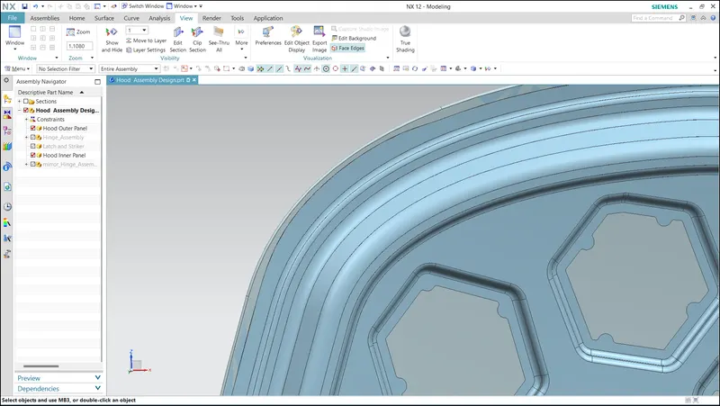
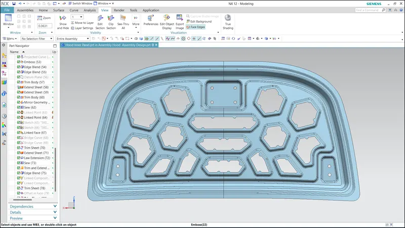
Final Hood Inner Panel View:
5.1 Conclusion:
The hood inner panel was designed by considering all the engineering features and the final hood assembly was created.
Hood Assembly: