Hood design-Week 2
BIW HOOD DESIGN ASSEMBLY:
WHAT IS BIW?
That stage in automotive design or automobile manufacturing in which the car body sheet metal components are assembled by any means like welding, riveting or bolting, etc. is called BIW (Body In White).
Moving parts such as Door, Hood, Trunk Lid, Front Fender, and the components (chassis, motor) and trim (windshields, seats, upholstery, electronics, etc.) are added in a later stage.
PARTS OF BIW:
1. Under Body: It is the base of BIW, it consists of sub-assembly of the engine room, rear floor, and chassis.
2. Upper Body: It is the composition of Body Side L/R, Roof Panel, Cowl & Dash, front fender, rear fender, all pillars.
3. Main Body: The main body is the assembly of the Under Body and Upper Body.
4. Closures: All Doors, Bonnet(Hood), Deck lids are called closures.
WHAT IS A HOOD?
A car hood, also referred to as a “bonnet” in some countries, is the hinged cover that rests over the engine bay of a front-engine vehicle. The car hood protects the engine and connected parts from the elements while providing easy access for repairs and maintenance.
A concealed latch is typically used to lock the hood in place while driving. A release for the mechanism can be accessed from the dash below the steering wheel. On race cars and vehicles with an aftermarket hood, exposed pins may be used to secure the car hood.
Hoods sometimes contain a hood scoop or a power bulge to allow for greater engine capacity and airflow to increase the car’s performance output.
HOOD COMPONENTS:
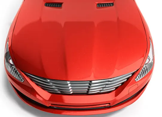
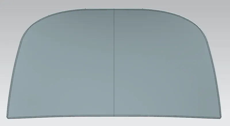
1. Outer Panel: It is panel which provide the aesthetic appeal to the hood and in turn to the vehicle. (as illlustrated below)
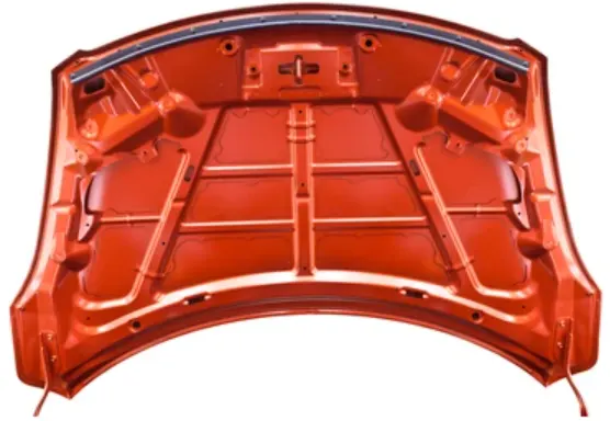
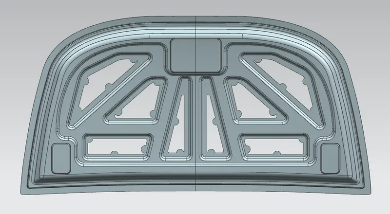
2. Inner Panel: Its main function is to provide the required strength to the hood structure.
It is the main area of focus for a design engineer as maximum required tests and benchmark that are required for an hood to achieve the market standard for passenger vehicle is instilled in it by an design engineer.
Inner panel should comply with following:
- Design should be so that during frontal crash the forces should be diverted outside to the A-pillars and not into the cabin.
- Design should be so that during crash the energy should be absorb by the hood.
(as illlustrated below)
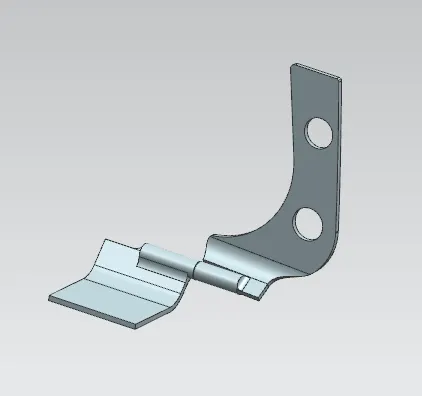
3. Hinge: It provides the desired constraint motion while opening/closing of hood. (as illlustrated below)
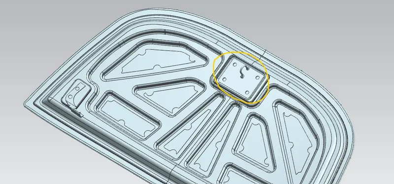
4. Striker:The striker is the part by which the hood is locked into the main body or front bumper. (as illlustrated below)
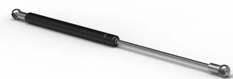
5. Support Rod/Gas stays: These are provided as mechanism which support the weight of the hood when opened.
- Support Rod are used for general purpose vehicle specially in vehicles which does not have large size and have less power engines. (as illlustrated below)
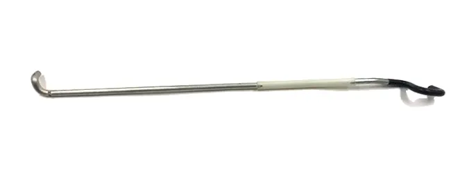
- Gas stays are used for heavy vehicles like SUV's as weight of hood is high for them.
Gas stays are used also in performance vehicles as due to excessive power produced by its engine it also produces more heat hence it is consider safe for using gas stays as a lifting and weight supporting mechanism. (as illlustrated below)
DESIGN CONSIDERATIONS IN HOOD DESIGN:
Maximum Opening Angle of the hood: It depends upon the demographics for the region the hood is being designed.
Support Mechanism to be used: Support rod or Gas stays, depending upon the requirement and functional necessity either is decided.
NVH reduction: For reducing the Noise, Vibration and harshness generally stiffner pad or Mastic seals are used between hood inner panel and outer panel.
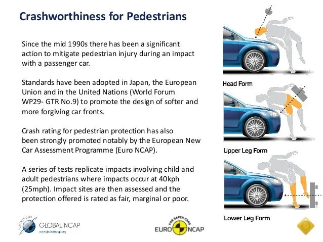
Pedestrian safety rules: The hood of most vehicles is usually fabricated from sheet metal, which is a compliant energy absorbing structure which poses a comparatively small threat.
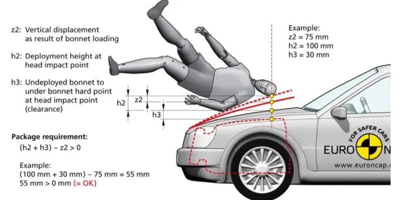
Most serious head injuries occur when there is insufficient clearance between the hood and the stiff underlying engine components.
A gap of approximately 10 cm is usually enough to allow the pedestrian’s head to have a controlled decelaration and a significantly reduced risk of death.
While the lower limb is the most commonly injured body region, most pedestrian fatalities are caused by head injuries.
EuroNCAP norms:
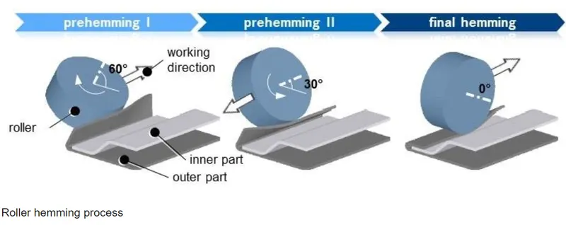
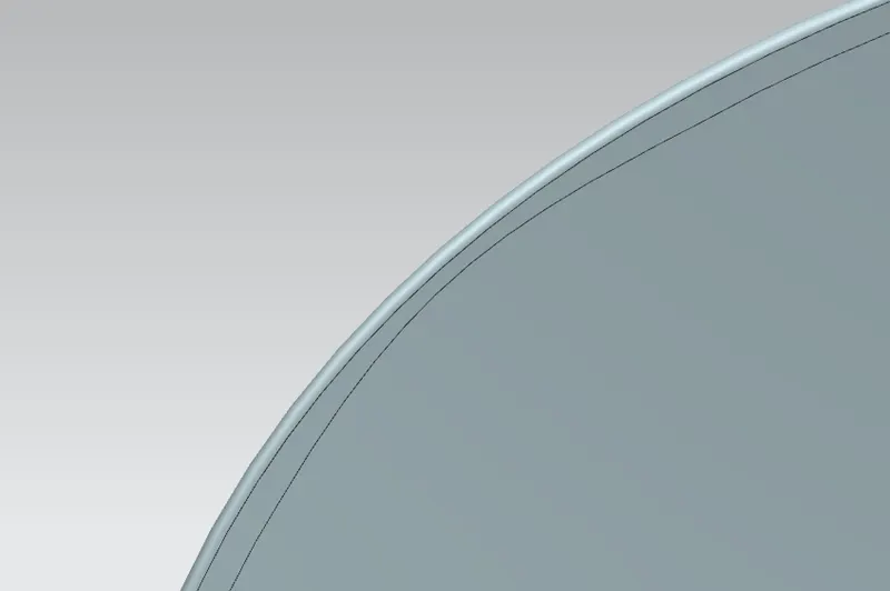
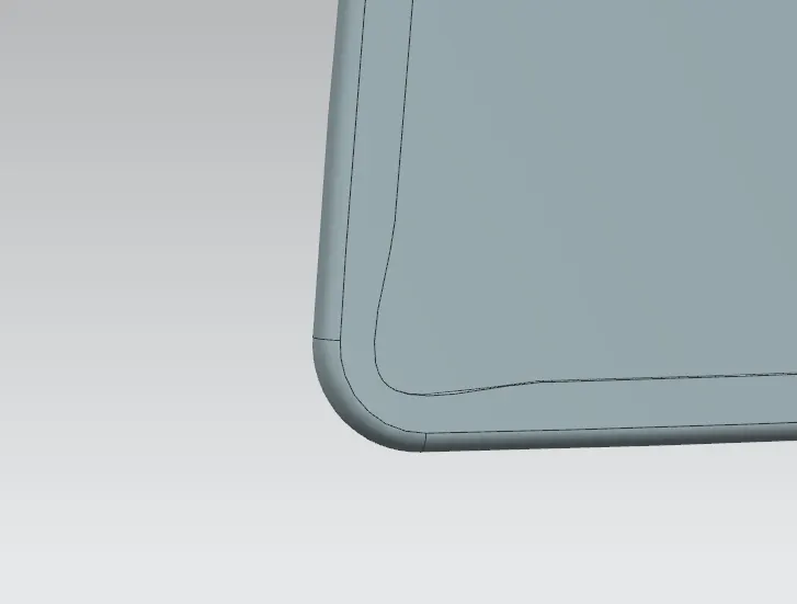
RELIEFS: These are provided to the component in order to remove any stresses developed in sharp corners that takes place during the hemming process by rolling.
Front Relief in Hood:
Rear Reliefs in Hood:
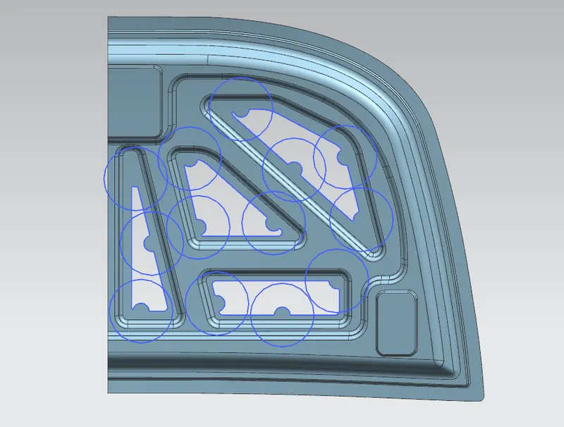
MASTIC SEALS: These are used in hood design for reducing NVH (i.e. Noise, Vibration & harshness) levels.
For mastic seals to work properly, the gap between outer & panel should not exceed by 5mm.
Single mastic seal provide NVH protection in around diameter of 80mm area, therefore the placements is done such that all the circles drawn (as shown in the figure below) should covers the maximum surface area.
SHEET METAL MANUFACTURING PROCESSES:
DEEP DRAWING:
The deep drawing process is a forming process which occurs under a combination of tensile and compressive conditions.
A flat sheet metal blank is formed into a hollow body open on one side or a hollow body is formed into a hollow body with a smaller cross-section.
In the automotive industry, deep drawing is usually carried out using rigid tools.
The figure illustrates the deep drawing process.
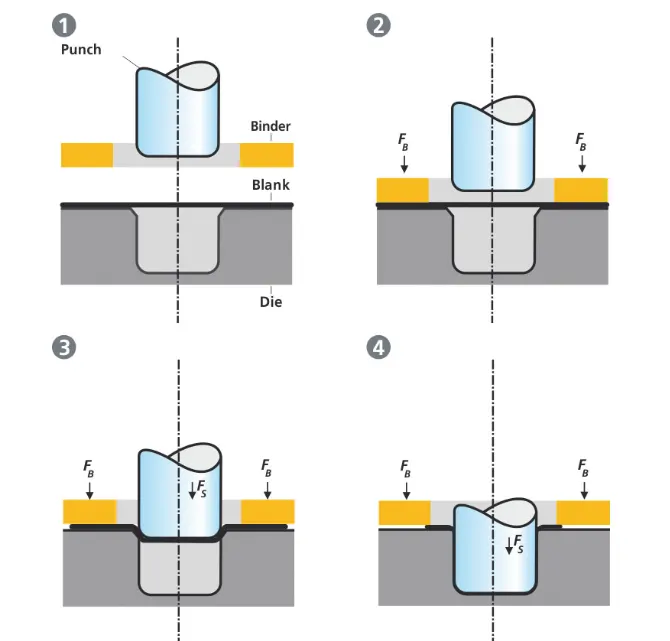
The rigid tools consist of a punch, die and binder. In deep drawing, the plate holder closes after the metal sheet blank has been inserted.
Next the sheet is clamped between the die and the binder. This process slows down the flow of the sheet while it is being drawn and thereby prevents wrinkles from forming under the binder. The punch stretches the sheet over the die radius and forms it in the die. The amount of punch force necessary for forming is thereby continually increased up to the lower dead center of the punch.
Whereas in pure deep drawing there is no reduction of sheet metal thickness, forming is achieved in stretch forming purely as a result of a decrease in sheet metal thickness. Stretch forming is extensively used for the forming of only slightly curved parts with low depth of draw (e.g. roofs, doors).
When drawing complex car body parts in practice, there is usually a combination of stretch and deep drawing involved. It is necessary that the sheet metal is stretched as well as possible without reaching the material’s limits (e.g. splits, wrinkles).
There are approximately 300 to 400 sheet metal parts which fit together to form the body of a car. In order to manufacture high quality sheet metal parts optimally for their particular use, specialized software simulates the complete deep drawing process.
STAMPING:
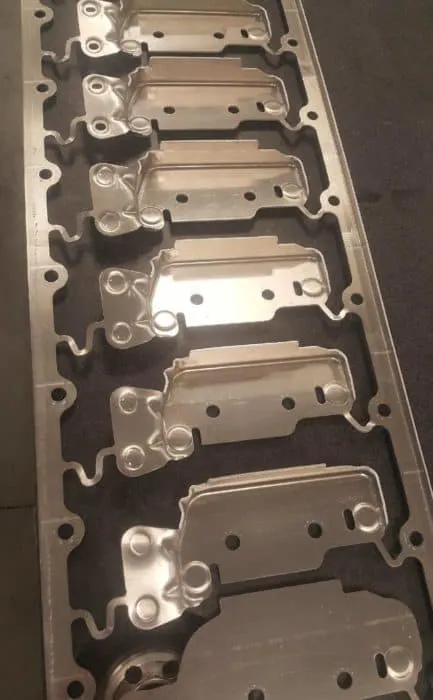
The process of turning sheets of metal into a useful part or component is called sheet metal stamping. The metal is fed into a press, where the stamping tool, also known as a die, creates the desired shape. The die is pressed into or through the metal with tremendous force. The force used in the process is measured in tons.
Except for some specialized processes, sheet metal stamping doesn’t use heat. Instead, it is done with a cold-forming technique. Even though no heat is used, the part can come out hot because of the friction that’s created between the metal and the die from the force of the press.
ADDITIONAL SHEET METAL OPERATIONS FOR HOOD MANUFACTURING:
EMBOSSING:
Sheet metal embossing is a Stamping process for producing raised or sunken designs or relief in sheet metal. This process can be made by means of matched male and female roller dies, or by passing sheet or a strip of metal between rolls of the desired pattern.
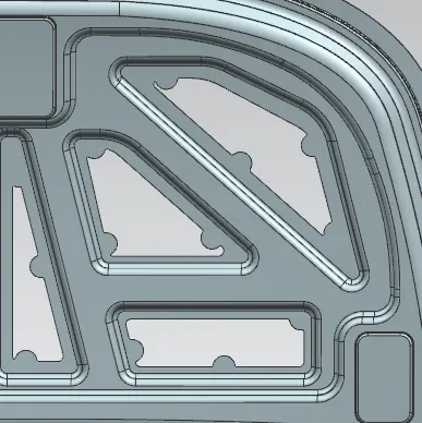
Metal sheet is drawn through the male and female roller dies, producing a pattern or design on the metal sheet. Depending on the roller dies used, different patterns can be produced on the metal sheet.
The pressure and a combination of heat actually "irons" while raising the level of the image higher than the substrate to make it smooth.
HEMMING:
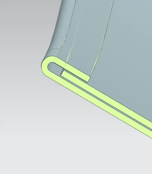
Hemming is a sheet metal forming process in which sheets are joined by bending it usually to 180°. Automotive body panels and automotive parts such as deck-lids, trunk-lids, doors, hoods and tailgates are formed by hemming process.