Hood design-Week 2
HOOD DESIGN ( Automotive sheet metal design using NX CAD)
Introduction:
The hood or bonnet is considered as the frontal BIW enclosure component and is the hinged cover over the engine of four wheeler. Hoods can open to allow access to the engine compartment (or trunk on rear-engine and some mid-engine vehicles) for maintenance and repair. In India almost 99% of cars are font wheel drive with a front mounted engine or even if the vehicle is rear wheel drive or 4 wheel drive the engine is always mounted on the frontal area of the cars. Hood not only adds up to an aesthetic look of a car but also is a major critical component for design and manufacturing
Frontal area and hood design plays major roles in following areas:
A) Aerodynamic Drag reduction ( For increasing efficiency of vehicle)
B) Crashworthiness safety
In design of hood it should meet some specific conditions that satisfies the manufacturing requirements ,functional requirements as well as EURO NCAP standards like:
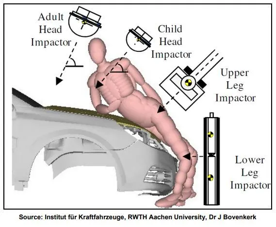
- Load transfer for pedestrian safety during collison
- Wrap Around Distance
- Hood head zone fo lock striker considering average heights of adults and children
- Opening & closing Angle of hood
- NVH (Noise Vibration Harshness)
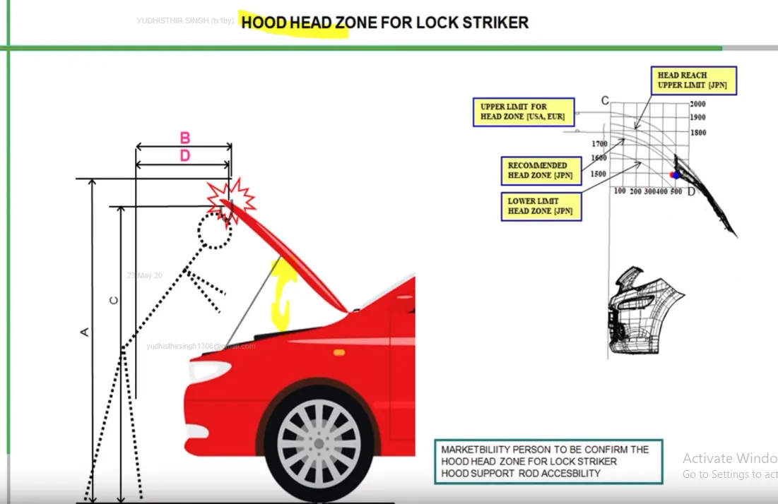
when we open hood there has to be some angle to it’s opening. So that range or angle depends on the average height of person of that particular country. So, it varies from one country to other . Benchmarking person has to confirm the hood head zone for Lock & striker and hood support rod accessibility.
It is important to avoid head injury which may happen through latch and Striker. So, the angle between hood’s rest position or when it is closed totally to angle up to which it will open is important to calculate. This angle varies for different region and this is important to find out.
Here in India its upper limit will be less compared to other European countries and America.
Euro - NCAP ( The European New Car Assessment Programme )
They are the authority who perform experiments and prepare reports based on it and give crashworthiness ratings on how safer the car is for the pedestrians based on the crash tests performed by them. If the car gets high Euro NCap ratings then the car is very much safer for the pedestrians and also becomes a very good selling point in the market. Such as cars in India like TATA nexon are given 5 stars ratings for safety and is very popular in market.
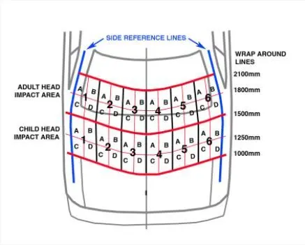
To improve Euro N-Cap Ratings we can start removing materials inside the hood to make it more softer so that, the person when collides with the car will hit the empty area which will have less impact on him.In some case small deformable brackets are given inside fender assembly to improve green zones shown in figure below and eventually to achieve better ratings.
Materials used for manufacturing hood:
Hoods are usually made out of the same material as the rest of the body parts. This may include steel, aluminium, fiberglass or carbon fibre. However, some aftermarket companies produce replacements for steel hoods in fiberglass or carbon fibre to make the vehicle light weight and more strong but carbon fiber is usually very expensive . In most of the vehicle hood is designed from stainless steel or aluminium
Types of Hood:
There are two major types of hoods
1) Inlaid hood
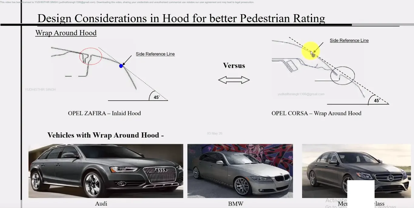
It is lightest among all types of hoods. But it is easily subjected to border defects and body unevenness during manufacturing.There is a gap between the hood and the car body Here the end point or the side reference line of the car lies on the fender , which uses more damge to the pedestrians and hence affecting their Euro-NCap ratings
2) Wrap around hood
As name itself says it wraps around the car body. It can mask the geometrical defects and provide adequate stiffness. It is relatively safer than other types as it provides more safer areas for the pedestrian during impact.
When endpoint of car lies on hood then it is called wraparound hood. Wrap Around Distance (WAD) is the trace of the points received on the front structure when one end of flexible tape of required length held at ground level and other end in contact with the front structure.
Side Reference Line - It means the trace of the highest contact point between straight edge inclined at an angle of 45 degree and side of the vehicle.
Hoods can also be classified based on the Hood stay types :
1) Support Rod Hood Type
A hood stay is an apparatus for an engine room of a car , which can safely keep an engine hood in an open state if an external force is abruptly generated due to vibration, wind & can facilitate an opening/closing operation of the engine hood.
It Is the basic and most commonly used support for the hood in low cost and mid range cars, Since it is cost effective.
Also there are restrictions to the design of the hood stay . The maximum distance a rod can be bent is less than 35mm. As shown in the below figure and also the hood support rod should be fixed at the opposite end of the battery compartment enabling the ease of operation near the battery area.
Gromets are used to fix the support rod.
2) Gas Stay Hood Type
These type of Hood Support does not require much of Man power and is very useful when the weight of the hood is more heavy to lift. This is usually seen in bigger cars like suv's. These gas stays are provided in the back door to all car segements these days.
It has two ends where one end is fixed to engine compartment and the other to the hood itself. The length C & D is kept constant and only the (B-A) length is varied. We could say that if the length of the Hood increases , (B-A) length also increses.
Stud ball is used to fix the gas stay support.
SHEET METAL OPERATIONS
1. Blanking & Piercing -
Blanking and piercing are shearing processes in which a punch and die are used to produce parts from coil or sheet stock. Blanking produces the outside features of the component, while piercing produces internal holes or shapes. The web is created after multiple components have been produced and is considered scrap material . In blanking, the piece is cut off from the sheet, and it becomes a finished part. In piercing, the cutout portion is scrap which gets disposed off while the product part travels on through the remainder of the die. The terminology is different here, though both processes are basically the same and therefore belong to the same category, which is the process of metal cutting.
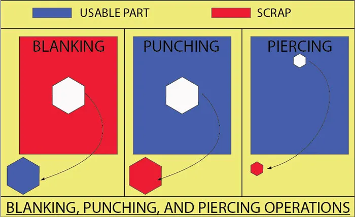
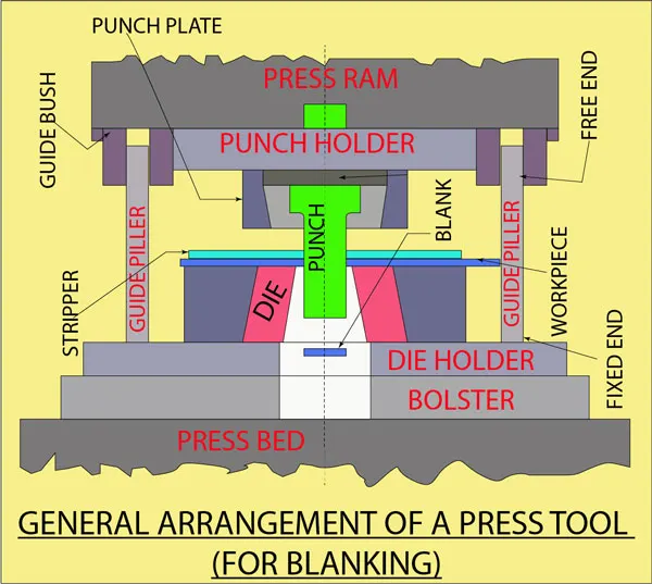
When we do punching, a piece of metal is removed from the inside of the part, and when we do blanking, the metal around the part is removed.
2) Deep drawing
Deep drawing is a manufacturing process that is used extensively in the forming of sheet metal into cup or box like structures. Pots and pans for cooking, containers, sinks, automobile parts, such as panels and gas tanks, are among a few of the items manufactured by sheet metal deep drawing. This process is sometimes called drawing and is not to be confused with the bulk deformation process of drawing discussed earlier. A basic deep drawing operation could be the forming of a flat sheet into a three dimensional cup, or a box. The shape of a deep drawn part is not limited to a circle or square, more complex contours are possible. However, as the complexity goes up, the manufacturing difficulties increase rapidly.
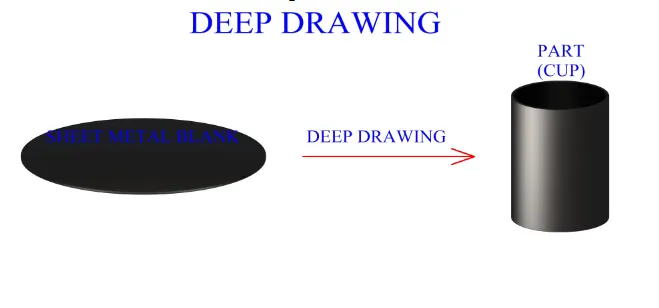
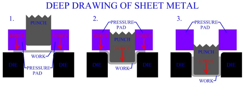
Deep drawing of sheet metal is performed with a punch and die. The punch is the desired shape of the base of the part, once drawn. The die cavity matches the punch and is a little wider to allow for its passage, as well as clearance.
3) Embossing:
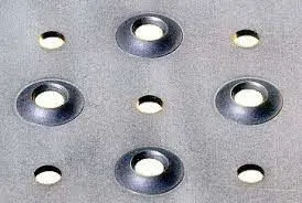
Sheet metal embossing is a stamping process for producing raised or sunken designs or relief in sheet metal. This process can be made by means of matched male and female roller dies or by passing sheet or a strip of metal between rolls of the desired pattern. The metal sheet embossing operation is commonly accomplished with a combination of heat and pressure on the sheet metal, depending on what type of embossing is required. Theoretically, with any of these procedures, the metal thickness is changed in its composition.
4. Hemming -
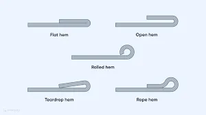
Hemming is a sheet metal forming process in which sheets are joined by bending it to 180°. Automotive body panels and automotive parts such as deck-lids, trunk-lids, doors, hoods and tailgates are formed by hemming process. In this process, usually a sheet is bent with the help of inner sheet in three different stages
Design Methodology:
Input Given:
Class A surface: It is one of the most important input in automobile industry specially in surface and sheet metal design and is also one of the stages of design life cycle usually class A surfaces are created in Autodesk Alias for sketching concept modelling and visualization and then New product development in cad software is carried out. Class A is an aesthetic surface developed by a styler.
Master Section:
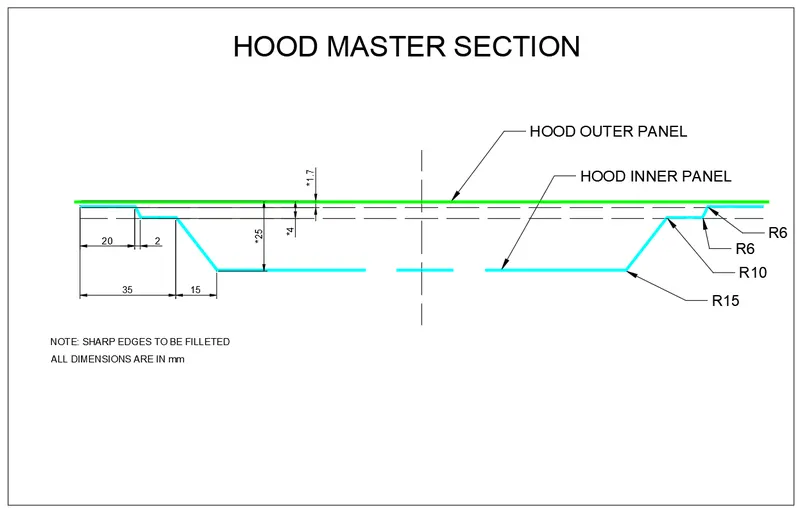
Hood Design is comprised of following components like:
1) Hood Outer panel
2) Hood Inner Panel
3) Striker
4) Hinges
5) Reinforcements
Data provided:
Hood Thickness Information
- Outer Panel Thickness = 0.75mm
- Inner Panel Thickness = 0.75mm
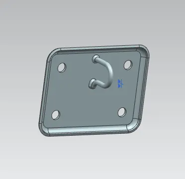
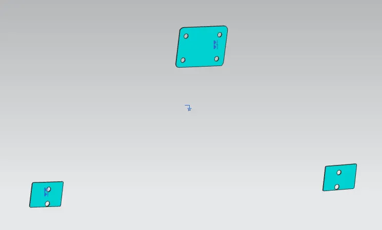
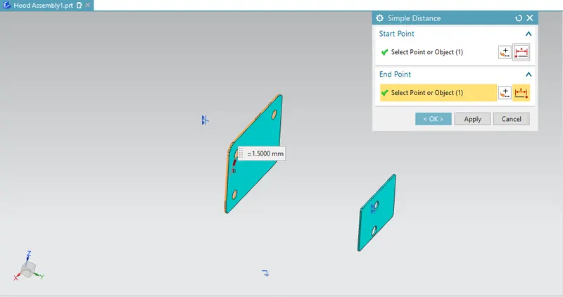
- Reinforcement Thickness = 1.5mm
Tooling Axis :It is the direction in which the mold or core cavity opens to eject the part or the direction in which sheet metal part is ejected out clearing the draft angle .For sheet metal components the draft angle must be greater than 7 degrees.There are multiple methods for creation of tooling axis.
For tooling axis creation in this design
1) we have to create two points on the end edges after trimming half the body
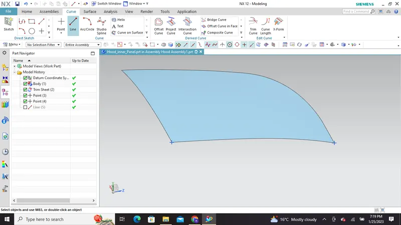
2) we need to create a line in between these two points
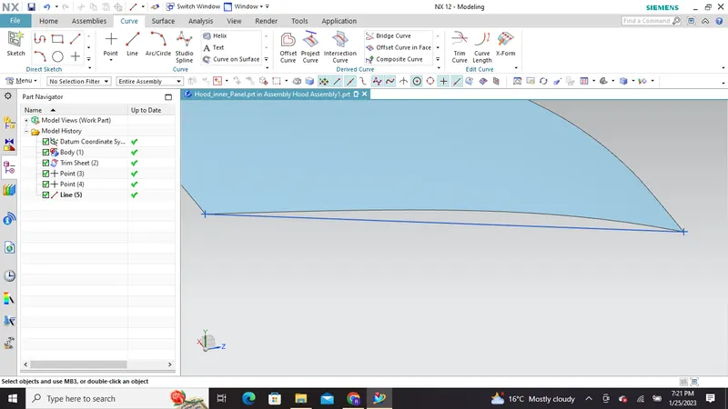
3) We have to create a line with a point( the point is at the mid center of the line ) and direction same as catia software , As we have a point and a line we can give constraint to it like curve( curve means the line) on point or line perpendicular to that point.
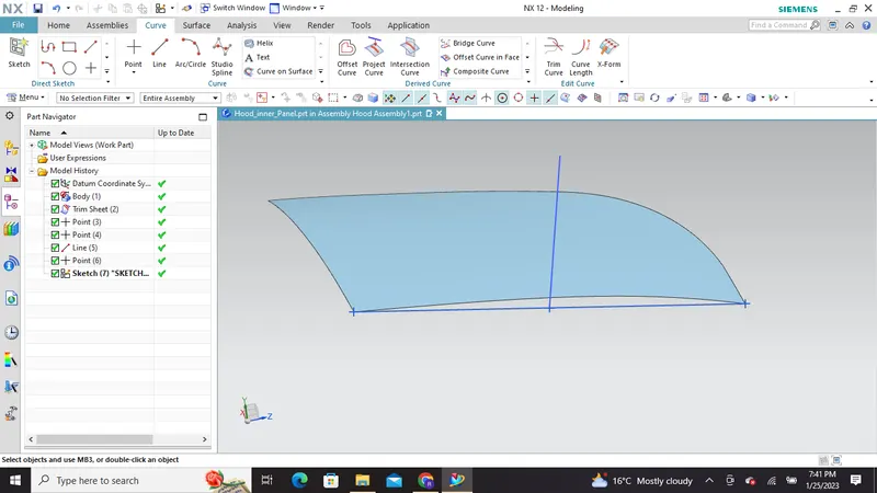
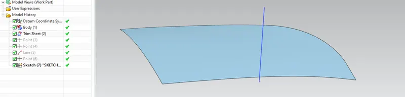
In the final step we can hide all the points and line which we used to create tooling axis and then we can assign color to the tooling axis and hide it also for the time being.
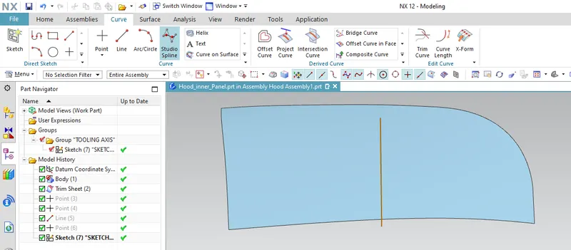
As we used to use publications in catia for publishing any feature which was easy to access so here i have made a new group with name tooling axis and aligned the tooling axis sketch with that which made it easy accessable for hiding and unhiding whenever required.
INNER PANEL CREATION:
We will offset parent surface to 1.7mm , 4mm and 25mm and then see master section and offset curve on face 20mm, 22mm, 35mm,50mm respectively
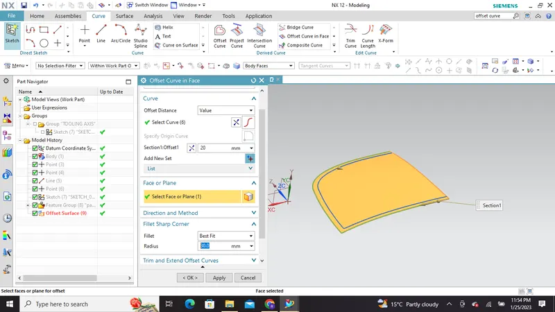
we will use trim sheet to remove the surface not required
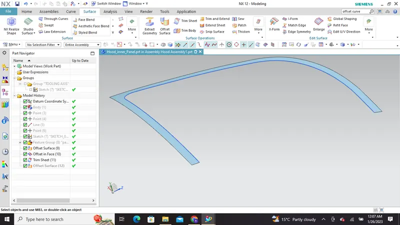
Another offset curve on face of 22 and 35 mm
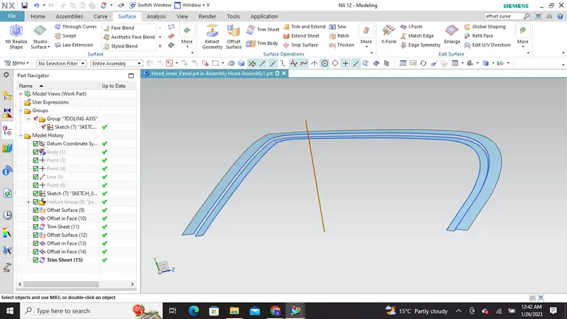
25mm offset with 50mm offset curve on face and finally trim and keep the middle surface as per master section
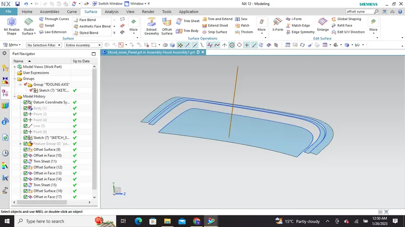
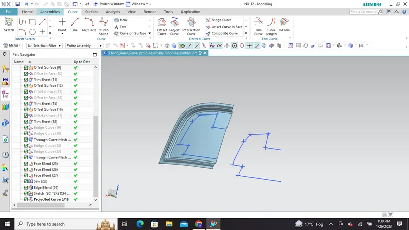
EMBOSSING: WE NEED TO PROJECT SKETCH / CURVE ON THE FACE AND MAKE SURE THERE IS ENOUGH SPACE FOR STRIKER AND HINGE ASSEMBLY AND SKETCHES SHOULD NOT HAVE SHARP CORNERS
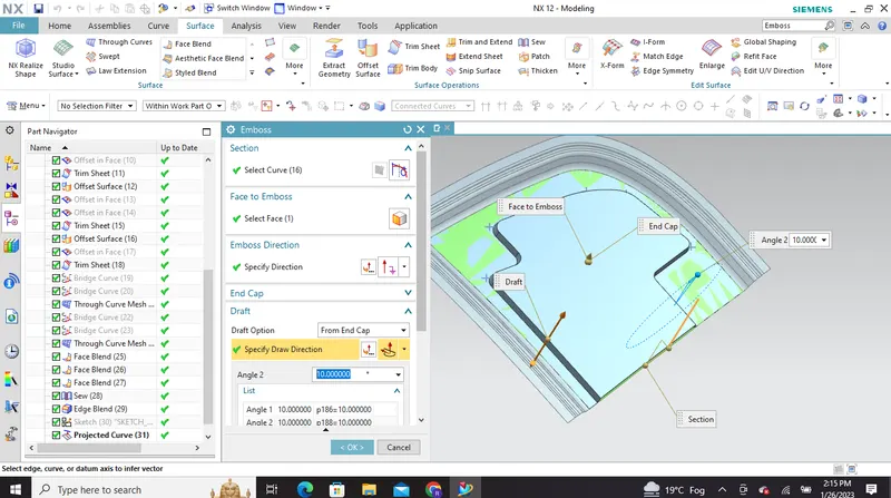
While giving emboss we must make sure draft angle is more than 7 degrees and also we must specify draw direction as our tooling axis.
All embosses creation with Mastic points
Hood has a large surface area and hemming can only be provided through its boundary. Other joining techniques like welding, riveting etc are prohibited because they leave marks on the outer panel which can affect its aesthetic appearance. So, mastic sealants are used to stick the inner surfaces of outer panel and inner panel. Mastic sealants are elastic compound that behave like rubber. It is applied between the inner and outer panels at specified spots. Each spot of mastic sealants has its effect around a circular region of 80mm diameter. Thus, the mastic points are arranged in such a way that it covers the areas away from the hemming which are more vulnerable to vibrate.
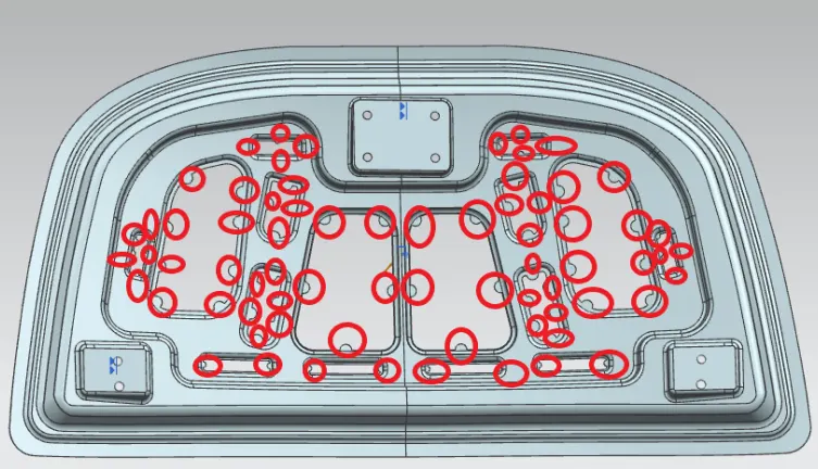
Mastic Points
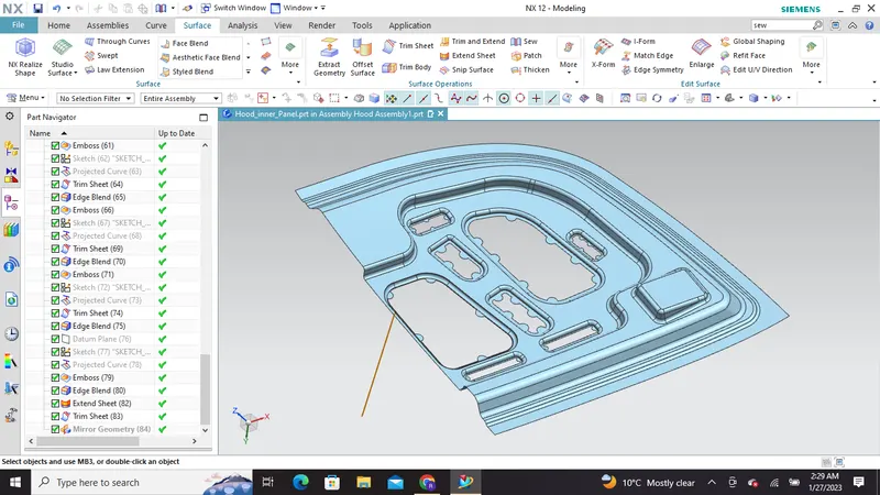
Embossed Faces
Then we need to mirror geometry and sew the mirrored geometry surface together if there is some patches gaps or overlaps then we need to extend sheet and then trim sheet with respect to plane
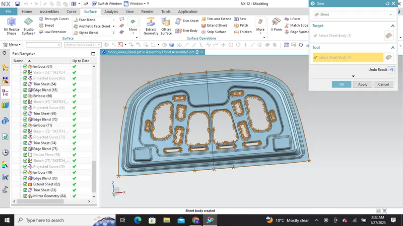
We have to sew body with no boundaries in between
Creating Trajectory : For the proper opening & closing of the hood, the striker should be perpendicular to the trajectory of the hood. Firstly the hinge is positioned and an axis is drawn.The Trajectory is derived from the hinge axis and the centre distance from the striker. It is denoted as a circle as shown below
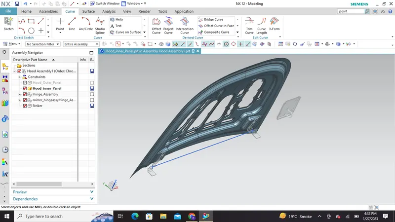
we will create 3d points and line on hinges first which will be considered as hinge axis
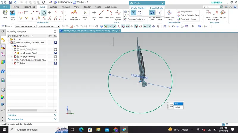
we will create a circle from the same datum plane which we used to mirror or trim sheet into half and the point will be one of the visible point on hinge and then create a tangent to it
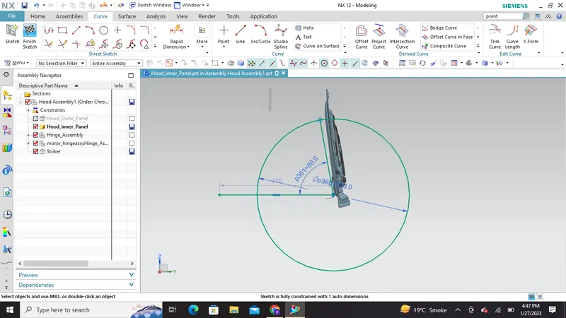
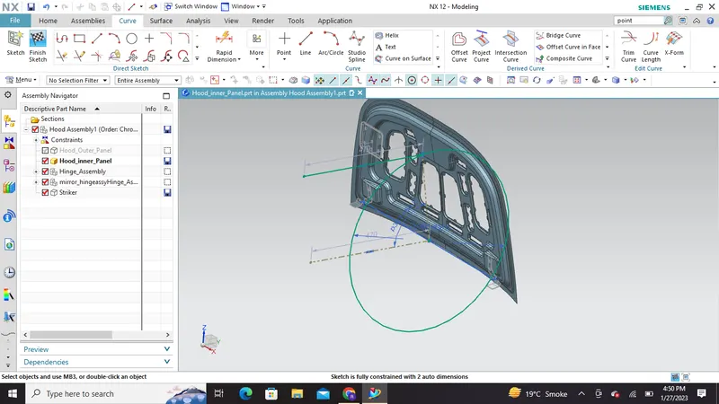
we will turn other lines to reference elements and this will be the latch and striker trajectory
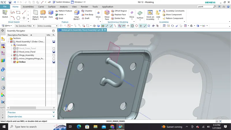
in striker we will create a datum plane on curve and create a sketch to draw a center line for align purpose
Now we will actiavte the assembly (The trajectory and reference axis would not have been visible after activating assembly so we can follow two methods for that
1) reference sets and then replace reference sets
2) featured group and then hide it later
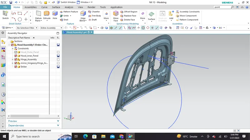
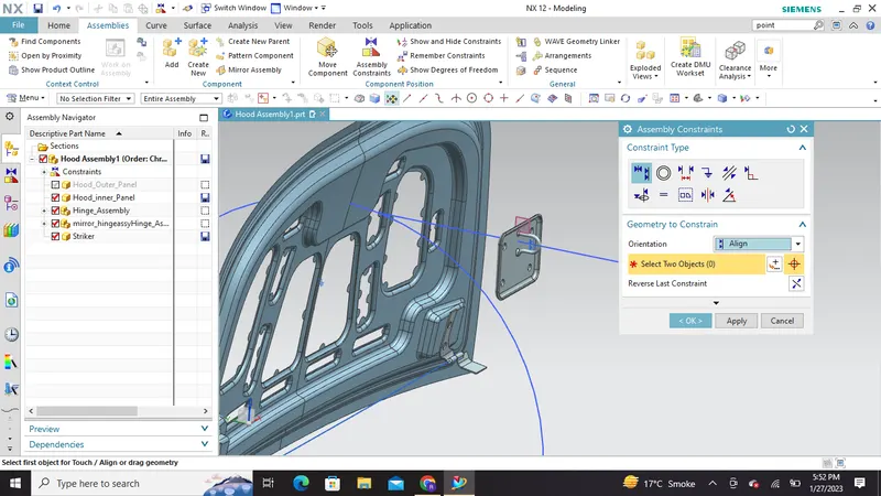
Align constraint
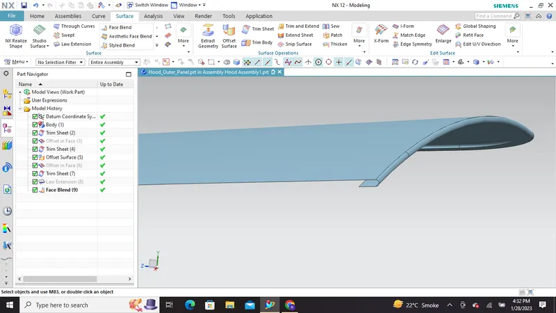
Outer Panel creation :
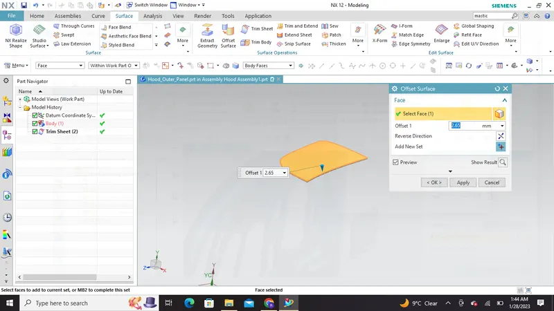
Outer panel =3t +2x0.2= 2.65mm will be the first offset
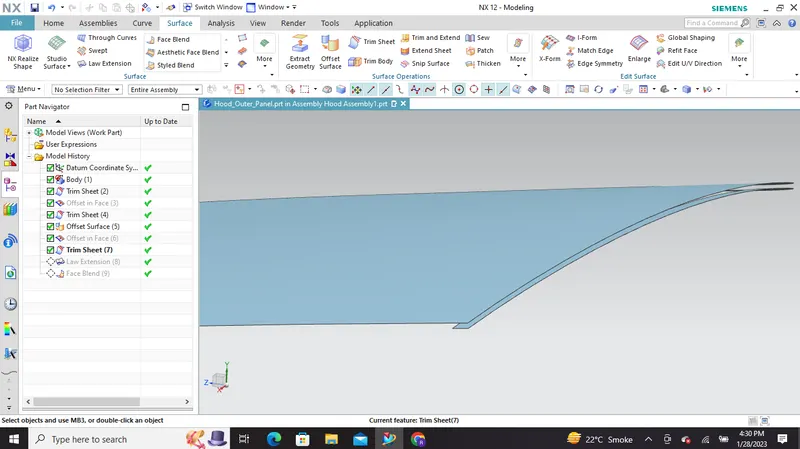
Then law extension command between the offset surfaces is applied
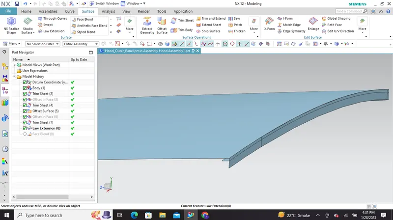
Finally hemming done with three face blend
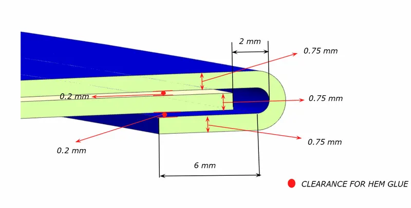
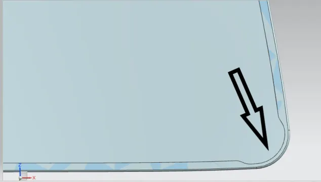
Corner reliefs : Provided in the hemming area,These reliefs are provided on the surfaces to avoid Springback situations. The springback occurs when the rollers are made to roll on the surfaces to join the outer and inner hood , the hood surface at the corners tends to come back or spring back to its primary position due to lack of pressure of the rollers on the surface. Hence, when reliefs are provided then there is no need for the rollers to pass completely near the corners.
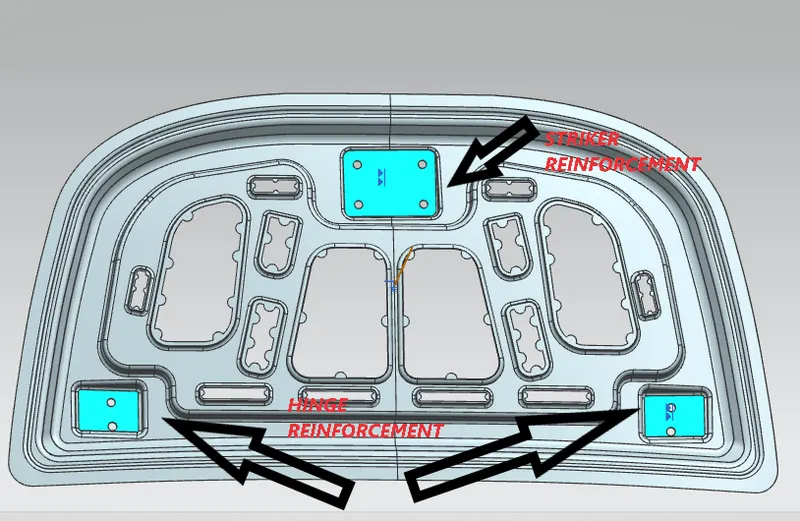
Reinforcements : Reinforcement are provided mainly in hinge and latch regions. When hinge and latch assemblies are attached to inner panel, strength of that area reduces locally so we add some additional material to increase the strength of the area locally. Thickness of reinforcement material is provided according to the design requirements. In this project, 1.5mm thickness has been given to both latch and hinge reinforcement.
Assembly in NX CAD:
Assembly in any cad software can be followed by two approaches such as:
A) Bottom up Assembly : In this type of approach the parts are created individually in part workbench and then are assembled in assembly workbench with the help of geometrical constraints and other features.
B) Top down Assembly : In this type of approach the parts are created inside the assembly workbench by starting the product file and then creation of individual parts is carried out and they can be opened separately in part workbench.
However we can also use both types of assembly combination at a same time if some parts are created while others can be created in assembly workbench.
In this project i have followed Top Down Assembly procedure
Part Tree:
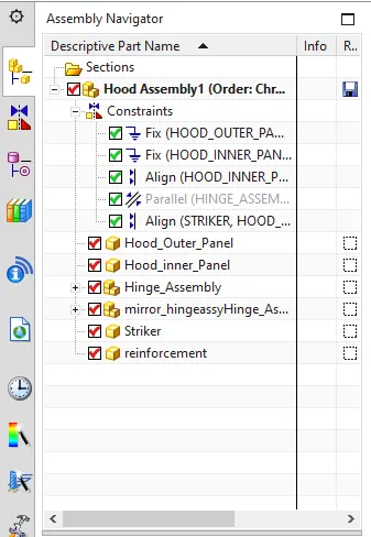
Outer panel
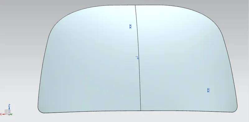
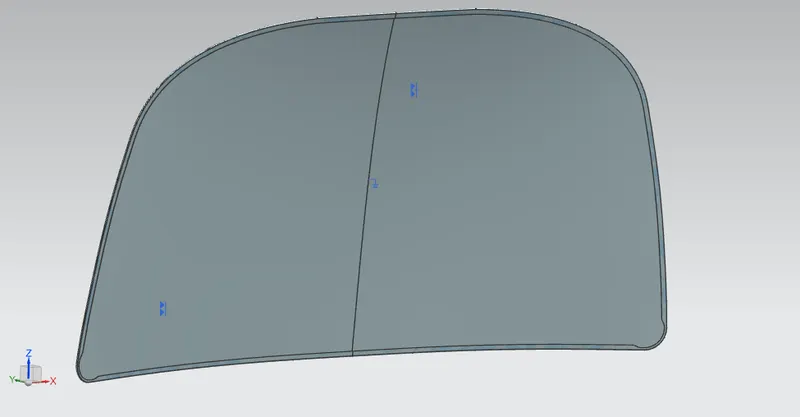
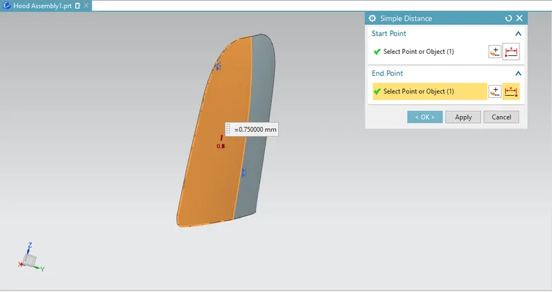
Thickness of 0.75mm
Inner panel :
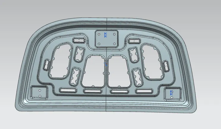
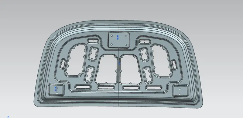
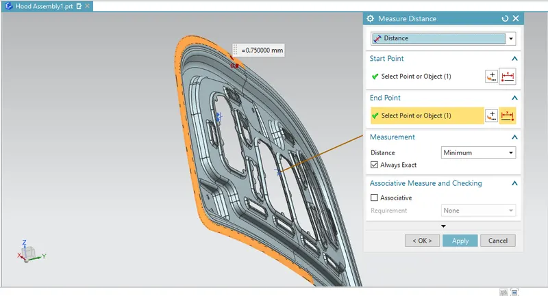
Thickness of 0.75mm
Hinges:
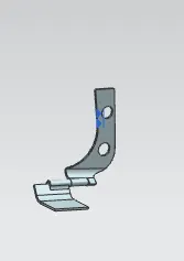
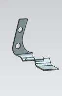
Striker :
Reinforcements:
Thickness of 1.5mm
Different views of the Hood in various orientations :
1) Isometric View:
2) Bottom View
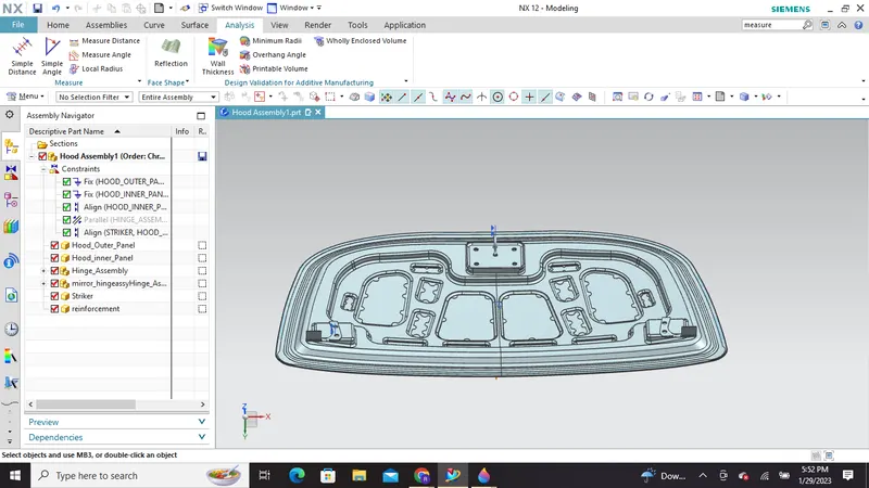
3) Front View
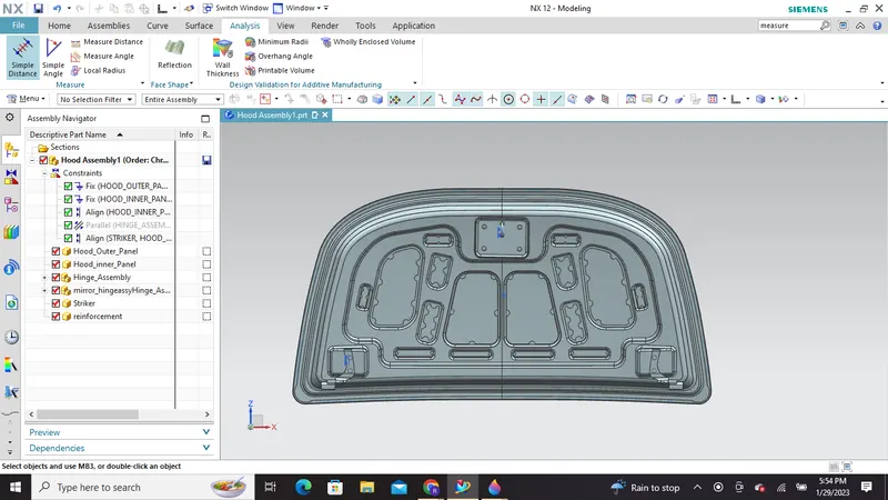
4)Top view
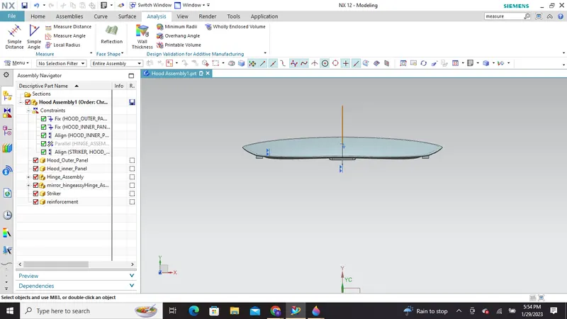
5) Side view
left view
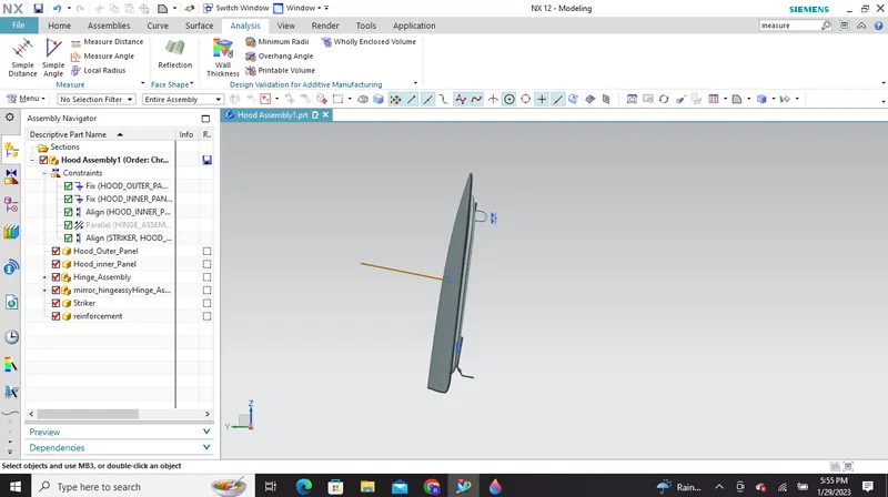
Right view
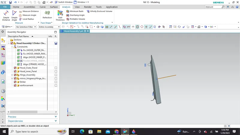
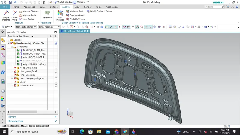
Final Assembly :
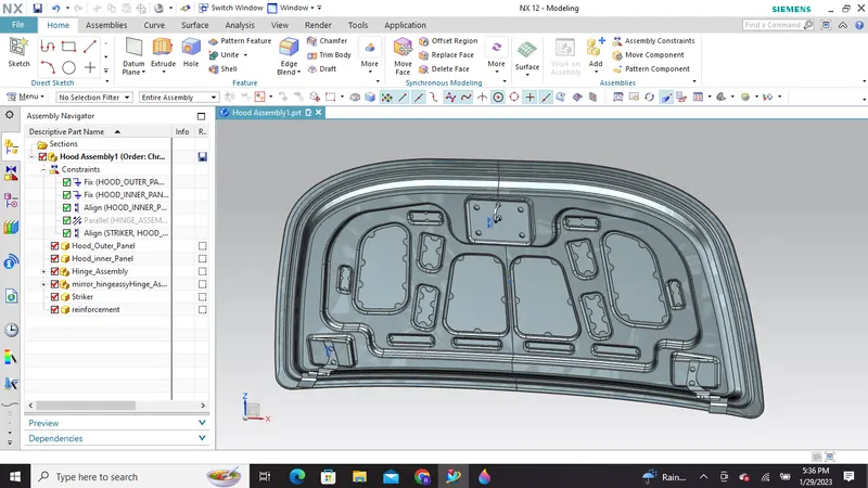
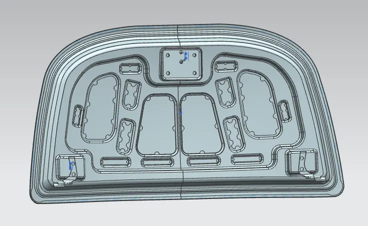
Draft Analysis: Draft is the angle in which the part is tapered to allow it to release or eject.
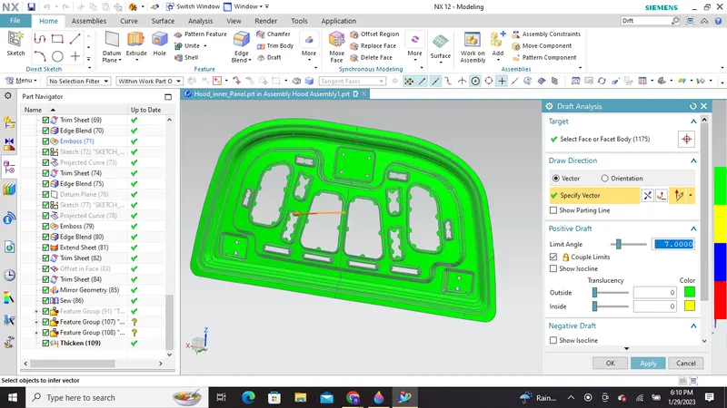
All the embossed faces of inner panel is clearing 7 degrees draft with respect to tooling direction
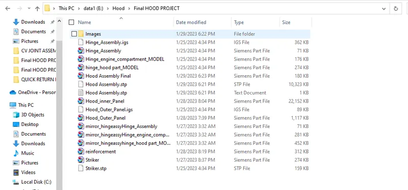
Please find the attached Part and assembly files
# Extract the rar file with name Final Hood Project
# Hood Assembly Final (.prt 180Kb size) is the main assembly file also i have attached the .stp file
Thank You !