Hood design-Week 2
REPORT :
Hood : It is the opening body panel that covers the engine compartment and is simply referred as hood
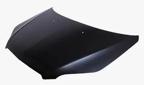
Fig :1
Striker : It is used to lock the hood into the engine compartment .It is shown in the below figure
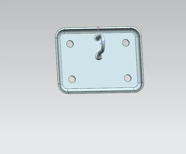
Fig : 2
Hinge Assembly : It is used to open the hood at a particular angle with respect to the engine compartment.It is shown in the below figure
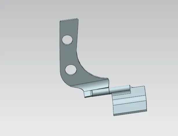
Fig :3
GAS STAY :
Gas stay :It is also a type of hood which covers the engine compartment but the opening and closing of the gas stay is by hydraulic press.
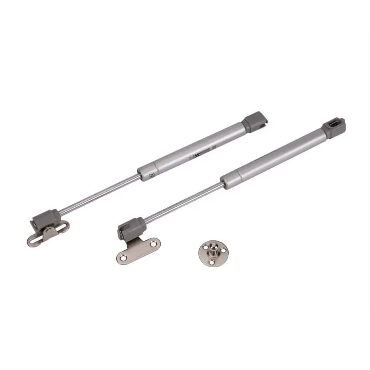
Fig :4
Advantages and Disadvantages of Support Rod and Gas Stay
| Support Rod | Gas Stay |
| The opening and closing human is requried | The opening and closing is done hydraucilly |
| If temp of the engine is more through conduction the rod recives heat energy at this stage if we try to mount or dis mount it will cause burns | No such case in this component |
| Cost of the component is low | Cost of the component is more |
| It is used widely in cheaper cars | It is used mostly in premium cars |
Latch Trajectory :
It is the trajectory of the hood panel when the hood opens while closing the hood panel hood should fit in the engine compartment even if small change in the angle,then the hood panel doesn't fit.The trajectory of the stiker and the panel should be equal to the engine compartment so that the smooth opening and closing of the hood panel will be done.
The Gap is created in the the inner panel of the hood is not for material removal or to reduce the cost of manufacturing,It has the best design parameter that i have known till now.The gap is provided to give maximum safety to the pedistrain if any crash happens so that the impact to the pedistrain will be low.
If the car is travelling at 50 kmph and hit the pedistrain he will survive the crash with out any injuries the reasons are listed below
There are 2 kinds of zones in the designs they are
1.Adult head impact zone : In this zone the safety is from 1700 to 2100 mm
2.Child head impact zone : In this zone the safety is from 1000 to 1700 mm
As shown in the figure the wrap around distance decides wheather the pedistrain will fall under the child head impact zone or the adult head impact zone
Wrap Around Distance :
It is defined as the distance after the crash of the pedistrain the head of the pedistrian will wrap on the hood,The distance between the head impact zone and the ground is called as wrap around distance
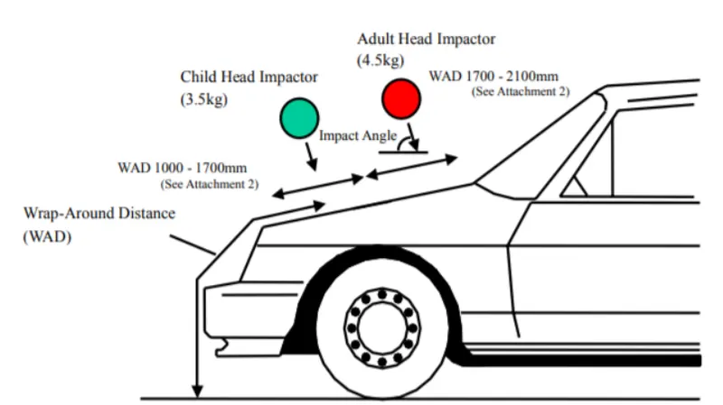
Fig :5
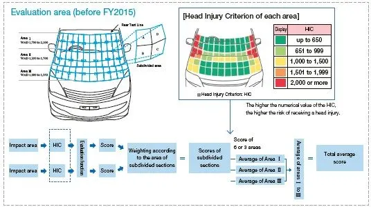
Fig :6
The OEMs are trying to give the maximum safety to the pedistrains by reducing the impact zone in the hood and the reports say that from 2012 to 2020 the impact zone has increased a lot for the pedistrains.
In the above figure if the pedistrian fall on the green colour then he is safe,the OEMs are trying to increase the green color so that the safety of the pedistrain will increase.
Emboss : It is defined has the raised object from the surface
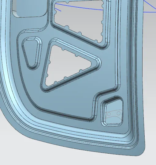
Fig :7
As shown in the figure the height of the slightly more when compared with the bottom most surface the raised part is known has embossed.
The Embosses are created to give the safety to the passengers inside the car if crash happens the velocity is distributed outside the region of the car and shouldnt reach the engine compartment also
Corner Reliefs : These are given at the edges of the outer panel because the hemming is done with the rollers,at the edges the stress concentration is more when compared with the faces the outer panel so to control the stress concentration the corneer reliefs are given
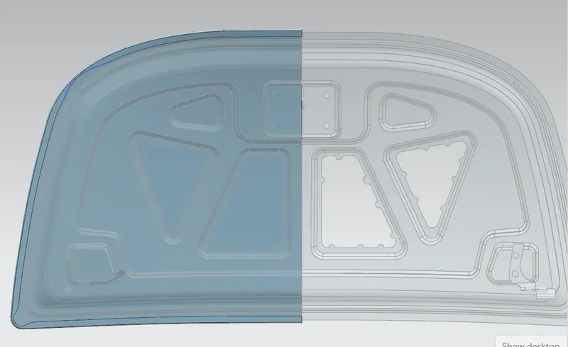
Fig :8
Design Considerations for the Hood
1.Opening and closing of the Hood
2.Mounting and dismounting position of the hood stand
1.Opening and Closing of the Hood :
It is taken has the design consideration for the Hood because for example in the countries like USA the average height of the person is 5.9 to 6 feet up to this the angle is calculated and designed of the height of the person is more and the angle of opening is less and the person cannot see properly the engine compartment and this become a negative for the car and results in decrease of the sales.
2.Mounting and Dismounting position of the Hood Stand :
The Mounting position of the Hood stand is on the hood panel while the dismounting position of the hood stand is on the engine compartment in some of the cars it is mostly on the right side while in some cars it is on the left side while desigining the hood stand it should give maximum space for the engine and all the other accessories that are present inside the engine compartment ultimately the position of the stand and mounting and dismounting of the hood stand should be free to open and shouldnt disturb the function of other components.
Mastic Glue: It is used to join both the inner and outer panel together .
As the joining of the two surfaces with the glue is costlier but still using because the asthetic surface of the car is important if any welding is done on the panel it will effect the aesthetic surface of the car that is why welding is strictly prohibited.
Drafting : It gives an idea wheather the designed component clear the manufacturing that is why the component should be designed in such a way that it should clear manufacturing.
The draft angle should be not more than 7 Deg.
Hemming : It is defined as the bending at the edges to form a round surface is known has hemming.
There are different types hemming they are
1.Open Hem
2.Closed Hem
3.Rolled Hem
4.Tear Drop Hem
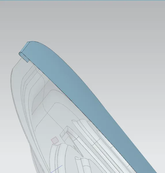
Fig : 9
This is the hemming part that is created from the outer panel by offsetting the outer panel to 3.15 mm by giving the clearence and by considering the thickness of the outer panel 0.75mm and inner panel thickness to 0.75 mm and outer panel 0.75 mm and 0.5 mm for additional thickness
0.75+0.2+0.75+0.2+0.75+0.5 =3.15mm
by using face blend hemming is created and by using mirror geometry mirror the component and sew then the final outer surface is obtained and sew both the components together and thicken it using thicken option.
Procedure For creating the Hood Assembly :
1.Make sure that all the downloaded stp files are in the same file.
2.Load the striker,inner panel,outer panel and the hinge assembly into the assembly workbench.
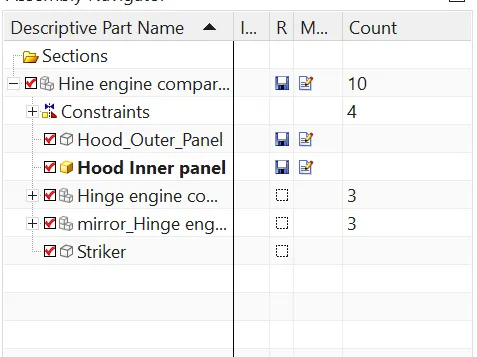
3.By activating the inner panel work on the part as shown in the given master section use the commands trim sheet,offset curve in face,through curves and law extension to obtain the above master sections.
4.After creating the master section make a design for the emboss skectch it on the inner panel create the emboss by using the emboss command up to certian height and also give requried space for the striker and the hinge assembly.
5.Now its time to work on the hinge assembly select the centre point of the hinge assembly and mirror the hinge assembly on to the other part in the other part also select the same point and create the axis by using the line.
6.For the striker select the midpoint by using the datum plane and coincide the striker with the axis of the hinge assembly by using the skecth with assosiative property(if any changes or modifications are given to the hinge assembly in terms or rotation of the hinge or the length the changes are applies to the striker also).
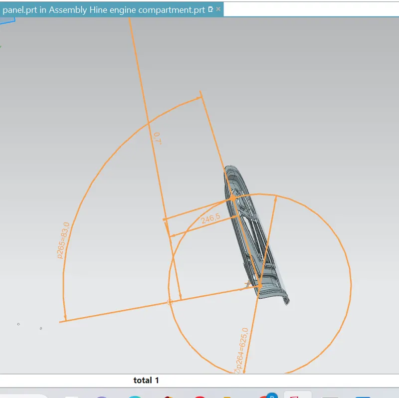
Fig :10
7.Stiker come onto the hood assembly into its position after coincideing with the hinge assembly,extract the front face of the striker with the command using wave geometry linker,and then extend the surface of the extracted face using extend sheet and then using law extension to create the emboss for the striker.
8.In the final step trim and extend the striker emboss and the inner panel.
9.Now perform the hemming operations and give the corner reliefs on the outer panel and mirror and sew and thicken the outer panel.
10.The requried hood assembly is designed as shown in the below figure.
11.Where ever the sharp edges are present ensure to give fillets by using the face blends
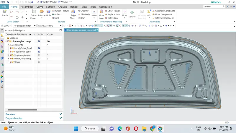
Fig :11
For Opening the files Hine engine compartment is the Hood Assembly
Model Files are
1.Hood Inner Panel
2.Hinge engine compartment
3.Striker
4.Hood_Outer_Panel
5.Mirror_Hinge engine compartment