Hood design-Week 2
HOOD DESIGN
OBJECTIVES-
Design Hood Outer Panel, Inner Panel and the necessary Reinforcements by following the given Master section and design parameters.
SOFTWARE USED-
NX CAD
GIVEN INPUTS-
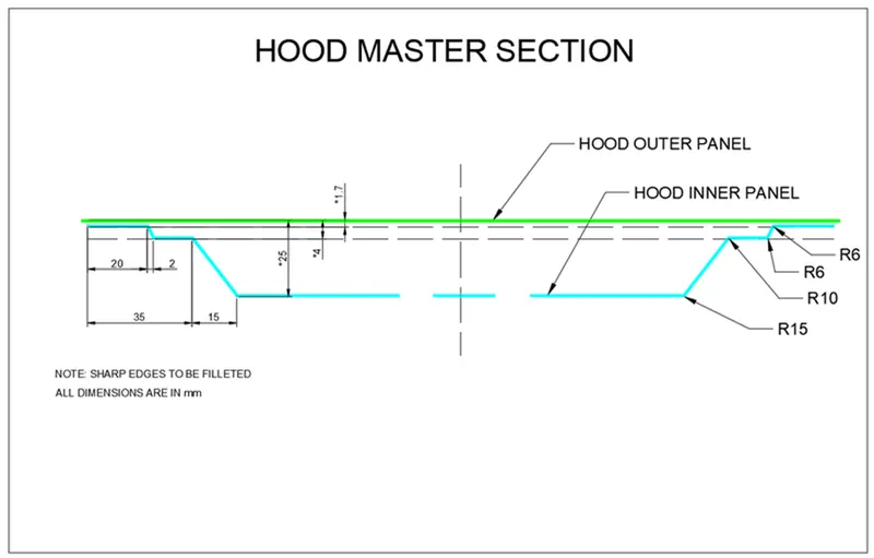
Master section- Master Sections are the guides for design requirements which shapes the component after technical styling of Class A Surfaces.
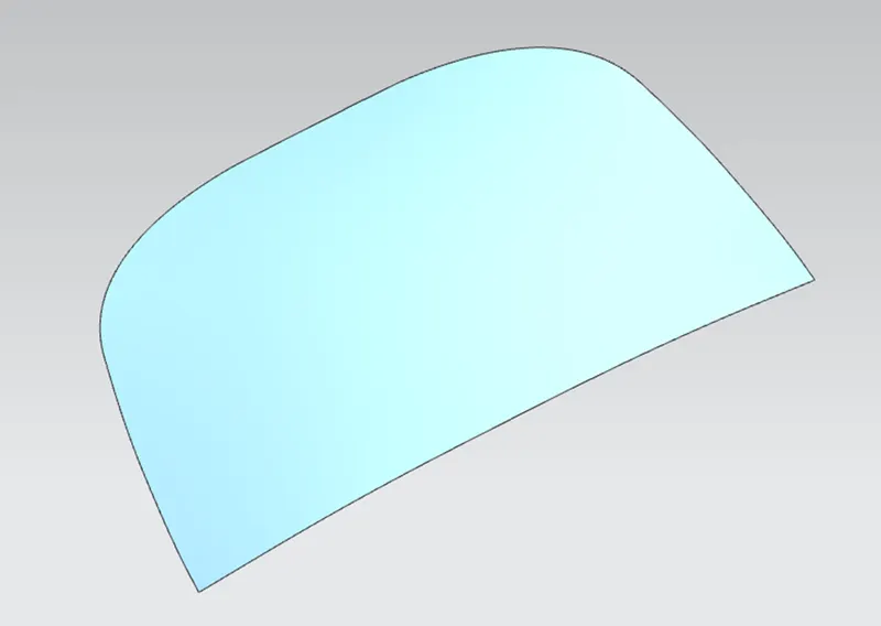
CLASS A SURFACE- Class ‘A’ surfaces are primarily used in the automotive environment and refer to those surfaces which are visible in a product. In other words: A - class surfaces are those aesthetic/free-form surfaces, which are visible to us (interior/exterior), and have an optimal aesthetic shape and high surface quality.
Design parameters-
Hood Thickness Information
Outer Panel Thickness = 0.75mm
Inner Panel Thickness = 0.75mm
Reinforcement Thickness = 1.5mm
INTRODUCTION-
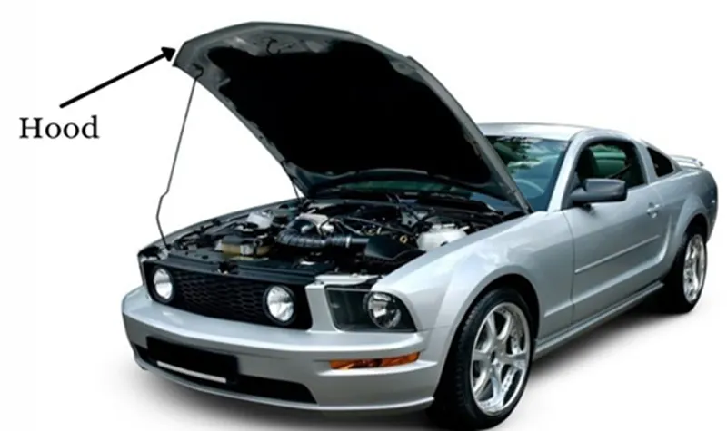
A car hood, also referred to as a “bonnet” in some countries, is the hinged cover that rests over the engine bay of a front-engine vehicle. The car hood protects the engine and connected parts from the elements while providing easy access for repairs and maintenance.
Car hoods are typically constructed from steel and sometimes from aluminum. Aftermarket car hoods may be constructed from various other materials, including carbon fiber, fiberglass, or dry carbon.
A concealed latch is typically used to lock the hood in place while driving. A release for the mechanism can be accessed from the dash below the steering wheel. On race cars and vehicles with an aftermarket hood, exposed pins may be used to secure the car hood.
Hoods sometimes contain a hood scoop or a power bulge to allow for greater engine capacity and airflow to increase the car’s performance output.
DESIGN CONSIDERATION-
- Head clearance zone.
- Opening angle.
- Consideration of Noise vibration harshness.
- Padestrian safety.
- Providing emboss for more strength.
MANUFACTURING PROCESS-
The most important design consideration of any component is manufacturing aspect. In sheet metal, the component is manufactured by press tool dies. The Press tool is stamping which includes cutting operations like shearing, piercing etc. and forming operations like bending, Deep drawing, hemming etc. The main focus of manufacturing aspect is to manufacture hood assembly with minimum operation sequence and process time.
- Deep drawing- Deep drawing, or hydroforming, is a sheet metal forming process in which a sheet metal blank is radially drawn into a forming die by the mechanical action of a punch. It is thus a shape transformation process with material retention. The process is considered “deep drawing” when the depth of the drawn part exceeds its diameter.
In the Quintus denomination of deep drawing a flat sheet metal blank is formed over a rigid, shape defining, movable tool half, pushed against a flexible rubber diaphragm, which is supported by a uniform hydrostatic oil pressure.
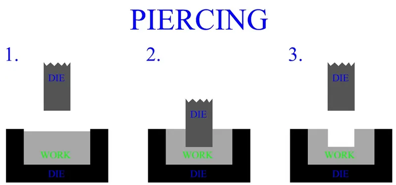
The process results in scratch-free parts regardless of the sheet thickness or complexity of the tool, including undercuts. High forming pressure ensures close tolerance parts direct from the press with little or no secondary hand work required.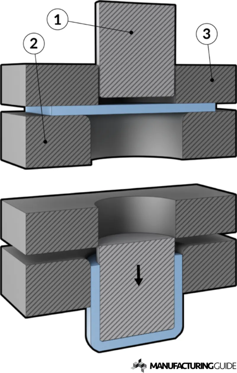 2.Piercing- Piercing is a shearing process in which raw metal is pierced with a machining tool, resulting in the creation of a circular or other shaped hole. As the raw metal is pierced, the metal from the newly created hole is considered scrap. The piercing machine forces a tool, known as a blanking punch, through the sheet metal.
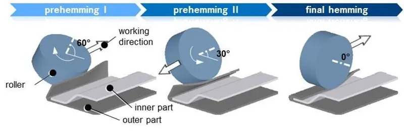
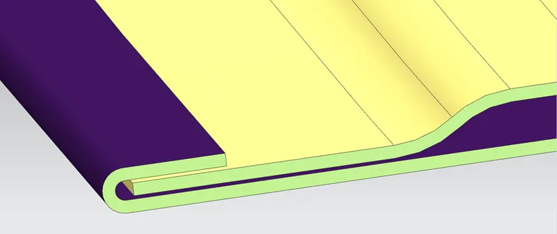
3.Hemming- Hemming is a sheet metal forming process in which sheets are joined by bending it usually to 180°. Automotive body panels and automotive parts such as deck-lids, trunk-lids, doors, hoods and tailgates are formed by hemming process. This paper present a systematic review of sheet metal hemming process based on materials used in hemming process, analytical models, experimental and computational investigations made in the domain of sheet metal hemming process.
CORNER RELIEF-
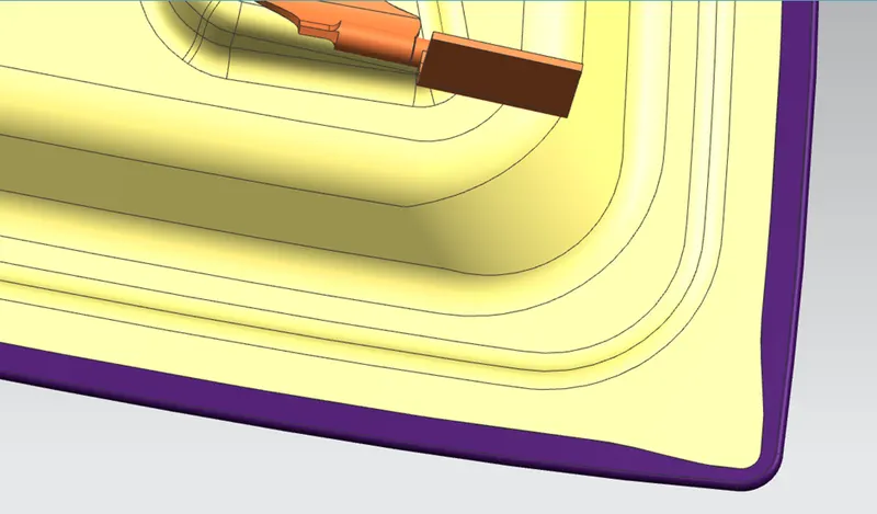
Use the Corner Relief tool to add relief to one or more corners of a sheet metal part. When we add relief, sheet metal sections are removed from the model. we can apply corner relief automatically to all corners or manually to individual sets of corners. Relief helps to control sheet metal material behavior and to prevent unwanted deformation during unbend operations. Here I have provided two relief.
Front relief-
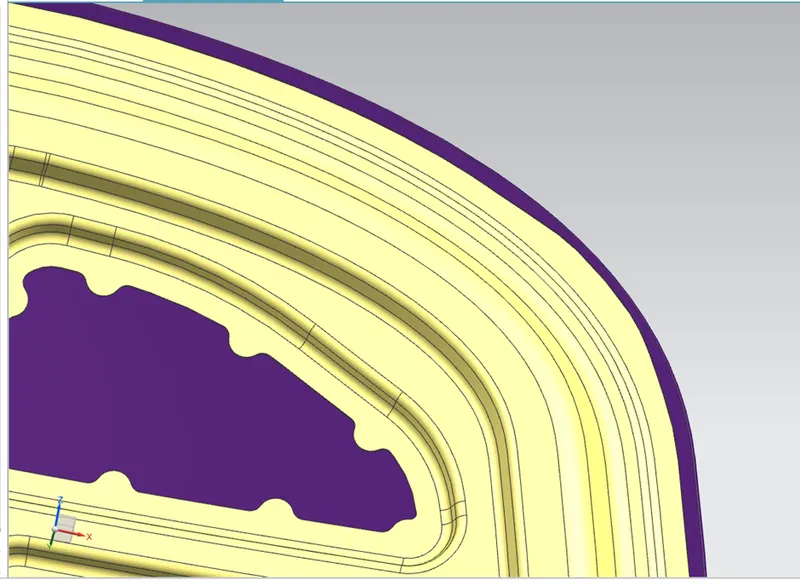
Rear relief-
PROCEDURE-
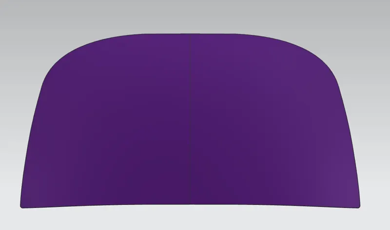
HOOD OUTER PANEL- Outer panels are the aesthetic elements of a car. It is the styling team who provides the skin for the outer panel. The shape, position and size of the hood should satisfy the safety norms. So while designing the hood we should give more importance to pedestrian safety. The outer panel is attached to the inner panel by hemming. So, it is necessary to provide required hemming flange and reliefs for the hemming operation. We also provide mastic sealants between outer panel and inner panel to reduce vibration.
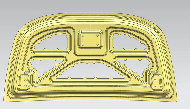
HOOD INNER PANEL- Hood Inner panel is main functional part in hood design. It gives structural support and strength to the outer panel of Hood. The outer and inner panels of the Hood are typically attached together using a hemming operation at the edges.
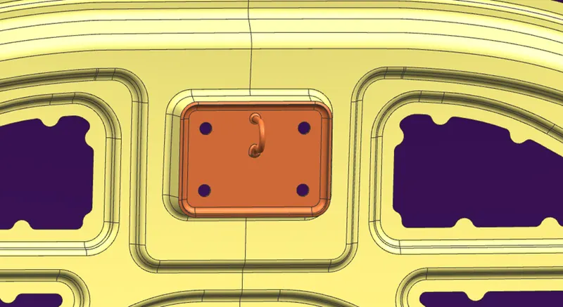
LATCH AND STRIKER- This system is the attachment of hood assembly and vehicle body. The hood latch system must be able to catch the striker of the hood upon closing and instantaneously, as well as automatically, lock. Once in the locked state, it must remain locked and only unlock upon the operator’s control.
HOOD HINGE ASSEMBLY- The hinges are used to guide and hold the hood when open & close. Hinge assembly consists of two parts one is connected to the hood inner panel and second is connected to the vehicle body.
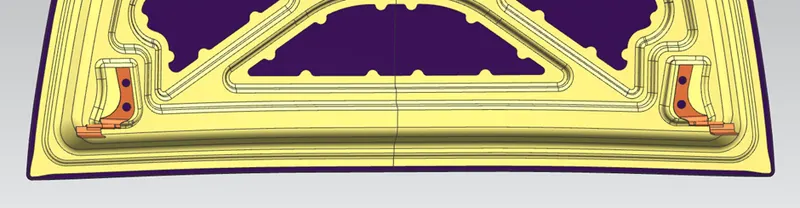
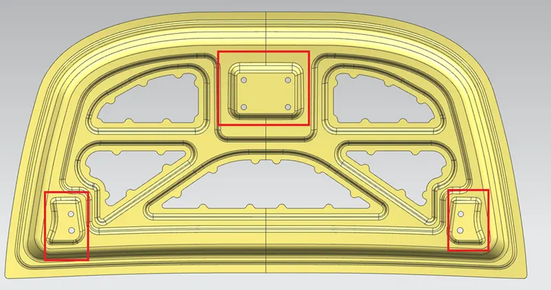
REINFORCEMENT- Reinforcements are provided according to the design requirements. Mainly it is provided at the hinge and latch regions to improve the strength locally. Usually thickness of reinforcements will be higher than that of the inner panels and the value varies according to cost and requirement. According to the design requirement here it is given 1.5mm thickness to both hinge and latch reinforcements.
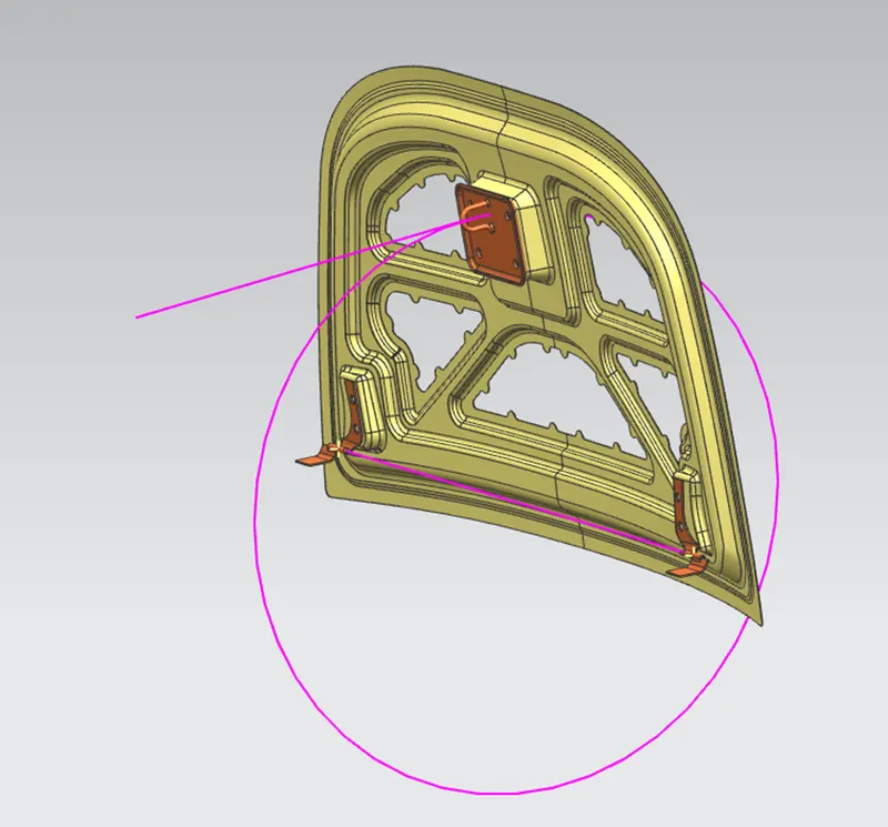
LATCH TRAJECTORY- Latch trajectory is given by the circle drawn from the hinge axis point. Hinge axis point is the centre point of the hinge axis. First, we can fix either the latch or the hinge. If we have fixed the hinge position then we should plot the Trajectory circle for the latch. For proper mating condition the striker axis through the tip of the striker should be tangential to the latch trajectory.
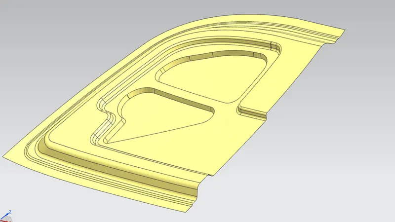
EMBOSS- We provide different embosses throughout the inner panel . We can increase the stiffness of the inner panel through these embosses. The shape and size of the embosses also determines the direction of the force distribution resulted from frontal collision. The force should be always distributed away from the passengers. Here in the figure the embosses are designed in such a way that the force is directed to either sides of the car.
MASTIC SEALANT DATA- Mastic sealants used between the outer and inner panel. mastic sealants are the rubber like elasic compound which connects the outer and inner panels of car hood at specified points. Mastic sealants are used in the region between the inner and outer panel because other joining process like welding or riveting are not good for car asthetic design. It also helps in improving NVH (Noise, vibration, and harshness) characteristics.
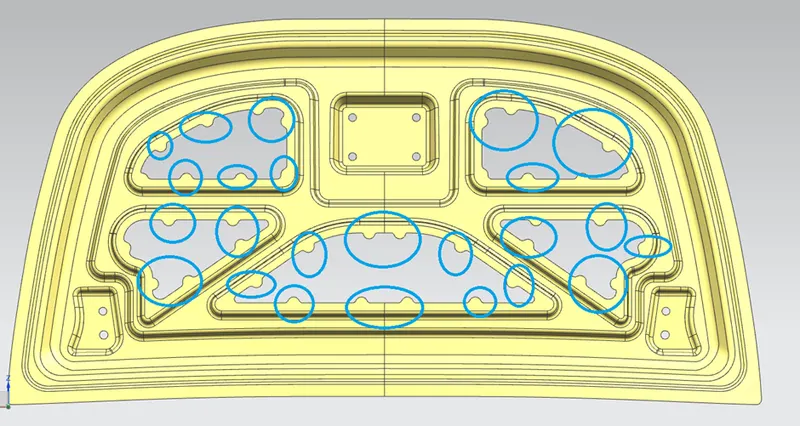
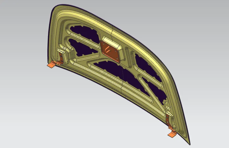
FINAL ASSEMBLY-
ISOMETRIC VIEW-
FRONT VIEW-
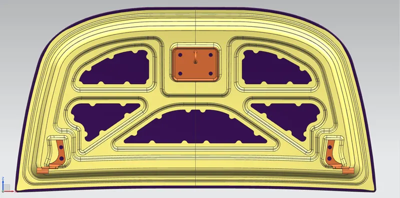
TOP VIEW-
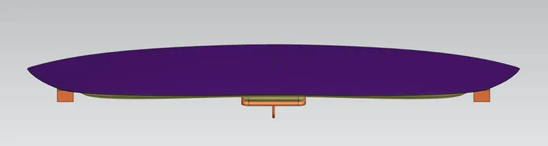
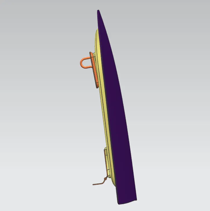
SIDE VIEW-
CONCLUSION-
In this project I learned to design the hood inner panel, outer panel with the help of master sketch and the styling surface. And also learnt the assembly of Hood inner panel, Outer panel, and the reinforcements like latch and hinge assembly.