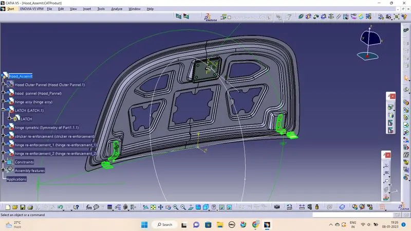
Hood design-Week 2
Aim:
to create a hood assembly with the given input using Catia V5.
Hood inner panel:
- the given surface is offset to 0mm distance first so that the input can be saved in separate geometrical set and also easily to compare.
- As per the given input data the input surface is offset to 1.7mm, 4mm and 25mm.
- Then the edges are applied fillet in the edges.
- now the first emboss is offset to 10mm from reverse direction.
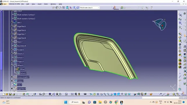
- the next emboss is set to 10mm offset from the previous emboss.
- and the cut-out has been made with sketches.
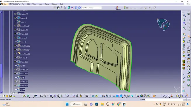
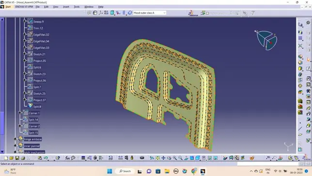
- now the surface is symmetric respect to the yz plane.
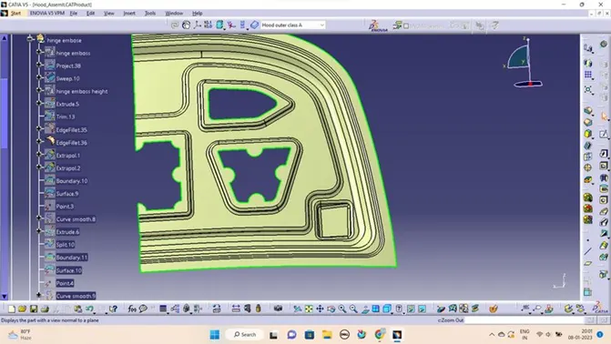
- now for the hinge emboss sketch has made in the surface and projected with the projection curve option.
- now using sweep option the surface is created respected to the 10 deg of drafting angle.
- now axis system is created in the edge of the hood panel surface. and drawn a line parrel to the horizontal axis and extrude it. now trim all the surface respectively.
- and the minimum edge fillet of 5mm is given then mounting hole for hinge is create.
- Now the inner panel surface is ready for Stricker assy.
Stricker Assy:
- to create a Stricker emboss the full hood assembly is taken and opened the Stricker part in the assembly workbench.
- now the Stricker is set in the perfect place with the manipulation option.
- now create a circle that is hood trajectory. In these path only hood ahd stricker should travel. Draw atangent line in the circle.
- now go to the stricker assembly part and extract the boundary of the u natch guide. now draw a centerline along with vertical axis in the possitioned sketch. now use co-ordinate constrain in with the vertical line to the line tangent to the circle .
- then again constrain it with the point so that the stricker or latch is set in the defined trajectroy. if we change the circle dia then the position of latch moves accordingly. now set the position latch possition accordingly.
- the bottom surface is extract from the main part and the boundary is extracted. these are taken as input for the sweep commend.
- now trim the surface.
- the emboss area are made by deep drawing and punching process for cut-out section.
- the extract all the surface for the mounting hole and project it on the main surface and trim it.
- now for the corner relief took the corner option and split it respectively.
- now go to the part workbench and thicken the surface to solid for 0.75mm
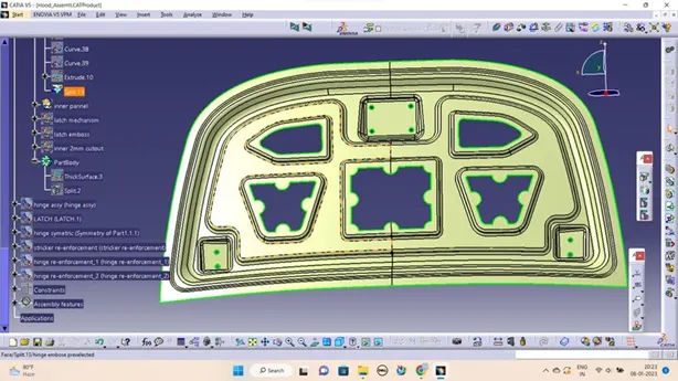
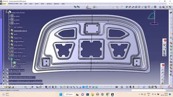
Stricker Positioning:
Reinforcement creation:
- to create a re-enforcement the bottom surface is extracted to 1.5 mm and thicken it to 1.5mm.
- generally latch and Stricker area provided with the reinforcement.
- these is set to additional strength for the attachment.
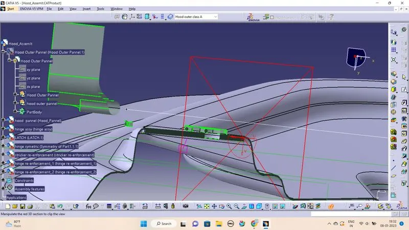
Hood Outer Panel:
- The given input surface is set to offset for 0mm distance.
- these surface is offset to the thickness of outer panel thickness + hemming thickness+inner pannel thickness +0.2mm for each area contact which is =(0.75+0.75+0.75)+(0.2*2) = 2.65mm
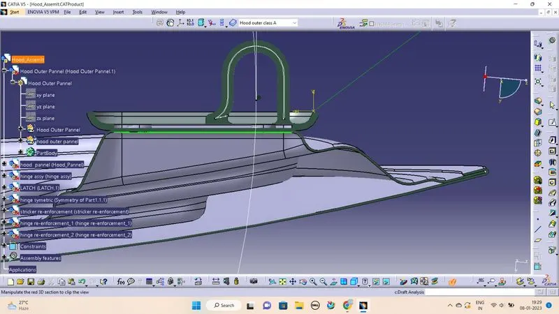
- now took the outer boundary and use parallel curve option for 6mm offset the sweep it to the y direction and split accordingly.
- the both surface is connected with the sweep operation with 2.65mm of height to 90-degree angle normal to the surface. then use the tri-tangent fillet to create the hemming.
- Now clear the 3mm corner relief for front and back edges with the spline and position sketch.
- now thicken the surface.
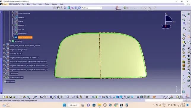
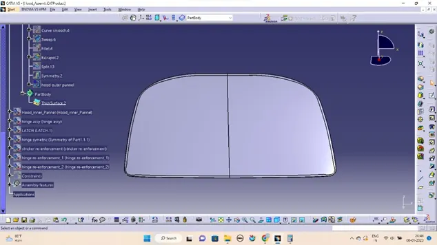
Final Output: