Hood design-Week 2
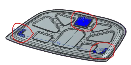
1. Offset surface has been created with 0mm distance (highlighted blue sheet body) for the sake of no changes should reflect on the parent input sheet and the offset has trimmed to pursue the product development of thehood inner panel.
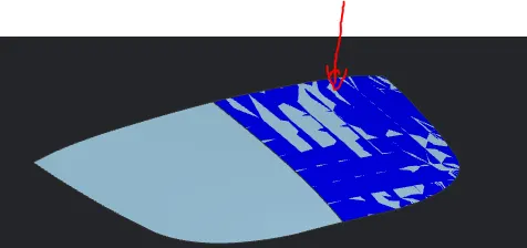
2. As per the reference of the help video of Hood design, have created the inner panel with respect to the master section input data. But I have done alternate approach to create the inner panel as shown in the picture below.
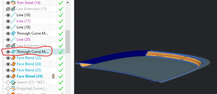
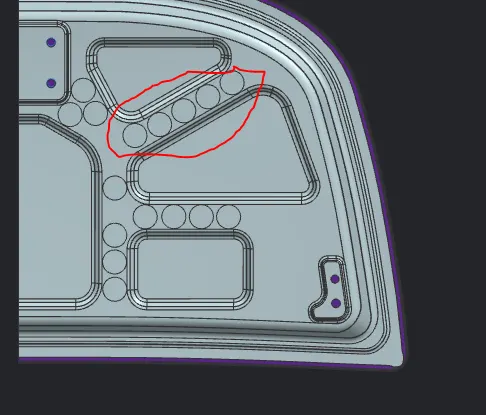
3. Inner surface are embossed in order to dissipate the impact outside when an accident occurs. features are used to form emboss such as sketch, projected curve, offset surface, law extension, trim and blend.
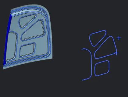
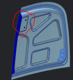
4. Imported the striker input data in order create a bed to assemble the striker position as shown in the picture above.
5. Imported the hinge assembly as an input to locate the position of the base to assemble the hinge as shown in the picture.
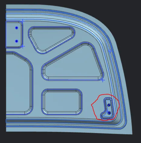
6. Then the hinge base has been created, Thickness has maintained to 0.75mm for both inner and outer panel and the hemming applied to the outer panel in order to hold the inner pane.
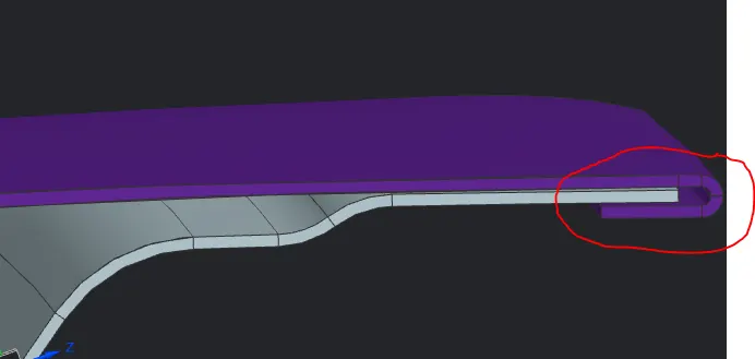
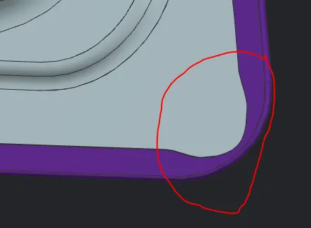
7. corner relief has been applied to the to the outer panel to releave the stress during hemming process.
8. Eventually the reinforcements are placed to observe the vibration to the panel while the engine is on and also on drive.
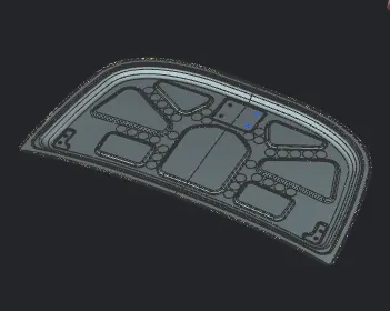
9. By Mirror geometry feature the remaining part has been developed as shown in the picutre above. And the splitted inner and outer panels were united with their respective panels.
10. In assembly module, all input components are assembled with inner panels with the help of assembly contraints.