Fender Design
Introduction
The main task is to be done the surface development of the mountings for the Sill, Bumper,
Baffle(Splash), and A-Pillar. With repsect to the Master sheet the Drip area Monting has been developed from the A - surface. Comprehensively it was a wonderful experinance to work on Fender.
Breif summary of FR-Fender design.
1. Drip Area mount
1. As per the guidance of Fender design course video and the refernce help video found the areas where the mounting areas for Drip, sill, baffle and bumber and their limits
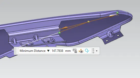
to be designed by maintained 150 mm from SC-SC to the edge of the bumber mounting corner and maintained 200mm over from SA-SA edge and to the A-pillar mounting edge by the help of features curve on surface and trim sheet.
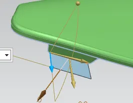
2. First I have chosed the drip area to develop and upon the master section, fetched the parameters to develop the mounting of the drip area
for the point A - G by using the feature Law extension to create a sheet by an angle vector perpendicular to the surface.
3. To create the points J, L, & N areas by calculating Tan Theta and its adjucents and purpendicular angle found those face lenghth by refering
the help video.
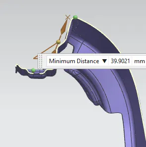
4. Total length of the drip area is maintained 40mm or less and verified the length 200 mm or over where the tool accesability for
fastening to fix the drip to mount to the engine compartment.
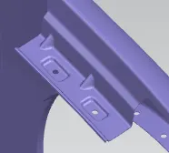
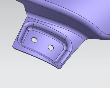
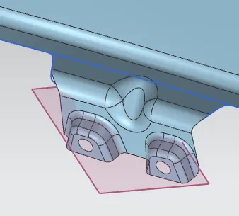
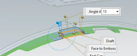
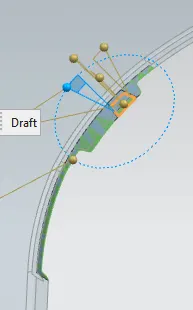
5. Once after all the parametrs are attained and have cretaed an rectangular emboss where the area mates to the engine compartment
and made two holes with 5 mm diameter to faten the screws.
6. finally to avoid the vibration on the drip surface as it is a lenghty suraface made two darts to stranthen the drip surface and after that applied blends to all corners of the two mating surafces.
2. A - Pillar
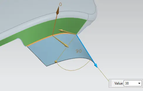
1. After the drip area design adjucent end where the A-pillar mount has been developed and its cut outs also been removed in order
to mount a surface approx.38 mm that can be created by feature law and extension purpandicular to the surface.
2. Blends,rectangular emoboss and 5 mm holes have been created in order to mount the A-pillar area.
3. Side Sill
1. The side sill mount has been developed at the bottom of the fender panel to be attached to the body of the car.
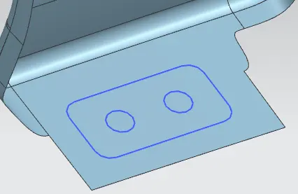
2. As usual in order to mount the sill area to the car body a rectangular emboss with two holes to fatsen the screws.
3. Applied proper blends to the edges to make sure the manufacturing feasibility.
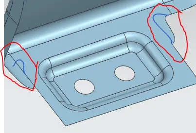
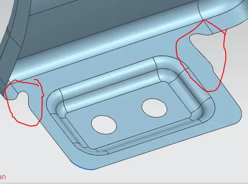
4. During manufacturing there will be a chance of more impact on the corners of the sill mount, releifs are created to reduce the damage or impact on the mount.
4. Bumper mount
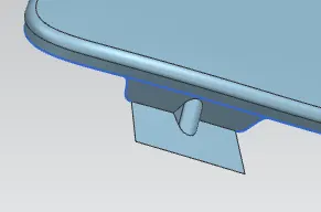
1. The Bumber flange / mount created by removed adjucent faces by curve on surface and trim sheet options.
and then 30 mm purpendicular sheet in order to fix the fender into bumper mount.
2. to avoid the vibration on the mount I have created a dart in the mid of the sheet and it is finished by blends.
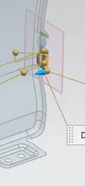
3. Two rectanglar embosses created in order to mate the fender edge with bumber as shown in the screen shots.
5. Baffle mount
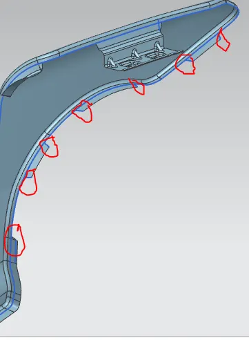
1. The Bumber flange / mount created by removed adjucent faces by curve on surface and trim sheet options.
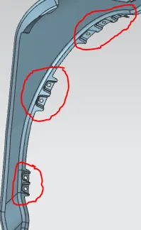
2. The embosses has been created to the respective three baffle mounts and the depth of the emboss can be controlled by offset the baffle mount region into 5 mm.
3. Blends are applied to all sharp edges to make the part as per the manufacturing feasibility.
Conclusion.
Eventually with the support of master section and knowledge learned from the fender design session the fender design part has been executed and it was really a wonderful experiance to learn this part indeed.