Hood design-Week 2
REPORT on Hood Design
AIM- To Design Hood outer panel, inner panel and the necessary reinforcements by following the Master section mentioned with the design parameter, (Hinge,Striker) included.
Design Methodology
1. Develop the inner panel with
- Embossing (with minimum 7 Degrees Draft)
- Mastic Points
2. Develop the Outer Panel with
- Hemming
3. Positioning the reinforcements
- Hinges
- Striker for Latch
Given data for Hood Creation
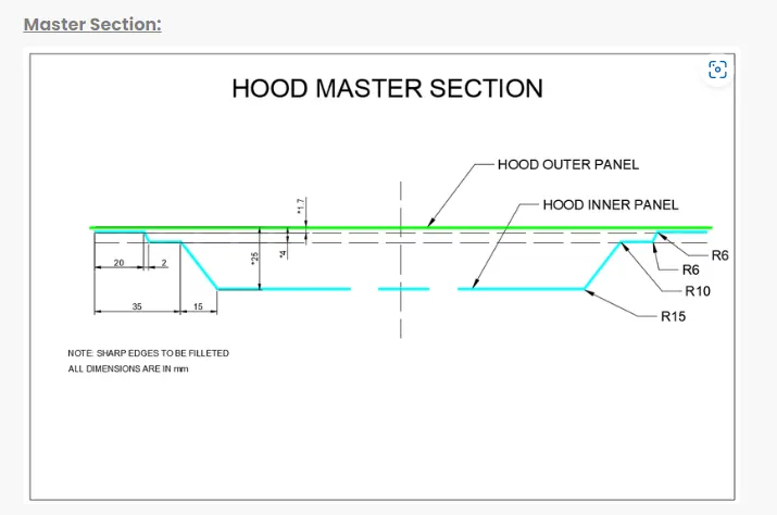
MasterSection
It has played very important role as it has every general design information considered for a hood. It shows general dimensions and structural shape of general hood design.
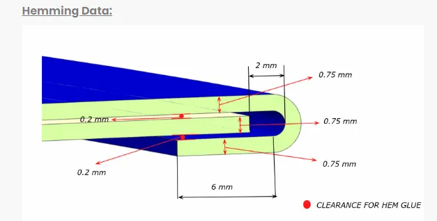
Hemming Data:
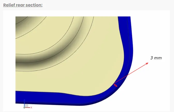
Relief rear section:
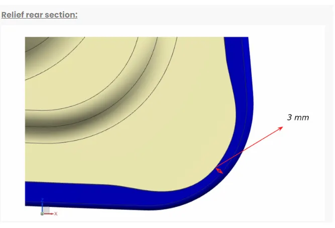
Front relief:
Data To be used
Outer Panel Thickness 0.75mm
Inner Panel Thickness 0.75mm
Reinforcement Thickness 1.5mm
Hood Introduction
The hood (North American English) or bonnet (Commonwealth English) is the hinges cover over the engine of the motor vehicles. Hoods can open to allow access to the engine compartment, or trunk (boot in Commonwealth English) on rear-engine and some mid-engine vehicles) for maintenance and repair.
Hood Design Facilitates
- Hood Covers all engine components
- Easy access in engine compartment
- Frontal Crash impact forces absorption
- Reduce Engine Noise
- Aerodynamic Shape
- Safety of Pedestrain
- Good Aesthetic appearence
Hood Types
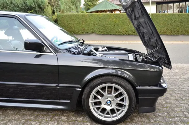
Front Hood

A flipfront hood
Rear Hood

Styles and materials
On front-engined cars, the hood may be hinged at either the front or the rear edge, or in earlier models (e.g. the Ford Model T) it may be split into two sections, one each side, each hinged along the centre line. A further variant combines the bonnet and wheelarches into one section and allows the entire front bodywork to tilt forwards around a pivot near the front of the vehicle.
The Ford Model T Hood Opening
Hoods are typically made out of the same material as the rest of the body work. This may include Steel, aluminium, Fiberglass or Carbon fiber. However, some aftermarket companies produce replacements for steel hoods in fiberglass or carbon fiber to make the vehicle lighter.
Features
A hood may contain a hood ornament, hood scoop, power bulge, and/or wiper jets.
Hood Scoop
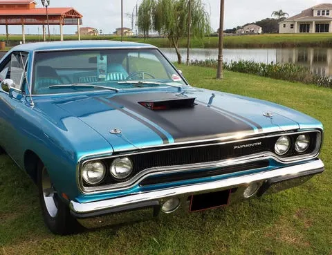
Power Bulge On a Hood
Some hoods may need a power bulge to fit over the engine and air filters, or enhance the aesthetic appearance of the hood.
For Hood Design Considered points
- Opening Angle of Hood
- NCAP Crash Test Ratings For Strength
- Wrap Around Distance (WAD) for Pedestrian Safety
- NVH (Noise, Vibration, Harshness) For Consumer/Customer/User/Buyer
Opening Angle of Hood
This is one of the main criteria in designing of hood. This opening angle varies from person to person and country to country. In India, the average height of a person is 5.8 feet/ 177 cm (Current data) whereas in the European countries the average height is 6 feet, these points refers variation in opening angle of hood.
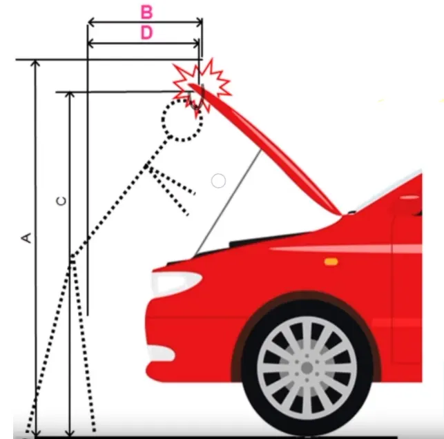
Opening angle is considered as an important criteria, when the opening angle is less than required there are possibilities of human head injury.
Types of Hood Support
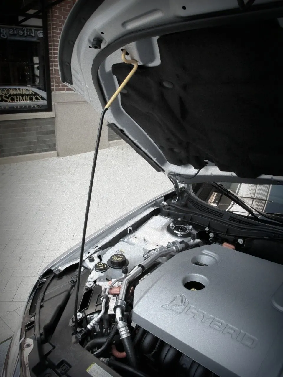
- Support Rod- These support rods are widely used in cars to support the hood in open Position. These support rods are cost effective compare to gas stay. In this type of hood support the hood opens manually. The support rod is fixed on the hood or the engine compartment, to hold hood (in Open Position) the support rod needs to positioned(manually) on the supporting rod point which is opposite to the support rod position. Generally these support rods are used only in the lighter weight hood Vehicles.
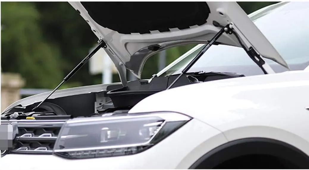
- Gas Stay - These Gas stay are type of support rods which is used for heavy weight hoods. In these gas stay rods, pressurized gas is filled which helps to hold the hood in open position. Gas stay just needs the initial force to open the hood. Gas stays are convient to use but these are expensive when compared to support rods.
Gas stay Holding Hood Open
NCAP Crash Test
Euro NCAP, or the European New Car Assessment Programme to give it its full name, is an independent crash-test safety body, which rigorously assesses the safety of cars, and helps to further the advancement of car safety technology. With safety at the forefront of all car makers minds, and many firms and organisations signing up to the ‘Vision Zero’ initiative – which aims to eliminate all deaths and serious injuries from our roads – Euro NCAP’s test programme is an ever-evolving one, with its architects periodically updating crash-test regimes to ensure cars are assessed using the most stringent criteria possible. The current Euro NCAP safety regime includes a dual rating, with cars tested both with and without various high-tech safety features. This means some cars may get five stars if they are configured with autonomous emergency braking, for example, but drop to four stars for the second rating if this feature is not standard.
The European New Car Assessment Programme (Euro NCAP) is a European voluntary car safety performance assessment programme (i.e. a New Car Assessment Program) based in Leuven (Belgium) formed in 1996, with the first results released in February 1997. It was originally started by the Transport Research Laboratory for the UK Department for Transport, but later backed by several European governments, as well as by the European Union. Their slogan is "For Safer Cars".
Pedestrian safety
In Japan and Europe, regulations have come into effect that place a limit on the severity of pedestrian head injury when struck by a motor vehicle. This is leading to more advanced hood designs, as evidenced by multicone hood inner panel designs as found on the Mazda RX-8 and other vehicles. Other changes are being made to use the hood as an active structure and push its surface several centimeters away from the hard motor components during a pedestrian crash.
Protecting the Head
The hood of most vehicles is usually fabricated from sheet metal, which is a compliant energy absorbing structure which poses a comparatively small threat. Most serious head injuries occur when there is insufficient clearance between the hood and the stiff underlying engine components. A gap of approximately 10 cm is usually enough to allow the pedestrian’s head to have a controlled deceleration and a significantly reduced risk of death. Creating room under the hood is not always easy because usually there are other design constraints, such as aerodynamics and styling. In some regions of the hood it can be impossible. These include along the edges on which the hood is mounted and the cowl, where the hood meets the windshield. Engineers have attempted to overcome this problem by using deformable mounts, and by developing more ambitious solutions such as airbags that are activated during the crash and cover the stiff regions of the hood. Some models, like the Citroën C6 and Jaguar XK feature a novel pop-up bonnet design, which adds 6.5 cm (2.5", C6) extra clearance over the engine block if the bumper senses a hit. In 2012 and 2015, the Volvo V40 and the Land Rover Discovery Sport have an under-the hood airbag designed to operate if the hood senses a hit. The airbag is also designed to cover the windshield pillars to help protect the pedestrian's head.
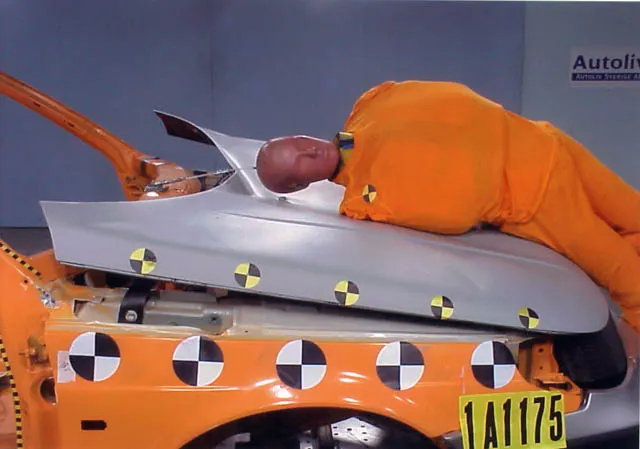
Head Impact
Safety is th most important criteria in automobile design which concentrates on both pedestrian and occupant safety. The pedestrians are the most vulnerable road users are at high risk of traffic accidents. The major reason for fatality of the pedestrian in traffic accidents is due to the head injury resulting fron the hard impact of the head against the stiffer hood of the ground. This leads to the necessity of new inner hood panel which is less stiffer an pedestrian friendly.
The head impact analysis on the present hood assembly was done to observe the local and global stiffness. In order to reduce the head injury of the pedestrian the local stiffness over the area of head impact has to be reduced thus the new design of hood inner panel was focused on that and the structural and model analysis was done for the new design. The design with local stiffness and similar global stiffness compared to the existging hood was finalized.
Car-pedestrian acciddents account for a considerable numbers of automobile accidents in industrialised countries. Head injury continues to be more concerned with automobiles impacts, because the head is the most seriously injured part in many collisions including in pedestrian automobile collosions. To reduce the severity of such injuries international safety committee have proposed sub-system tests in which head foam impactors are impacted upon the car hood.
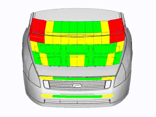
Wrap Around Distance (WAD)
When a car crashes on the pedestrian, the whole human body wraps around the front shape of the car, and the head impacts on the bonnet or the windscreen. The distance at which the head impacts on the car from the ground is mentioned as wrap around distance (WAD).
To be specific the Wrap Around Distance is a measurement of the distance from the ground to the head impact zone over the outer surface of the car. The wrap around distance is measured longitudinally in the centre of the vehicle from the ground.
The severity of the injury caused by the frontal crash depends on the type and shape of the vehicle, the speed of the vehicle, and the movement of the pedestrian relative to the vehicle. In addition to these parameters, the wrap around distance plays a major role in the safety measures of a pedestrian.
During crash analysis, based on the wrap around distance, two test areas will be created namely the Child Head Impact Zone and the Adult Head Impact Zone.
Test Area
- The child and adult head impactor test will be considered for the regulation.
- Test area for child head impactor: 1,000mm ≤ WAD ≤ 1,700mm
- Test area for adult head impactor: 1,700mm ≤ WAD ≤ 2,100mm
Impactor
- Child head impactor: Diameter 165mm, weight 3.5kg
- Adult head impactor: Diameter 165mm, weight 4.5kg
Noise, Vibration, Harshness (NVH)
Noise, Vibration and Harshness (NVH) is the study and modification of the noise and vibration characteristics of vehicle, particularly cars and trucks. To improve NVH, mastic sealants were provided on the inner panel to attach with outer panel. Here mastic points on the inner panel plays a major role to avoid Noise and Vibration into the cabin. NVH is measured by the instruments, namely microphones, accelerometers and force gauges, or load cells. Component and subassembly NVH tests are most commonly performed using a vibration shanker while entire vehicles usually on the test track or road stimulator testbeds.
NVH Test system (With Microphones,etc.)
NVH Road Test Track (Live Conditions)
MANUFACTURING PROCESS
POINTS CONSIDERED FOR FEASIBLE MANUFACTURING
- Minimum Draft of 7 Degrees given for sheet metal - For easy removal of component from tool(Die)
- Sharp edges are avoided for easy manufacturing
- Complex shape is avoided.
Sheetmetal operations
- Deep Drawing
- Embossing
- Hemming
DEEP DRAWING:
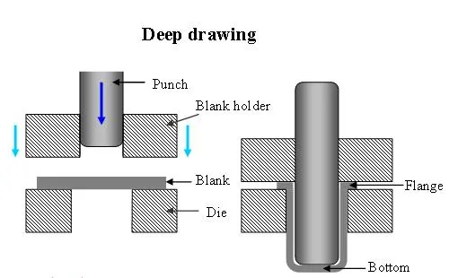
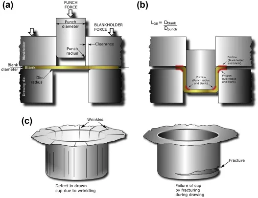
- Deep drawing is a sheet metal forming process in which a sheet metal blank is radially drawn into a forming die by the mechanical action of a punch. It is thus a shape transformation process with material retention. The process is considered "deep" drawing when the depth of the drawn part exceeds its diameter. This is achieved by redrawing the part through a series of dies. The flange region (sheet metal in the die shoulder area) experiences a radial drawing stress and a tangential compressive stress due to the material retention property. These compressive stresses (hoop stresses) result in flange wrinkles (wrinkles of the first order). Wrinkles can be prevented by using a blank holder, the function of which is to facilitate controlled material flow into the die radius.
EMBOSSING
Embossing is a stamping process for producing raised or sunken designs or relief in sheet metal. This process can be made by means of matched male and female roller dies, or by passing sheet or a strip of metal between rolls of the desired pattern, theoretically with no change in metal thickness, or by passing sheet or a strip of metal between rolls of the desired pattern.
- Metal sheet is drawn through the male and female roller dies producing a pattern or design on the metal sheet. Depending on the roller dies used, different patterns can be produced on the metal sheet.
- Emboss should be in 7 degree to 25 degree inclinte in angle and it should not be in 90 degree angle,why because when we do stamping in manufacturing the stamping tool fits the sheet metal hence it will not come out of that sheet metal,So this is the main reason why the emboss face is in angle.
Characteristics of the metal embossing process include:
- Its ability to form ductile metals,
- Its use in medium to high production runs,
- The ability to maintain the same metal thickness before and after embossing,
- The ability to produce unlimited patterns, depending on the roll dies, and
- The ability to reproduce product with no variation.
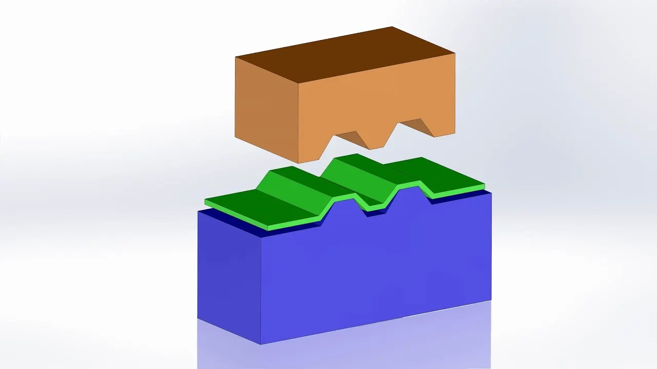
Simple Image of Embossing
HEMMING
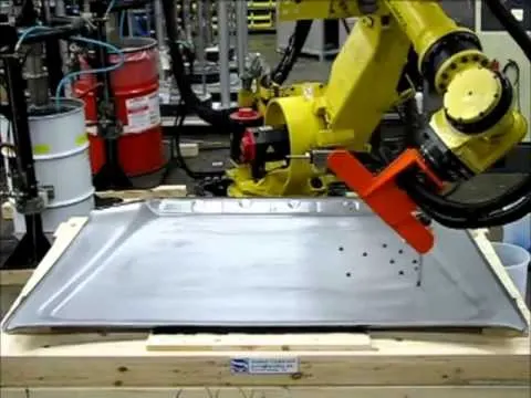
Hemming is a forming operation in which the edges of the sheet are folded or folded over another part in order to achieve a tight fit. Hemming is a technology used in the automotive industry to join inner and outer closure panels together (hoods, doors, tailgates, etc.). It is the process of bending/folding the flange of the outer panel over the inner one. The accuracy of the operation significantly affects the appearance of the car’s outer surfaces and is therefore a critical factor in the final quality of a finished vehicle.
- In hood design, hemming is used in assembly as a secondary operation after deep drawing, trimming and flanging operations to join two sheet metal parts (outer and inner) together.
Roll hemming - In roller hemming process, a robot guides a small roller across the flange to fold a sheet onto itself or onto another sheet. The process is oriented to low volume automotive applications, providing a distinct advantage in manufacturing closures and subassemblies with developed flanges.
MASTIC SEALANT
A mastic sealant is a type of liquid sealant that cures in an elastic state, thus making it flexible while holding the bond of the surfaces that has attached together. It adheres to just about any material making an all-purpose type of sealant.
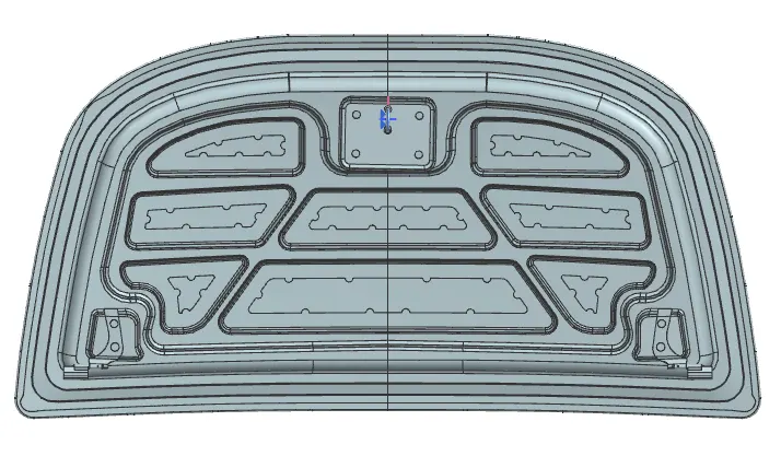
- The main purpose of the outer panel is for the aesthetic looks. Thus we cannot use bolts or welding. This has to be done with the help of the hemming and mastic sealants. Mastic sealants are elastic compound that behaves like the rubber. It is placed between the outer and inner panel. Initially is it in paste form, but after the hot furnace bath it gets hardened thus joining the outer and inner panel. Mastic sealant has the tendency to increase the strength of the panel and has influence of 80mm diameter.
PROS
- One positive characteristic of mastic sealant is that it has a very smooth exterior while keeping its rigid form underneath.
- Surfaces do not have to be primed when using this type of sealant, and although applied thick, it adheres smoothly to any surface. It is important that the area to be joined or sealed be clean and dry, just like any other sealant on the market
- Mastic sealant may be used outdoors as well because of its waterproof quality. It can be applied on rain duct leaks outdoors, for example.
- It is also favored for areas under high or low temperatures such as heater vents or drier vents and contains ultraviolet inhibitors to make sure that it is protected from damaging effects of the sun that will often weaken other types of sealants. That makes it a good choice for use on roofs, or any surface that is constantly exposed to sunlight. Most mastic sealants will also work well with metal because they do not corrode over time.
- It functions well in areas with mild vibration and heat, like hood, heating ducts.
CONS
- Mastic sealant is not recommended for areas that have too much joint movement, or anything that will be moved a long length.
- It works well with constant pressure on it, but not constant movement.
- It also works best when applied thickly and is not recommended if only a thin layer is needed such as touch ups. Another sealant is a better choice for those types of repairs
MASTIC SEALANT POINTS
80 mm diameter
REMOVAL OF MATERIAL
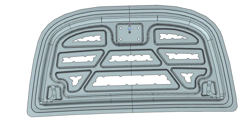
For less impact on head in collisions(Pedestrain Safety), reduce tool cost, reduce material cost, ease of manufacturing and to make light weight.
POSITION OF STRIKER AND HINGE
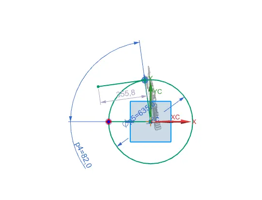
For the proper opening and closing of the hood, the striker should be perpendicular to the trajectory of the hood. For this, hinge is assembled at its position. Once it is placed, hinge axis is drawn.
- To check the hinge axis as the center we draw a big circle to the position the latch in such a way that it is perpendicular to the hood trajectory.
- In between the two hinges, the striker is perpendicular to the midpoint of two hinges, because while closing and opening of latch and striker the opening position be similar actions.
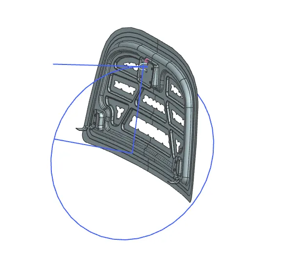
LATCH TRAJECTORY
The latch trajectory shows the path of the striker when the hood is opened and closed on a vehicle.
The radius of the circular trajectory is determined by the set standard based on the average height of a person. The radius is measured from the hinge axis up-to the latch.
STRIKER ANGLE OF HOOD
HINGE ASSEMBLY
Hinges is the assembly of components connected to the door and body of the vehicle, linked to each other and capable of rotating around the same axis. Conventional system consists of two hinges for each door, an upper hinge and a lower hinge.
STRIKER ASSEMBLY
The door striker plates are installed in the door jambs, and precisely aligned with the door latches so that the latches catch onto the striker plate when the doors are closed. The door striker plate is made of hardened steel to resist wear as it is subjected to constant contact with the door latch.
The hood latch system begins inside the compartment of the car, hood release handle located onthe driver's side. The hood release handle attaches to a cable which then routes through the dashboard towards the front of the vehicle.
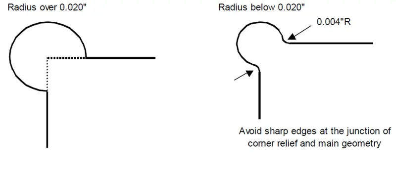
CORNER RELIEF
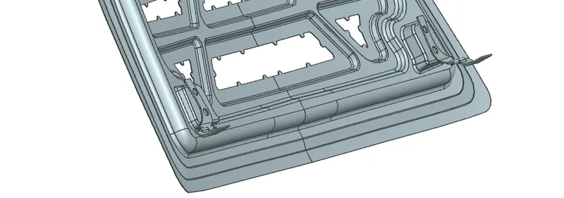
- Relief is provided onto the part or component in order to remove any stresses developed in a particular area i.e sharp corners that takes place during the hemming process is carried out. Thus corners are rounded or chamfered.
- Relief of 3 mm from sheet metal for Roll hemming process.
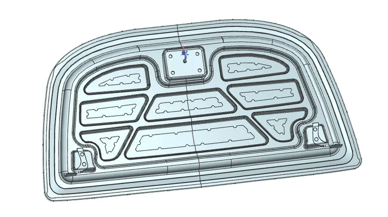
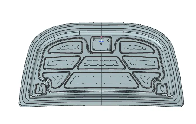
DIFFERENT VIEWS OF HOOD
FRONT VIEW
TOP VIEW
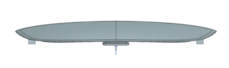
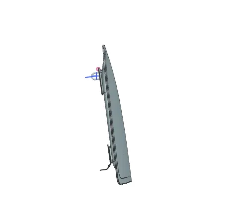
SIDE VIEW
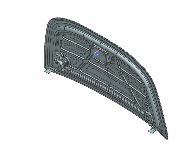
ISOMETRIC VIEW
CONCLUSION
This hood was designed in Siemens NX Student Version software with given and required design guidelines for hood design and manufacturing.