Photo Realistic Rendering
DESIGN OF AMERICAN CHOPPER
INTRODUCTION:-
This Project based on the Design of American Chopper and This Report Contains Brief explanation of designing of American Chopper By using Solid works software , from initial to final sketch including solid modelling ,surface modelling tool explanation with dimension.
OBJECTIVE:-
The main objective of this designing is to obtain sustainable knowledge in solid part modelling.
1) Detail designing of each component parts with proper relation of all part model.
2) Get clear vision of solid works interface and make custom shortcuts of tools, tool bar, command manager commands.
3) Accurate Assembly of Designed parts with proper relations of all part model.
4) Become Professional in using Decal, Lights, Appearance (metal, rubber glass etc.), Environment, Back plates.
5) Obtain knowledge in Solid works Visualize and Photo view 360 Rendering tools to make realistic renders of the modelled chopper.
PART MODELING:-
It is the process of which modelling of a component object in 3D by using the 2D sketch by using tools and sketch constraints ,features of solid works like boss revolve ,extrude , trim , chamfer, fillet etc.
METHODOLOGY:-
1) PART MODELING
2) ASSEMBLY
3) RENDERING
COMPONENTS TO DESIGN
- Transmission belt
- Kick stand
- Front fender
- Rear fender
- Chain
- Oil tank
- Pedal
- Front wheel
- Rear wheel
- Front fork
- Chassis
- Engine
- Gas tank
FEATURES AND TOOLS:-
Used for modelling will be explained in separate topics each component design.
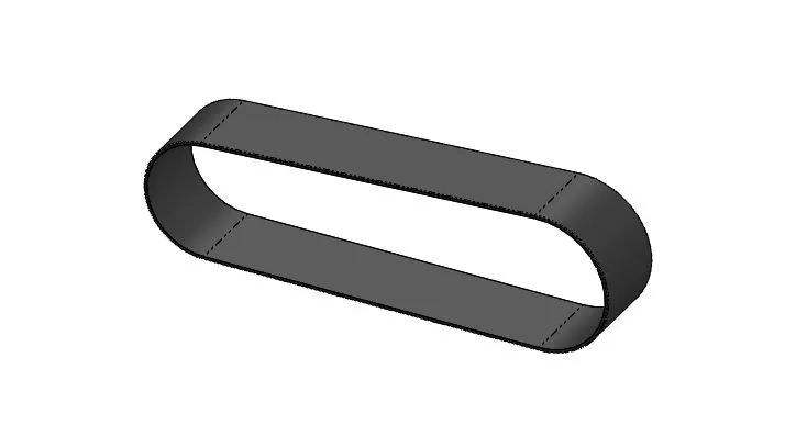
TRANSMISSION BELT
Component Description: Transmission Belt is used to transmit power from one end to another of pulley
Features:-
- Boss Extrude: - Used to expand the object in 3D according to sketch plane.
- Fillet:-Fillet is a feature used for making round edges to avoid sharp edges
Constraints used:-
- Tangent
- Midpoint
Tools used
- Line tool:-Used to draw straight and tangent arcs
Methodology:-
Using Line and arc constraints making a sketch with given dimension offset the sketch with entities after get defined sketch make extrude using boss extrude of belt model make 1mm fillet at edges of transmission belt
IMAGE
KICK STAND:-
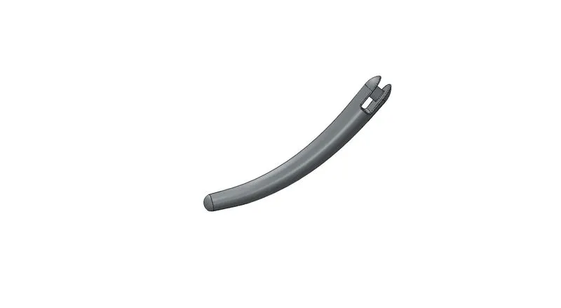
COMPONENT DESCRIPTION: - It is supporting mechanism which is used to prevent the chopper lean on ground and makes upright without interfere with a person or object.
Features:-
- Extrude boss base - Used to expand the object in 3Daccording to sketch plane
- Fillet - Fillet is a feature used for making round edges to avoid sharp edges
- Lofted Boss base - Lofted boss is a feature used to achieve complex shapes .which basically
Extruded loft surface by means of two lofted profiles along with guided curves direct the path of lofting
- Split – Split tool is used to split single solid part into two solid parts
Constraints used
- Coincident
- Midpoint
Tools Used-
- Ellipse –used to make elliptical sketches as per dimension
- Spline – Spline tool used to make spline curves and complex geometry shapes
- Centre Point – It is used to make rectangle based on centre point rectangle.
METHODOLOGY:-
Create an ellipse according to vertical and horizontal dimensions after that make a spline in perpendicular plane. with reference of spline and its end point creating another plane for draw another loft profile after sketching by using loft boss base feature create aloft profile spline as guide curve to make perfect loft needed after that make a dome in the side of stand which going to lean in ground and finally make a flat surface to lean in ground by using split tool
IMAGE
FROND FENDER
Component description:-
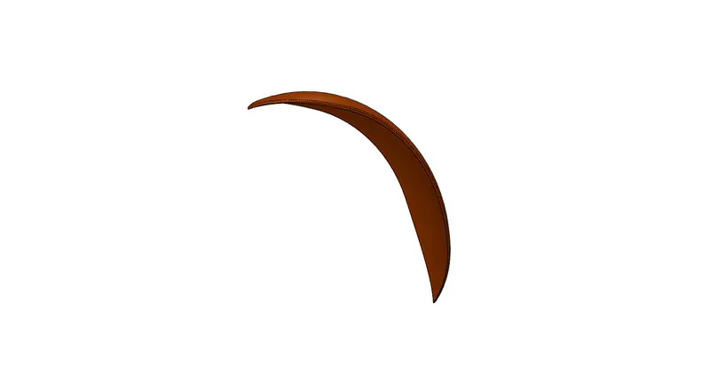
Fender is a frame like structure which is laying over a wheel is used to prevent the mud,
Liquid, slippery things will be flown into air while rotating at the high speed also it prevents the small stones will be flown over a rider because of acceleration cover a tyre
Features Used:-
- Revolve Boss Base: - Revolve features is used to make cylindrical or circular 3D extrude along with a given reference axis as per drawn sketch
- Split – Split tool is used to split single solid part into two solid parts
- Fillet:-Fillet is a used for making round edges to avoid sharp edges.
- Dome: - Dome is feature used to make dome shaped extrude including elliptical dome.
- Extrude Cut: - Extrude cut feature used to cut the 3D object in linear path according to sketch.
Constraints Used:-
- Reference axis for revolve
Tools Used:-
1.3Point Arc: - 3 Point arc used to draw an arc with make centre point as reference point draw an arc.
- Spline: - spline tool is use to make spline curves and complex geometry shapes
- Dynamic Mirror: - Dynamic Mirror used to mirror the entire feature of the plane selected for mirroring.
- Extent Entities: - It is used to extend end point lines to make closed sketch
- Trim Entities: - Trim is used to trim delete the additional lines in the geometry
Methodology:-
Creating 3 point arc as per dimension with offset and using extend entities to make complete the sketch by making a reference axis by means mid plane which by means of axis using revolve feature by two direction at specific angle
After that making a spline to obtain required shape with dynamic mirror option
Image:-
REAR FENDER:-
Component Description:-
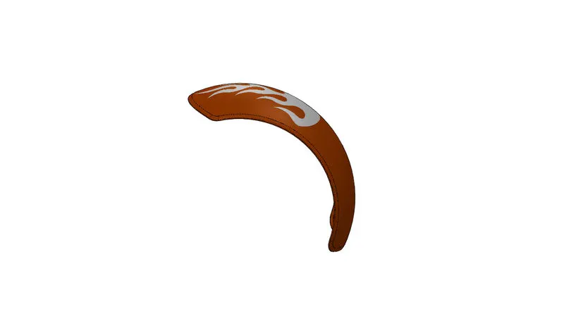
Fender is a frame like structure which laying over a wheel is used to prevent the mud, Liquid, slippery Thing will be flown into air while rotating at high speed also it prevents the small stones will be flown over a rider because of acceleration over tyre. Its same work as front fender.
Features Used
- Revolve Boss Base: - Revolve feature is used to make cylindrical and circular 3D extrude along with a given reference axis as per drawn sketch
- Split – Split tool is used to split single solid part into two solid parts
- Shell –Shell feature is used to make to hollow space in solid part by selecting outer wall of the solid part is to make remove the inner parts also used to reduce the specific thickness
- Fillet: - fillet is a feature used for making round edges to avoid sharp edges.
Constraints Used:-
- Horizontal
- Vertical
Tool used:-
1.3Point arc: - 3Point arc used to draw an arc with make centre point reference point draw an arc
- Spline: - Spline tool is used to make spline curve and complex geometry shapes
- Extent Entities: - it is used to extend the end point lines to make close sketch
- Trim Entities: - Trim is used to trim delete the unwanted lines in the geometry.
Methodology:-
Creating a 3 point Arc at mid plane of rear fender at a offset line at a given distance at end of the arc line draw and extend using extend entities, as reference of construction lines making revolve feature at two direction and angle needed to achieve fender after that make split at end of the fender to get curvature by using 3 point arc at last by selecting face of fender to make full fillet at edges at last to make shell command to reduce the thickness of the fender at given dimension.
Image:-
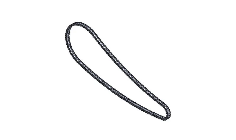
CHAIN:-
Component Description:-
Chain is used to transmit the power from one point to another point like power from engine to sprocket at rear wheel for acceleration of vehicle.
Features Used:-
- Extrude Boss Base:-Used to expand the object in 3D according to sketch plane.
- Fillet: - It is used to make round edges and avoid sharp edges
- Curve: - It is driven pattern is used to make any pattern which followed y the curve is sketched before
Constraints Used:-
- Concentric
- Coincident
- Tangent
Tools Used:-
- Circle- Circle is the tool used to draw a circular sketch
2.3point Arc: - 3 Point Arc used to draw an arc with make centre point as reference point draw an arc.
3.Blocks:- Block are the tool which make a particular sketch as block that we can get a sketch as block able to insert in geometry and sketch any time.
- Trim: - Trim is used to trim delete the additional lines in the geometry.
Methodology:-
Started with two circle which located at constructions line reference after that draw a 3point curve which is tangent with two circles with specific radius then trim additional lines after that create a chain pin block
By using that block to make coincident and concentric relation which the chain block make path with the curve which is drawn. After fixing block with curve make extrude the pin and chain plates at offset then make a curve driven pattern by curve as reference by following the same rhythm to create a complete chain model.
Image:-
OIL TANK:-
Component Description:-
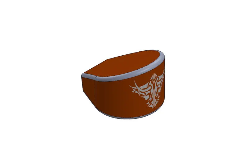
Oil tank is used to store oil or fuel. And its maintain the internal temperature at cylindrical blocks because of ignition for which the oil stored in a tank is known as oil tank.
Features Used:-
- Extrude Boss Base:-Used to expand the object in 3D according to sketch plane
- Fillet: - Fillet is used to remove sharp edges and provide circular edges.
3.Shell:-Shell feature is used to make to hollow space in solid part by selecting outer wall of the solid part is to make remove the inner parts also used to reduce the specific thickness.
- Combine: - Combine is used to make integration of two solid parts which intersect each other as same solid parts.
Constraints Used:-
- Tangent
- Coincident
Tools Used:-
- Arc-Arc used to draw an arc with make centre point as reference point draw an arc.
- Spline- Spline tool use to make spline curves and complex geometry shapes
- Dynamics Mirror: - Dynamics mirror used to mirror the entire feature of the plane selected for mirroring
- Line Tool: - Used to draw straight, construction line and tangent arcs
Methodology:-
In oil tank start with top plane making line and make tangent arc coincident with construction line make a straight line coincident with sketching point to get fully defined sketch and make a dynamic mirror after that make a extrude
Then make a line with mid plane to make an oil tank and extrude after that make combine both shapes to obtain an oil tank
Make a fillet with all ends .finally make a shell command without selecting body to get hollow tank inside.
Image:-
PEDAL:-
Component Description:-
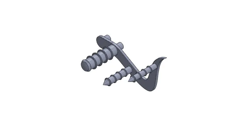
Pedal is used to support for rider to spread his foot on a pedal and make rider comfortable while travelling and prevent foot contact with road.
Features Used:-
- Extrude Boss base: - used to expand the object in 3D according to the sketch plane.
- Fillet: - It is used to make round edges and avoid the sharp edge.
- Revolve Boss base:-Revolve is used to make cylindrical or circular 3D extrude along with a given reference axis as per draw sketch.
- Dome: - dome features is used to make dome shaped extrude including elliptical dome.
- Chamfer: - chamfer is used to make an edges sharp edge to make angled tapering.
- Linear Pattern :- Linear pattern is used make a solid features pattern in path as linear
Constraints Used:-
1 .Tangent
2 .Coincident
Tool Used:-
- Fillet :- Fillet is used for making round edges to avoid sharp edges
- Line Tool: - used to draw the straight, construction line, and tangent arcs.
- 3Point arc: - It is used to draw an arc with make centre point as reference point drawn an arc.
- Offset: - Offset is used make same sketch which is selected at point of given dimension.
Methodology:-
Making a fully defined sketch filled with lots of relation and sketch ended with fully defined sketch as like to get an exact dimension of a pedal.
Then Extrude a fixing pin using a contour selection make pedal frame same as that after that make a revolve of leg rest from the same sketch to get a rest finish making a fillet an chamfer at end of the rest and make a dome an end finally a pattern in a leg support at a pedal is extruded by using linear pattern command.
Image:-
FRONT WHEEL
Component Description:-
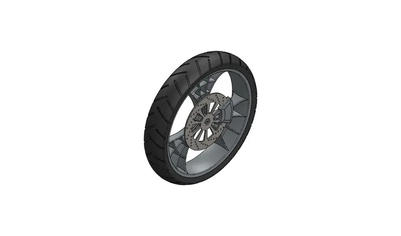
Wheel is used as locomotive component of every vehicle. The wheel generally rotated based on the axis fixed with the vehicle. It’s built with hard rim cover with nylon tyre.
Features Used:-
- Extrude Boss Base: - Used to expand the object in 3D according to sketch plane.
- Fillet: - Fillet is used for making round and avoid sharp edges.
- Revolve Boss Base: - IT is use to making cylindrical or circular 3D extrude along with a given reference axis as per drawn sketch.
- Revolve Cut:-Revolve cut is method to cut or reduce the unwanted circular and cylindrical surface.
- Chamfer: - It is used to make an edges sharp edge to make angled tapering
- Linear Pattern:-Linear pattern is used to make a solid feature pattern in path as linear
- Extrude cut: - Extrude cut feature used to cut the 3D object in linear path according to sketch
- Circular Pattern: - It is used to make 3D feature into circular pattern according to number of insistence
Constraints used:-
- Coincident
- Midpoint
- Horizontal
Tools Used:-
- Fillet: - Fillet is a feature used for making round edges and avoid sharp edges.
- Line Tool: - It is used to draw straight, construction line and tangent arcs.
3.3 Point arc: - It is used to draw arc with make centre point as reference point draw an arc.
- Spline:-It is used to extend line to the next sketch with relation along to the sketch.
Methodology:-
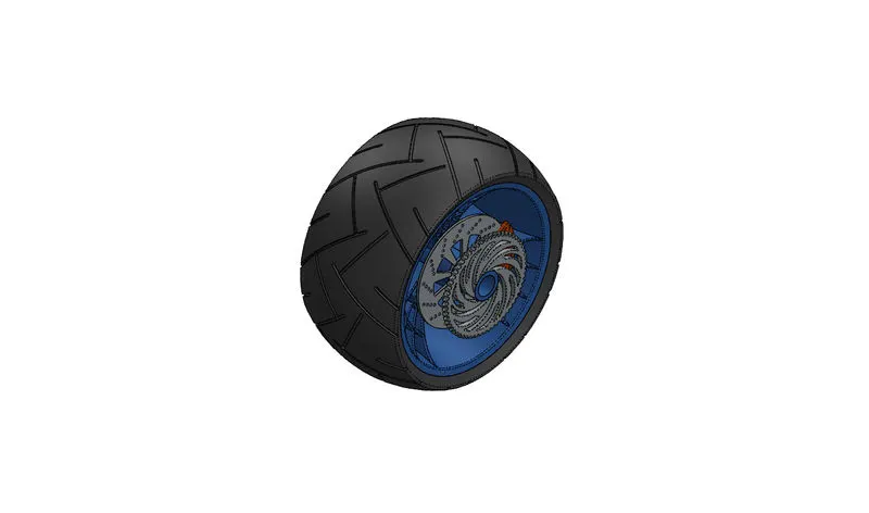
For front wheel it consistent of tyre, rotor calliper, wheel rim.
For Rim:-
The rim is made by extrude revolve in the front plane reference by making sketch and revolve to achieve the rim after making a revolve boss base.
For Rotor:-
Rotor is extrude offset from mid plane to offset at specific dimension and make a circular patterned holes for grip to callipers.
For Calliper:-
It is extrude along with the mid plane extrude at both direction and make fillet and chamfer to achieve calliper
For Tyre:-
IT is done by making revolve with front plane as per dimension to achieve pattern in tyre making a circular pattern feature
Image:-
REAR WHEEL:-
It is used as locomotive component of every vehicle. The wheel generally rotated based on the axis fixed with the vehicle. It’s built with hard rim cover with nylon tyre. It also used sprocket, calliper, rotor, and tyre.
Features Used:-
- Extrude Boss Base: - It is used to expand the object in 3D according to sketch plane.
- Fillet: - It is used to making round and circular edges and remove unwanted edges from part.
- Revolve Boss Base: - It is used to make circular or cylindrical 3D extrude along with a given reference axis as per drawn sketch.
- Revolve Cut:-It is a method to cut reduce the extrude of cylindrical round surface.
- Chamfer:-It is used to make an edges sharp edge to make angled tapering
- Linear Pattern: - Linear Pattern is to make a solid feature Pattern in path as linear
- Extrude cut:-It is used to cut the 3D object in linear path according to sketch.
- Circular Pattern: - It is used to make 3Dfeature into circular pattern according to number of insistence.
Constraints Used:-
- Coincident
- Mid Plane
Tool Used:-
- Fillet: - It is used to make circular or cylindrical edges and avoid sharp edges.
- Line Tool:-Used to draw straight, construction line and tangent arcs.
3.3Point Arc:-It is used to draw an arc with make centre point as reference point draw an arc.
- Spline:-It is used to make spline curves and complex geometry shapes
- Trim: - It is used remove unwanted line.
- Extend Entities: - It is used to extend line to the next sketch with relation along to the sketch.
Methodology:-
For rear wheel it consistent of tyre, rotor calliper, wheel rim, and sprocket.
For Rim: -
It is made extrude revolve in the front plane reference by making sketch and revolve to achieve the rim after making a revolve boss base.
Then making a sketch to do make a spider web like forks by using circular pattern and other sketch entities according to dimensions.
For Rotor:-
Rotor is extrude offset from mid plane to offset at specific dimension and make a circular patterned holes for grip to calliper.
For Calliper:-
It is extrude along with the mid plane extrude at both direction and make fillet and chamfer to achieve calliper.
For Tyre: -
It is done by making revolve with front plane as per dimension to achieve pattern in the tyre making a circular pattern feature.
For Sprocket:-
It is made by extrude from the mid plane of wheel with offset from a distance which is parallel to sprocket at engine block the sprocket is made by circular pattern to achieve the teeth at sprocket
Images:-
FRONT FORK:-
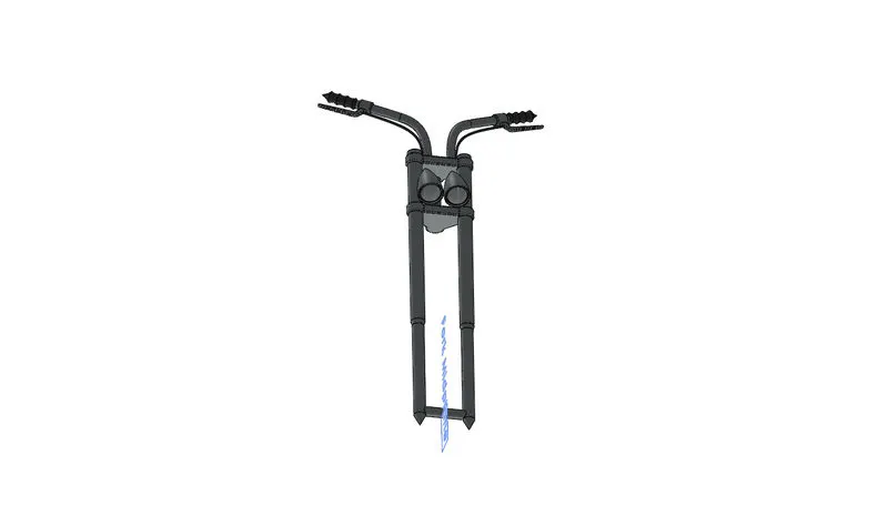
Component Description:-
It is consists two narrow tube consists of two shock absorbers along with axis of front wheel end fixed with handle bar to control direction of vehicle with head light.
Features Used:-
- Revolve Boss Base:-
It is feature is used to make cylindrical or circular 3D extrude along with a given reference axis as per drawn sketch
- Dome:-
Dome is used make dome shaped extrude include elliptical dome
- Extrude Boss Base:-
Used to expand the object in 3D according to sketch plane.
- Split:-
It is used to split single solid part into two solid parts
- Combine:-
It is used to make integration of two solid parts which intersect each other face.
- Move Copy Body:-
It is used to move copy the 3D body to one place to another place
- Mirror:-
It is used to making mirroring body by reference of the selected plane it makes reduces the working timing of the model.
- Sweep: -
It is used to sweep any kind of fully defined sketch along with the path.
Constraints Used:-
- Mid plane
- Coincident
- Horizontal
Tool Used:-
- Projected Curve: - Projected curve is a spherical tool to make work easier projected used to combine a curves from different plane in to single plane sketch my means of integration.
Convert Entities: - It is used to make sketch according to the plane which under sketch a trace of single line.
- Line Tool: - It is used to draw straight, construction line and tangent arcs
- 3 Point Arc: - It is used to draw an arc with make centre point as reference point draw an arc.
- Spline: - It is use to make Spline curves and complex geometry shapes.
Methodology:-
Starting with the long barrel which where suspension located make revolve feature as per sketch sketched at front plane.
From top plane extrude the centre part of fork where head light and speedo meter located offset from some distance, After extrude making right plane make a revolve of head light using move copy features move ahead light towards z direction to make head light centre.
Make a fillet at the end of the head light to get soft round edges.
Make a mirror as plan as right side of solid part which mounted upside of fork make a mirror feature to get complete fork , making revolve of handle bar the a making composite curve to get break wire connected with fork at last make a new for front fork used to assembly.
Image:-
CHASIS:-
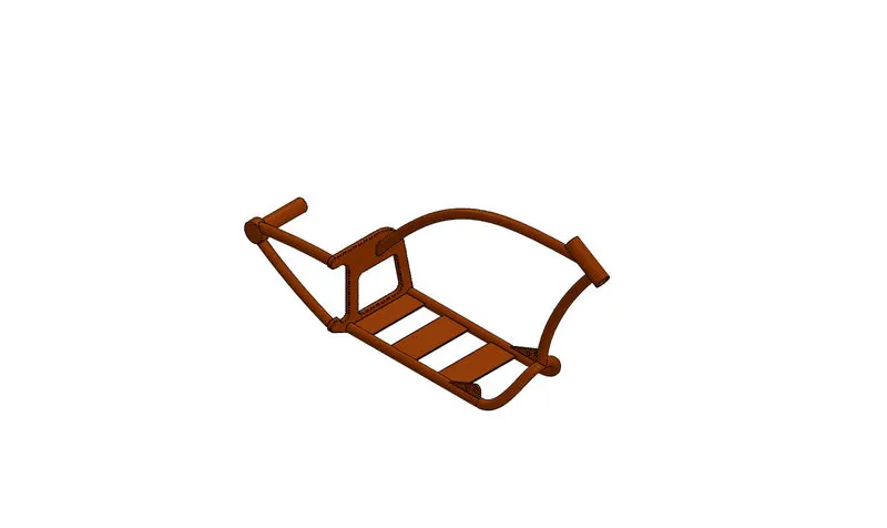
It is Skelton of bike which is main frame that is used to hold everything like Engine, Gas tank, Pedal… each and every parts.
Features Used:-
- Mirror: - Which is used to make Mirroring image by reference of the selecting plane it makes reduce the working timing of the model.
- Sweep:-This Features is used to sweep any kind of fully defined sketch along with the path.
- Revolve Boss Base: - It is used to give circular or cylindrical 3D Shape Extrude along with a given reference axis as per drawn sketch.
- Dome: - Dome is used to make Dome shaped extrude including elliptical dome.
- Extrude Boss Base: - Used to expand the object in 3D according to sketch plane.
- Split: - It is used to make integration of two solid parts which intersect each other as some solid parts
- Chamfer: - It is used to make an edges, sharp edge to make angled tapering.
- Fillet: - Fillet is used to make circular or cylindrical edges and avoid the sharp edges.
Constraints Used:-
- Midpoint
- Concentric
- Coincident
Tools:-
- Projecting Curve: - It is used to make easier projected used to combine a curve from different plane in to single plane sketch my means of integration.
- Convert Entities: - It is used to make sketch according to the plane which under sketch makes a trace of single line.
- Line tool: - It is used draw straight, construction line and tangent arcs.
- Spline:-It is use to make spline curves and complex geometry shapes.
- Circle:-used to make circles according to given radius diameter.
Methodology:-
Need of reference blue print for make chassis by importing chopper blue print using image sketch feature after importing image make sketch with reference of imported image by using splines to make projected curves of bottom part of chassis make sweep along with curve.
Image:-
ENGINE:-
Component Description:-
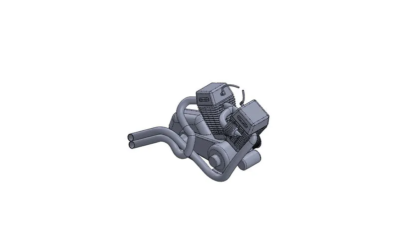
Engine is power House of the vehicle it transmit the power to rear wheel with the help of chain and sprocket wheel.
Features Used:-
- Mirror: - Mirror is used to make a mirroring a feature or body by reference of the selected plane it makes reduce the working timing of the model.
- Sweep: - this feature is used to sweep any kind of fully defined sketch along with the path.
- Revolve Boss Base: - It is used to make circular or cylindrical 3D extrude along with a given reference axis as per drawn sketch.
- Dome:-Dome is used to make dome shaped extrude including elliptical dome.
- Extrude Boss Base: - It is used to expand the object in 3D according to sketch plane
- Split: - Split tool is used to split single solid part into two solid parts.
- Combine: - Combine is used to make integration of two solid parts which intersect with each other as some solid parts.
- Chamfer:-Chamfer is used to make an edges sharp edge to make angle tapering.
- Fillet: - It is used to make circular or round edges and avoid the sharp edges.
- Extrude Cut:-Extrude cut feature used to cut the 3D object in linear path according to sketch.
- Circular Pattern: - It is a feature used to make 3D feature into circular pattern according to number of insistence.
- Linear Pattern: - It is to make a solid feature pattern in path as linear.
Constraints Used:-
- Coincident
- Concentric
- Horizontal
- Vertical
Tool Used:-
- Fillet: - It is used to make circular and cylindrical edges. And avoid the sharp edges.
- Line tool: - It is used to draw the straight and construction Line and tangent arcs.
3.3Point Arc: - It is used to draw an arc with make centre point as reference point draw an arc.
- Offset: - It is used make same sketch which is selected at point OD given dimension.
- Projected curve: - It is a special tool to work easier projected used to combine a curve from different plane in to single plane sketch by means of integration.
- Convert Entities: - It is used make sketch according to the plane which under sketch make a trace of single line.
- Trim:-Trim is used to remove the unwanted line or portion.
- Composite Curve:-It is used to make to Composite two curves into single curve.
Methodology:-
Engine part Modelling need a reference image same as chassis after that using engine Blue Print Make line and tangency for pulley used to drive, after that making an extrude from a new plane from the reference to make an engine block using cut extrude cut the fins in the engine and make mirror after that make an air intake using revolve and projected curve finally making composite curve to sweep the exhaust and make the spark plug cable at the end of the engine block.
Image:-
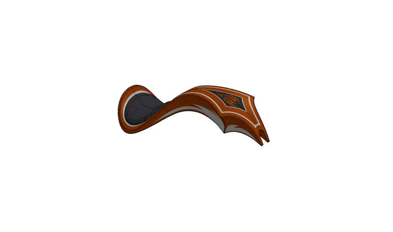
GAS TANK:-
Component Description:-It is used to store the fuel and supply for engine to generated the power in combustion process and move the vehicle.
Features Used:-
- Swept surface: - Its used to make a surface along with the path curve is driven.
- Boundary Surface: - which is used to make the surface in between two finished surface.
- Loft Surface: - Loft surface is use to make a loft in between two profiles along with guide path.
- Knit Surface: - knit surface is used to make knit zipped two surface.
- Sweep Cut: - It is same as Sweep feature but it’s directly proportional to sweep which make a cut along with the sweep path.
- Combine: - It is used to make integration of two solid parts which intersect each other as some solid parts.
7.Shell:-Shell feature is used to make to hollow space in solid part by selecting outer wall of the solid parts is to make remove the inner parts also used to reduce the specific thickness
- Fillet: - it is used for making round edges and avoid sharp edges.
Constraints Used:-
- Tangent
- coincident
Tool Used:-
- Line Tool:-It is used to draw the straight and concentric line and tangent arcs
2.3Point Arc: - It is used to draw an arc with make centre point as reference point draw an arc.
- Projected Curve: - It is special tool to make work easier projected use to combine a curves from different plane in to single plane by means of integration.
- Convert Entities:-It is used to make sketch according to the plane which under sketch makes a trace of single line.
- Mirror:-It is used to make a mirroring a feature or body by reference of the selected plane it makes reduce the working timing of the model.
Methodology:-
In gas tank which is make a surface extrude by making sweep surface extrude making a tangential spline curve along with sweep path to make an outer tank wall.
After that to make projected curve to extrude loft surface using guided curve and make complete gas tank finally make a shell for gas tank because of hollow object to make fully modelled design model.
Image:-
ASSEMBLY OF CHOPPER:-
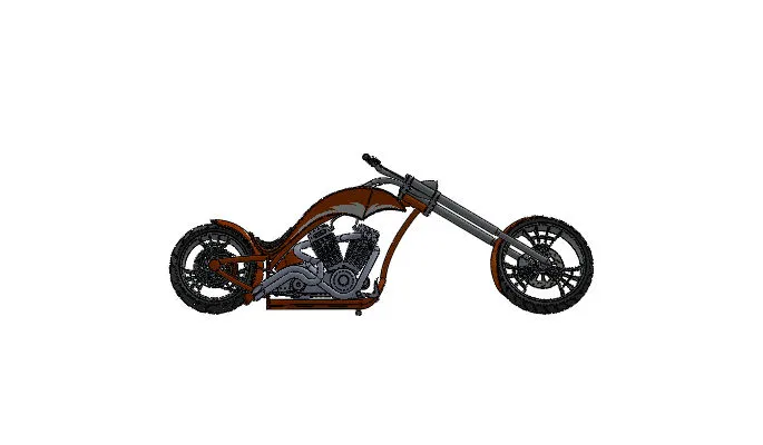
Assembly of chopper which is make an assembly of component which is designed before for an assembly import all components at assembly environment of solid works.
Constraints Used:-
Constraints play a major role for assembly which is used to assemble each parts
- Concentric
- coincident with planes
- Tangent with Planes
- Parallel
- Perpendicular
Etc….
Mates:-
Mates is features used to make mate with each other components properly used to make accurate assembly of a components .there is a type of components.
- Advanced Mate
- Mechanical Mate
Finally apply decals for all the components
Fully Assembly Chopper:-
Image:-
RENDERING:-
It is process of making real time products.
Rendering consists of following features
- Environment settings
- Lights Settings
- Colours and Material Editing
- Scene Composition
Setup of solid works photo view 360 with above mentioned aspects with proper Environment solid works visualize is activated individual rendering setup to make a real time rendering Experience
Conclusion:-
In the American chopper project learn to use a new feature and tools and learn about assembly according to planes of models including advanced mates.
Finally learning about light, environment setup, colour, decals, back plates using photo view 360 and solid works visualize.