Gate Valve Parametric Study
GATE VALVE SIMULATION
Aim- To perform a parametric study on the gate valve simulation by setting the opening
INTRODUCTION
A gate valve is a valve that opens by lifting a barrier (gate) out of the path of the fluid. Gate valves require very little space along the pipe axis and hardly restrict the flow of fluid when the gate is fully opened.Gate valves are used to shut off the flow of liquids rather than for flow regulation. When fully open, the typical gate valve has no obstruction in the flow path, resulting in very low flow resistance. The size of the open flow path generally varies in a nonlinear manner as the gate is moved. This means that the flow rate does not change evenly with stem travel. Depending on the construction, a partially open gate can vibrate from the fluid flow.
PROCEDURE
1. Preparing up Geometry
First the Step file of the gate valve was uploaded on the Spaceclaim. Then "Pull" tool is used to increase the inlet and outlet . Then the bottom of the gate valve was hidden and "move" tool was used to to lift the gate. The gate was lifted by 10mm and then the "P" Symbol was clicked to create it a parameter. Then the fluid volume was extracted by hidden all other components except the bottom and spindle.Then all the components were surpressed for physics
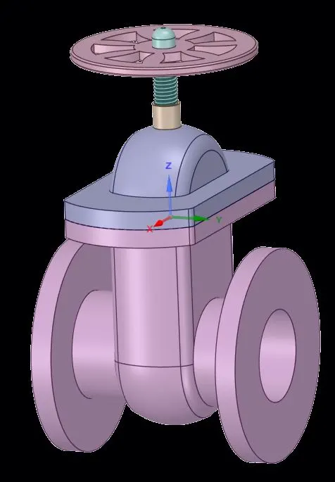
Figure 1.1 Image of Gate valve
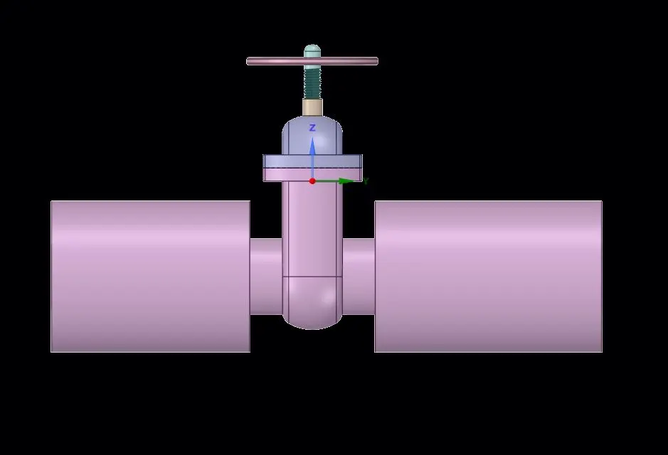
Figure 1.2 Extented inlet and outlet
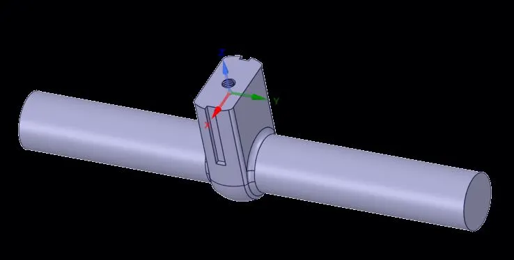
Figure 1.3 Fluid volume
2.Meshing
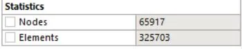
After preparing the geometry meshing owas opened and then a mesh of element size of 5mm was generated. The inlet and the outlet were also named.
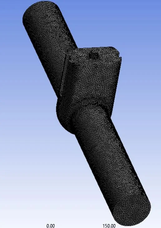
Figure 2.1 Image of mesh

3. Setup
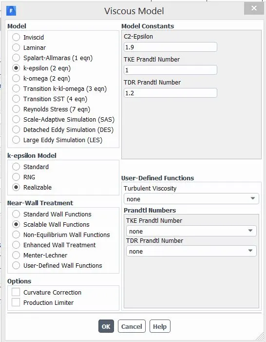
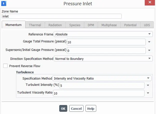
After the meshing fluent was opened.The viscous model was set to Realizable k-epsillon model with scalable wall function.The working fluid is set to water. In boundry condition the inlet was set to "pressure inlet" and the inlet pressure was set to 10Pa. Also a report for mass flow rate and total pressure at the at the outlet was created and were set as outlet parameter. The standard Initialization was done for the simulation.
4. Simulation
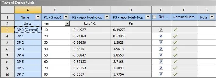
The simulation is done for 8 values of lift of gate disc from 10mm to 80mm
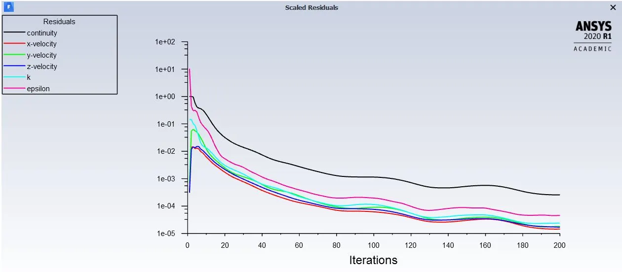
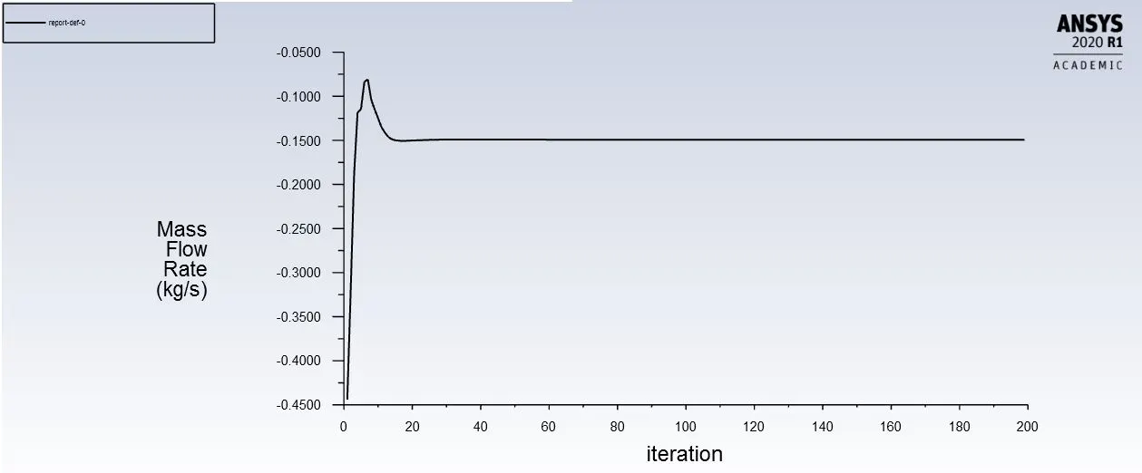
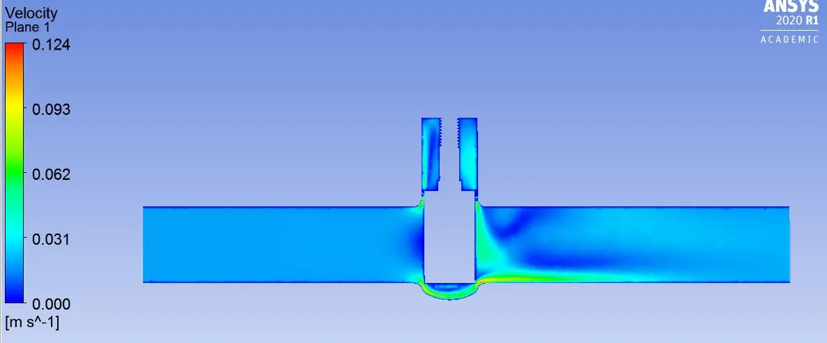
Case 1.1- Lift of 10mm
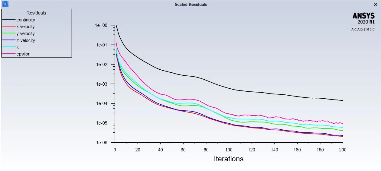
Case 1.2- Lift of 20mm
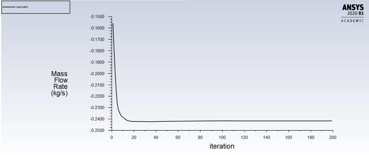
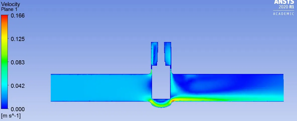
Case 1.3- Lift of 30mm
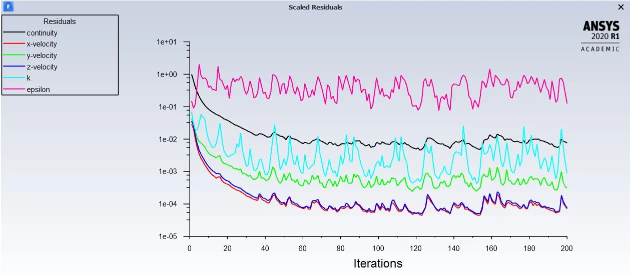
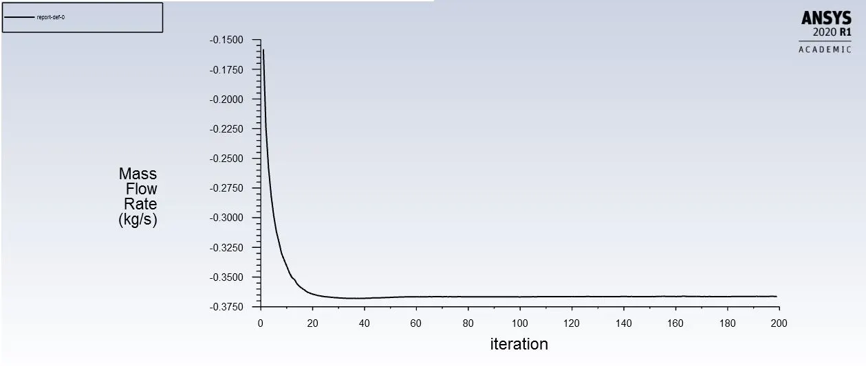
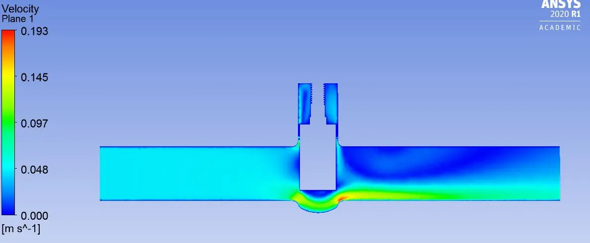
Case 1.4- Lift of 40mm
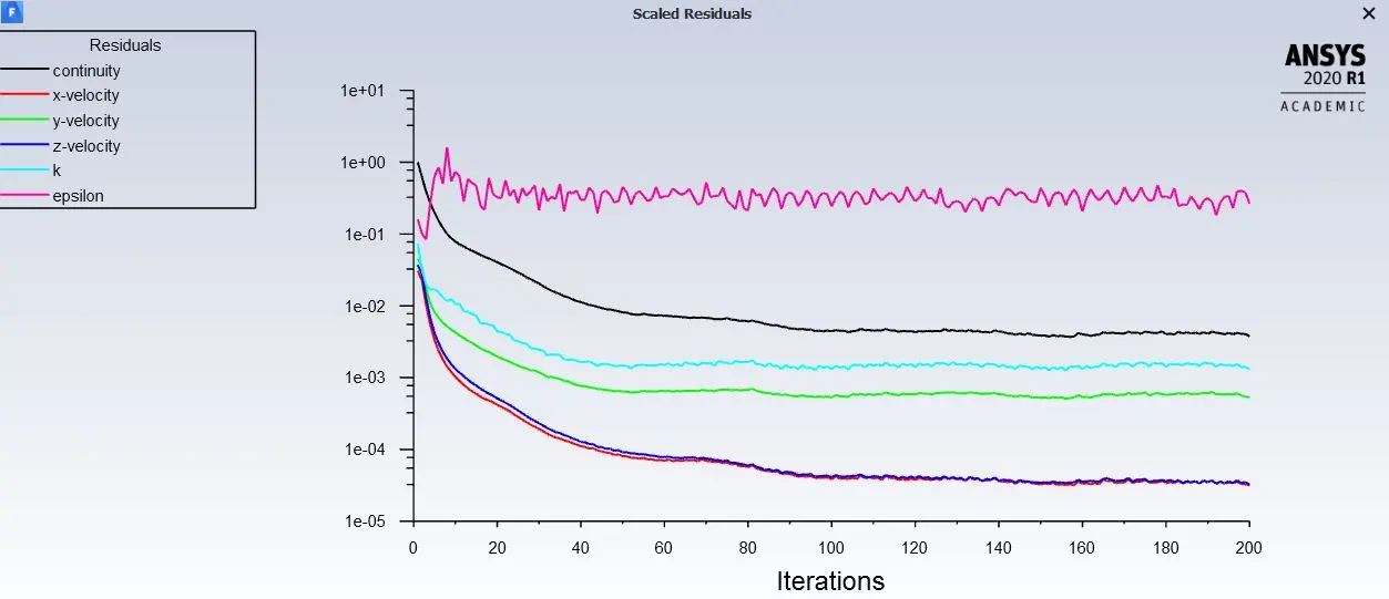
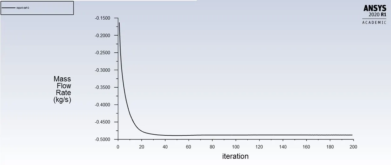
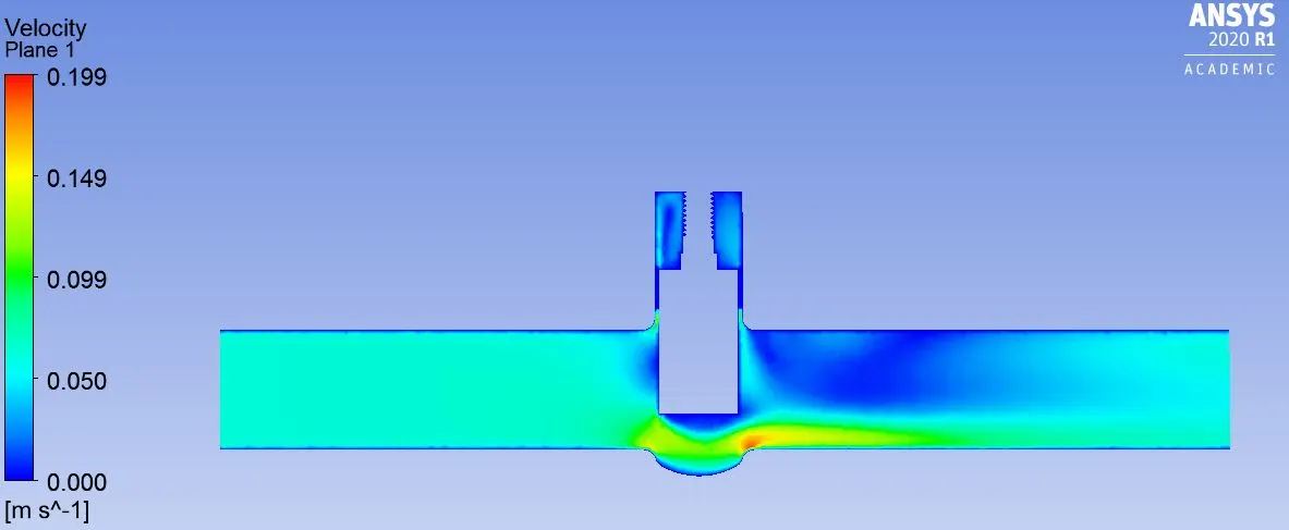
Case 1.5- Lift of 50mm
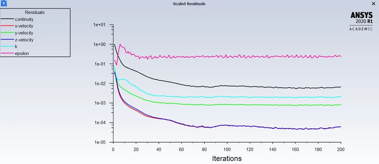
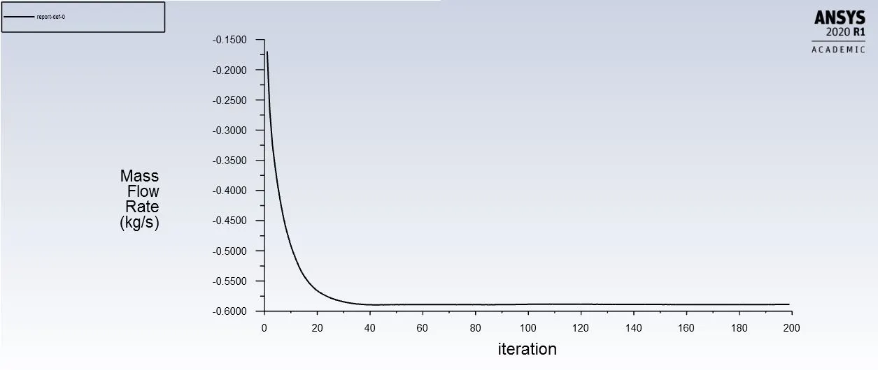
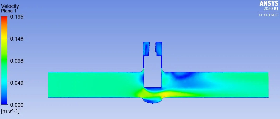
Case 1.6- Lift of 60mm
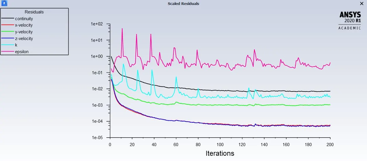
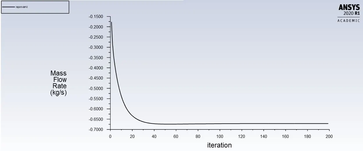
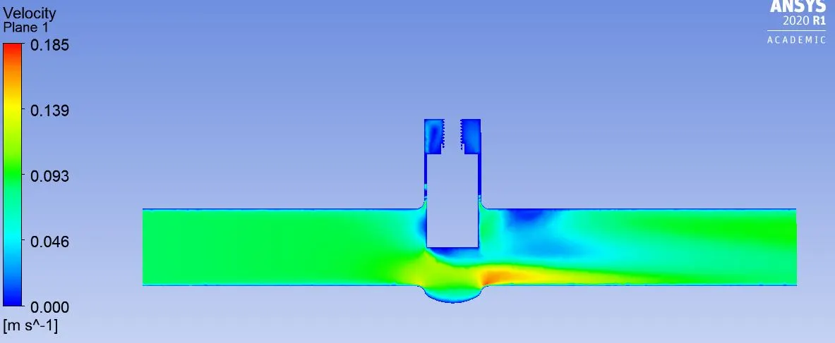
Case 1.7- Lift of 70mm
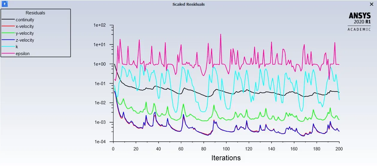
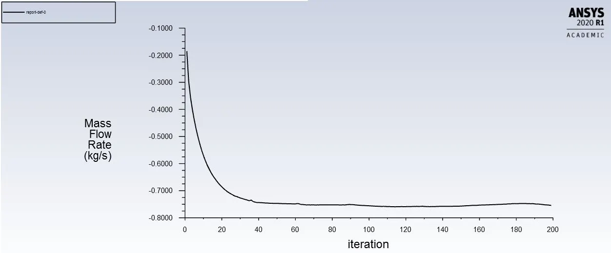
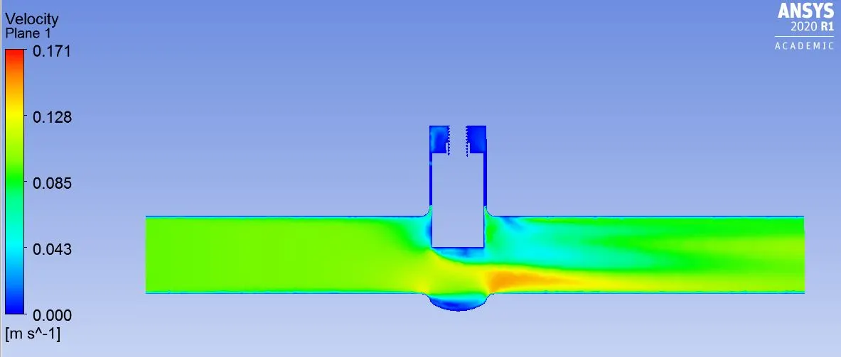
Case 1.8- Lift of 80mm
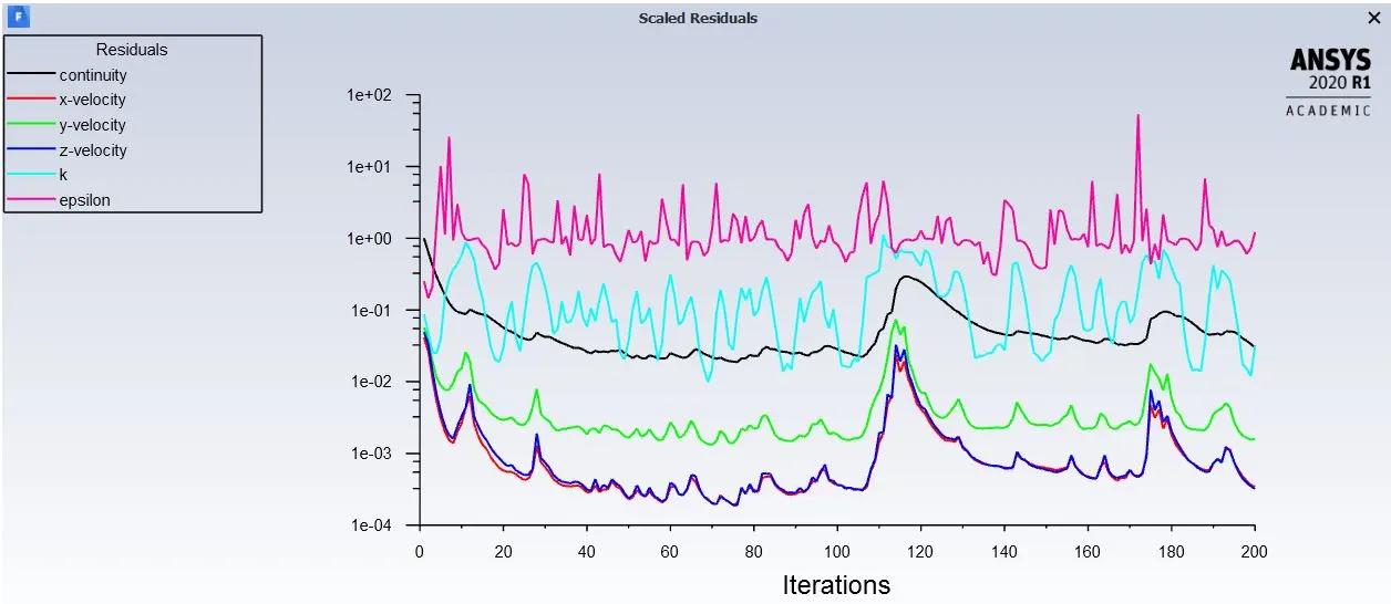
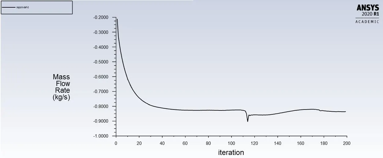
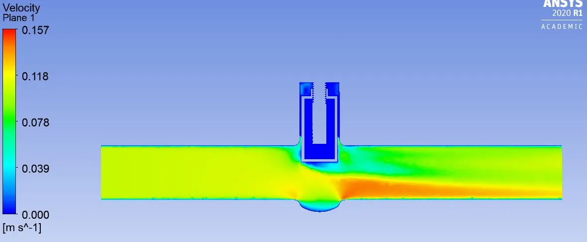
Result
The mass flow rate was calculated for all the lifts of gate disc. The flow coefficient and flow factor was also calculated
for each case.
Flow Coefficient
Flow Coefficient (Cv) is a valve’s capacity for a liquid or gas to flow through it. It is technically defined as “the volume of water at 60°F (in US gallons) that will flow through a valve per minute with a pressure drop of 1 psi across the valve.”
In simpler terms, the larger the opening in a valve, the larger the Cv. As a valve is opening, the Cv increases until the valve is fully open, where it reaches its highest possible Cv, or 100% open Cv.
Cv=`11.6Qsqrt((SG)/P)`
Where:
Q is mass flow rate in `m^3/(hr)`
SG is specific gravity of water
P is pressure drop
Flow factor (Kv)=0.865Cv
| Lift of gate(mm) | Intel Pressure(Pa) | Outlet Pressure(Pa) | Pressure Difference | Mass flow Rate(kg/sec) | Mass Flow rate(m3/hr) | Cv | Kv |
| 10 | 10 | 0.19272 | 9.8072 | 0.14927 | 0.5373 | 1.99 | 1.7213 |
| 20 | 10 | 0.53456 | 9.46544 | 0.24169 | 0.8700 | 3.28 | 2.8372 |
| 30 | 10 | 1.2028 | 8.7972 | 0.36636 | 1.3188 | 5.16 | 4.8526 |
| 40 | 10 | 1.9613 | 8.0369 | 0.4875 | 1.755 | 7.18 | 6.2107 |
| 50 | 10 | 2.8563 | 7.1437 | 0.58847 | 2.1184 | 9.19 | 7.9493 |
| 60 | 10 | 3.7166 | 6.2834 | 0.67133 | 2.4167 | 11.2 | 9.688 |
| 70 | 10 | 4.7049 | 5.2951 | 0.75453 | 2.7162 | 13.7 | 11.8505 |
| 80 | 10 | 5.7754 | 4.2246 | 0.8357 | 3.0082 | 17 | 14.705 |