Gate Valve Parametric Study
Gate Valve Parametric Study
Aim: To perform a parametric study on the gate valve simulation by setting the opening from 10 % to 80%
Parametric study:
A parametric study in Simulation is done to Map the change in inputs to the corresponding outputs. As long as the input parameter and output parameters are connected, the corresponding output values for change in input values are obtained.
In this case, the process begins with the creation of an input parameter group in the Spaceclaim window. The corresponding parameterized output is the mass flow rate.
Geometry:
Gate is 10 mm lifted with the creation of an input parameter group.
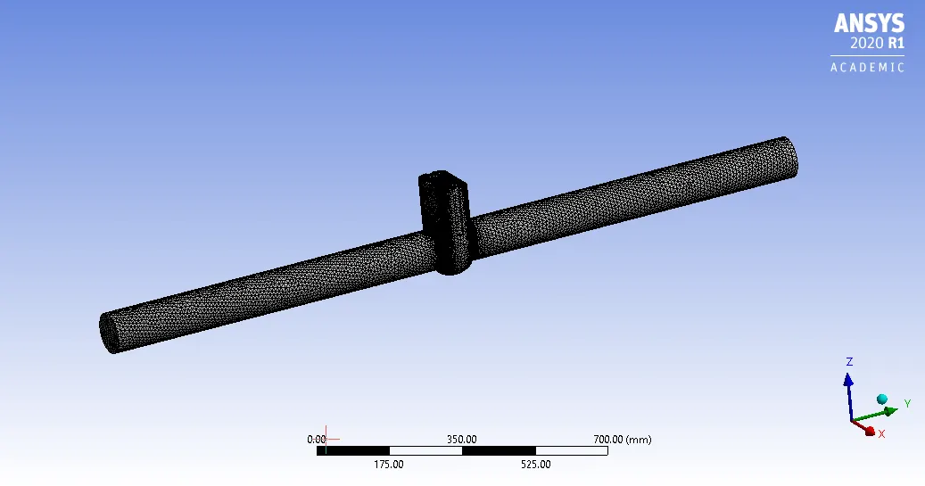
Fluid Volume is extracted and the length of the fluid is increased by 800mm on both sides. Rest all other components are suppressed.
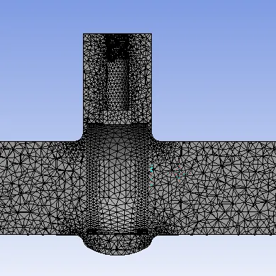
Meshing -
Element Size - 10mm

Setup
- Cell Zone Condition - Water
- Gravity in Z-direction = -9.81 m/s
- Realizable k-epsilon turbulences model with scalable wall function model is used
- Inlet condition-pressure inlet with 10 pa (gauge pressure)
- Surface Report of Volume Flow Rate and pressure, Flux Report of Mass Flow rate is assigned as the output parameter so that the corresponding change is reflected in the output parameter.
Result -
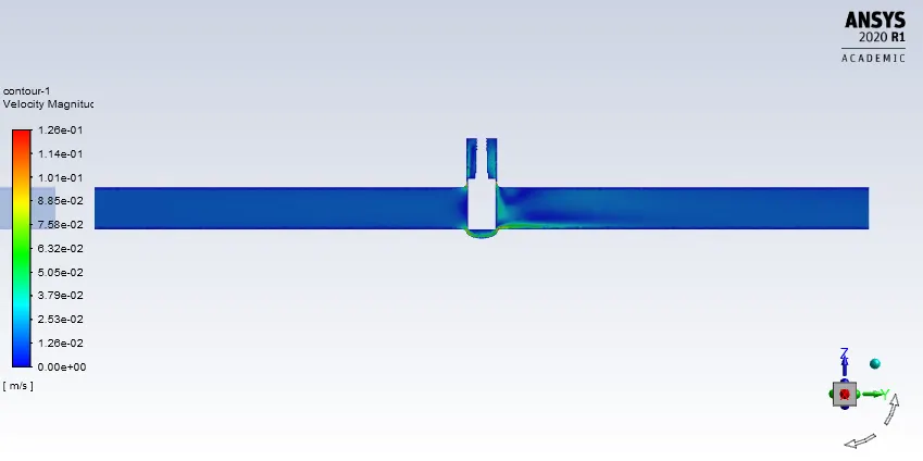
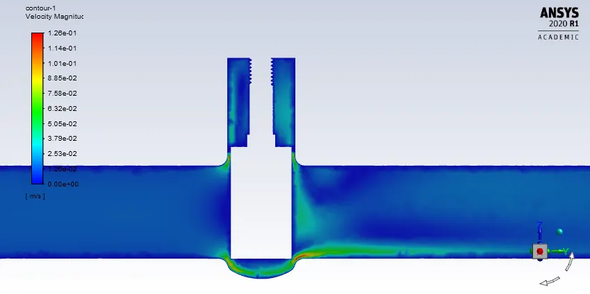
10mm lift
Velocity Contour
Pressure Contour
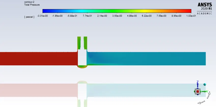
Mass Flow Rate - 0.1490955 kg/s
20mm lift
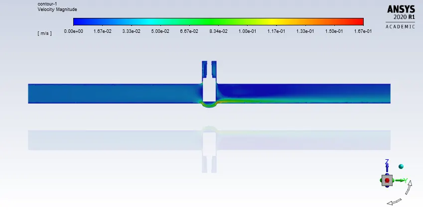
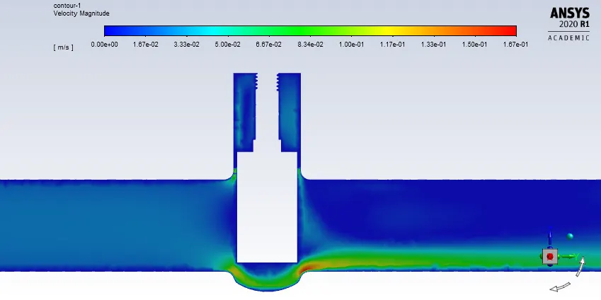
Velocity Contour
Pressure Contour
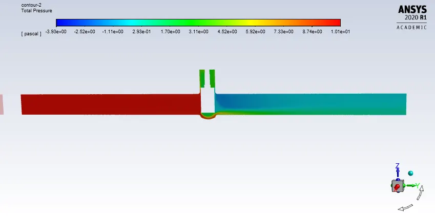
Mass Flow Rate - 0.23890949
30mm lift
Velocity Contour
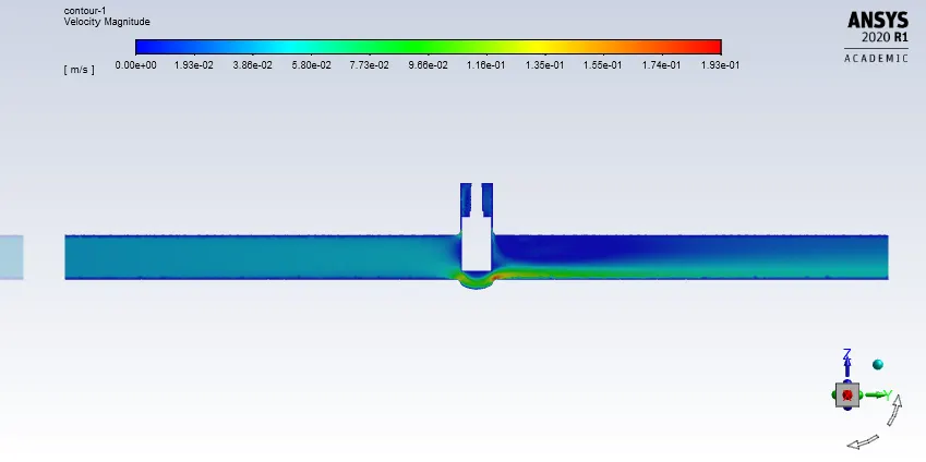
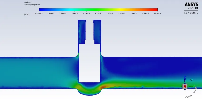
Pressure Contour
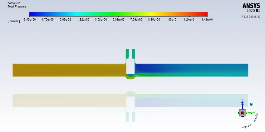
Mass Flow Rate - 0.36225519 kg/s
40mm lift
Velocity Contour
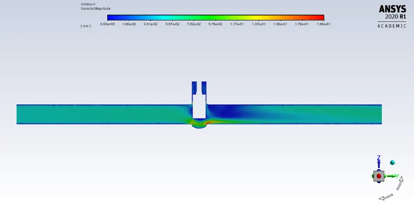
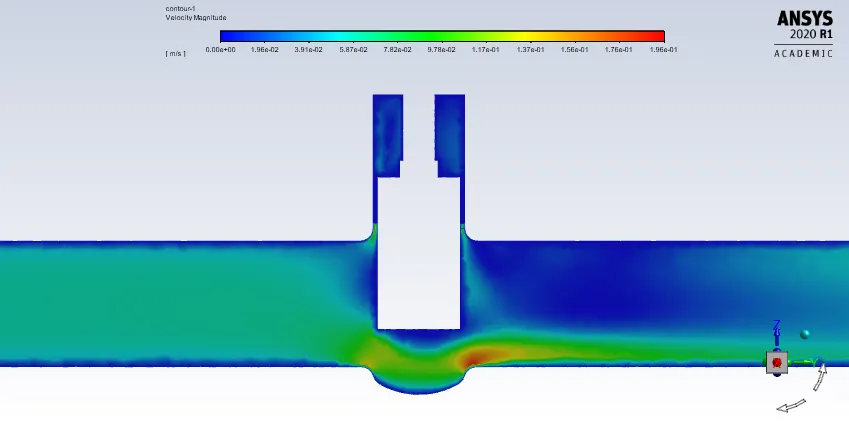
Pressure Contour
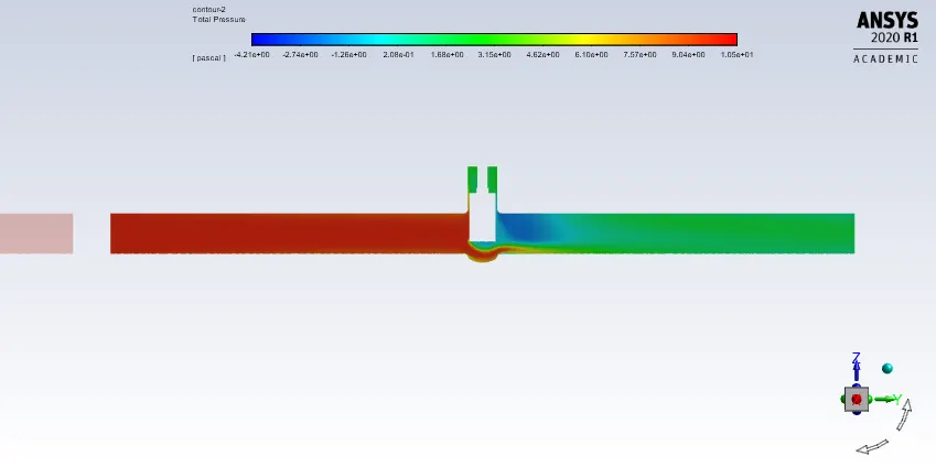
Mass Flow Rate - 0.47272418 kg/s
50mm lift
Velocity Contour
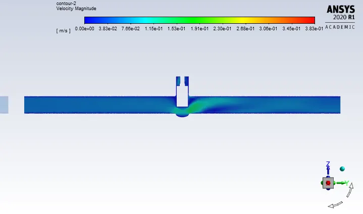
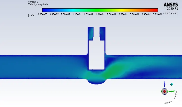
Pressure Contour
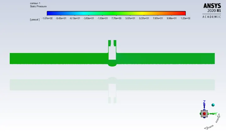
Mass Flow Rate - 0.54772888 kg/s
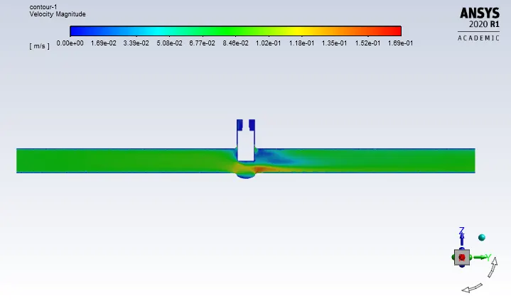
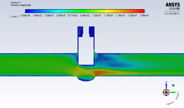
60mm lift
Velocity Contour
Pressure Contour
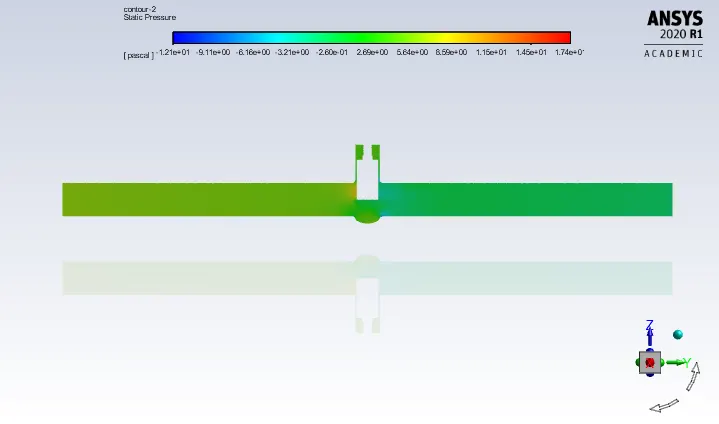
Mass Flow Rate - 0.6413111 kg/s
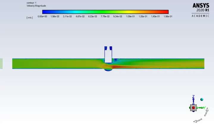
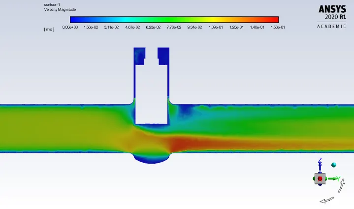
70mm lift
Velocity Contour
Pressure Contour

Mass Flow Rate - 0.71930853 kg/s
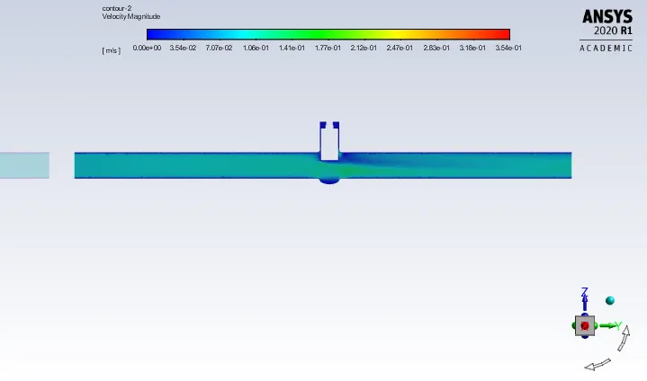
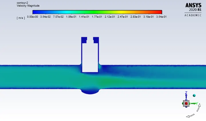
80mm lift
Velocity Contour
Pressure Contour
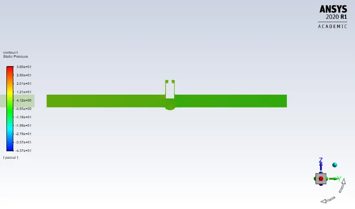
Mass Flow Rate - 0.91050154 kg/s
Parametric Study -
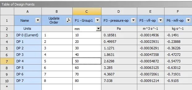
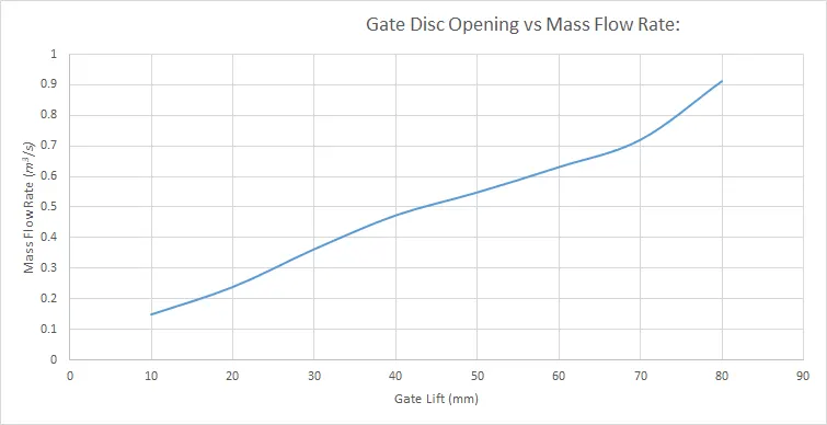
With the different values of gate disc lift, there is a change in pressure and flow rates.
negative value shows the flow is leaving the domain.
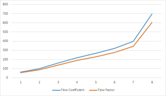
Flow coefficient:- The flow coefficient of a device is a relative measure of its efficiency at allowing fluid flow. The flow coefficient is the volume (in gallons) of water at 60deg F that will flow per minute through a valve with a pressure drop of 1psi across the valve. It is given by the formula,
Where Cv - flow coefficient
Q - volume flow rate ( gallons per minute)
SG - specific gravity of the fluid ( for water = 1 )
dP - pressure drop ( Psi )
Flow factor:- The flow factor is the flow coefficient in metric units. It is defined as the flow rate in cubic meters per hour of water at a temperature of 16deg C with a pressure drop of 1 bar. It is given by the formula,
Where Kv - flow factor
Q - volume flow rate ( m3/hr )
SG - specific gravity of the fluid ( for water = 1 )
dP - Pressure drop ( bar )
| Gate Lift (mm) | Pressure (pa) | Volume Flow rate (m3/s) | Mass Flow rate (kg/s) | Flow Coefficient | Flow Factor |
| 10 | 0.18581105 | -0.000149364 | -0.1490955 | 62.75038 | 54.2790787 |
| 20 | 0.49957252 | -0.000239312 | -0.23888171 | 102.185751 | 88.3906746 |
| 30 | 1.127057 | -0.000362908 | -0.36225519 | 160.346615 | 138.6998219 |
| 40 | 1.8630741 | -0.000473577 | -0.47272418 | 218.5026248 | 189.0047705 |
| 50 | 2.6297659 | -0.000548717 | -0.54772888 | 266.0137094 | 230.1018586 |
| 60 | 3.2849715 | -0.000631253 | -0.63011711 | 320.6094838 | 277.3272035 |
| 70 | 4.3607482 | -0.000720606 | -0.71930853 | 399.3774013 | 345.4614522 |
| 80 | 7.0380202 | -0.000912143 | -0.91050154 | 697.5392647 | 603.371464 |
Conclusion :
- The mass flow rate increases and pressure drops as the gate disc of the valve are lifted higher.
- From the above table, it is observed that the flow coefficient and flow factor increases as the pressure drop across the valve is lowered and the pressure drop decreases as the mass flow rate increases across the valve.