Frequency Analysis of a rotating shaft Using SolidWorks
AIM : To find out the critical frequencies of a rotating shaft in Solidworks.
OBJECTIVES :
- To create 3D model of a rotating shaft.
- To perform frequency analysis on the rotating shaft and find out the critical frequencies.
INTRODUCTION : For a rotating shaft there is a speed at which, for any small initial deflection, the centripetral force is equal to the elastic restoring force. At this point the deflection increases greatly and the shaft is said to "whirl". Below and above this speed this effect is very much reduced. This critical (whirling speed) is dependent on the shaft dimensions, the shaft material and the shaft loads . The critical speed is the same as the frequency of traverse vibrations. The critical speed Nc">NcNc of a shaft is simply,
Nc=km2π">Nc=√km2πNc=km2π ,where m">mm = the mass of the shaft assumed concentrated at single point . k">kk is the stiffness of the shaft to traverse vibrations.
For a horizontal shaft this can be expressed as,
Nc=gy2π">Nc=√gy2πNc=gy2π ,where y">yy = the static deflection at the location of the concentrated mass. g">gg is acceleration due to gravity.
THEORY : Consider a rotating horizontal shaft with a central mass (m) which has a centre of gravity (G) slightly away from the geometric centroid (O),
The centrifugal force on the shaft =mω2(y+e)">=mω2(y+e)=mω2(y+e) and the inward pull exerted by the shaft =y(48EIL3)">=y(48EIL3)=y(48EIL3).
The more general formula for the restoring traverse force of the beam is y(KEIL3)">y(KEIL3)y(KEIL3) where K">KK = 'a constant depending on the position of the mass and the end fixing conditions'.
Equating these forces,
⇒">⇒⇒
When the denominator =0">=0=0 ,that is [KEImω2L3]=1">[KEImω2L3]=1[KEImω2L3]=1, the deflection becomes infinite and whirling takes place.
The whirling or critical speed is therefore,
⇒">⇒⇒ωc=KEImL3">ωc=√KEImL3ωc=KEImL3 ,
Substituting ωc2">ω2cωc2 for KEImL3">KEImL3KEImL3 in the above equation for y">yy results in the following equation which relates the angular velocity with the deflection,
⇒">⇒⇒y=ω2⋅eωc2-ω2">y=ω2⋅eω2c−ω2y=ω2⋅eωc2-ω2,
This is plotted here,
This curve shows the deflection of the shaft (from the static deflection position) at any speed ω">ωω in terms of the critical speed. When ω<ωc">ω<ωcω<ωc the deflection y">yy and e">ee have the same sign that is G lies outside of O. When ω>ωc">ω>ωcω>ωc then y">yy and e">ee are of opposite signs and G lies between the centre of the rotating shaft and the static deflection curve. At high speed G will move such that it tends to coincide with the static deflection curve.
PROCEDURE :
- Geometry Modelling of a Rotating Shaft -
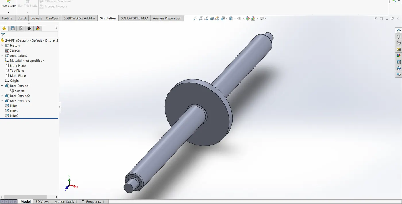
- At first, a shaft and a disc were sketched and then assembled to form a rotating shaft assembly. For sketching shaft, there can be multiple ways, i.e., either circle can be drawn and extruded or a line of the desired length is sketched and revolved around its axis to form a shaft. Here the First one is used.
- The Multiple circles have been drawn with different diameter and accordingly extruded up to the desired length for the shaft.
- Drawing -
- Extrude -
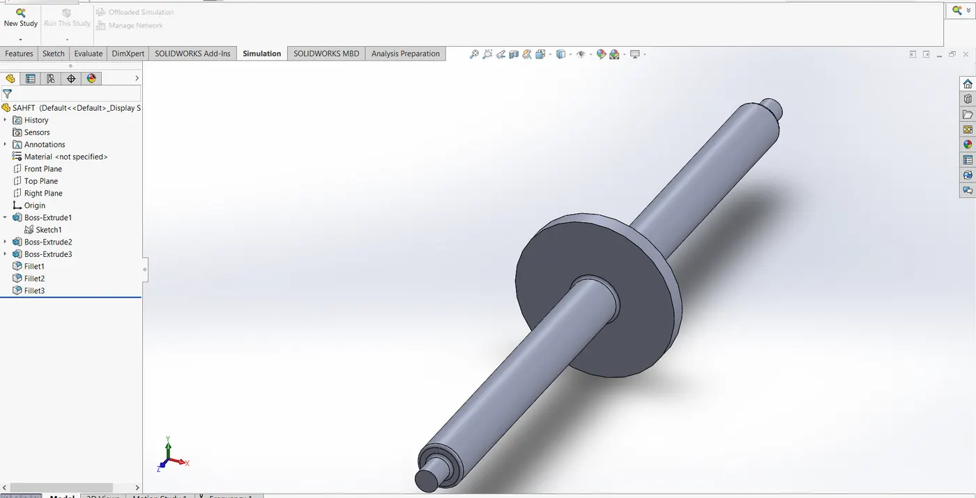
- Assembly of Rotating Disc -
- For assembly of these component, they were inserted in the assembly window and mated accordingly.
- Simulation Setup -
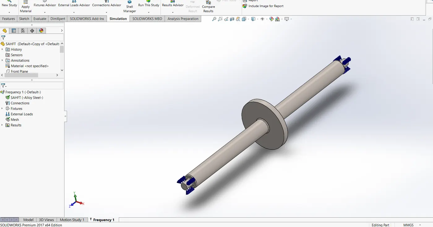
For frequency analysis, Solidworks Simulation was setup. Here frequency analysis was carried out for "Alloy Steel (SS )"Bearing fixtures were provided at the two stepped faces of the shaft at the two ends . The properties of 'Alloy Steel (SS)' are as follows :-
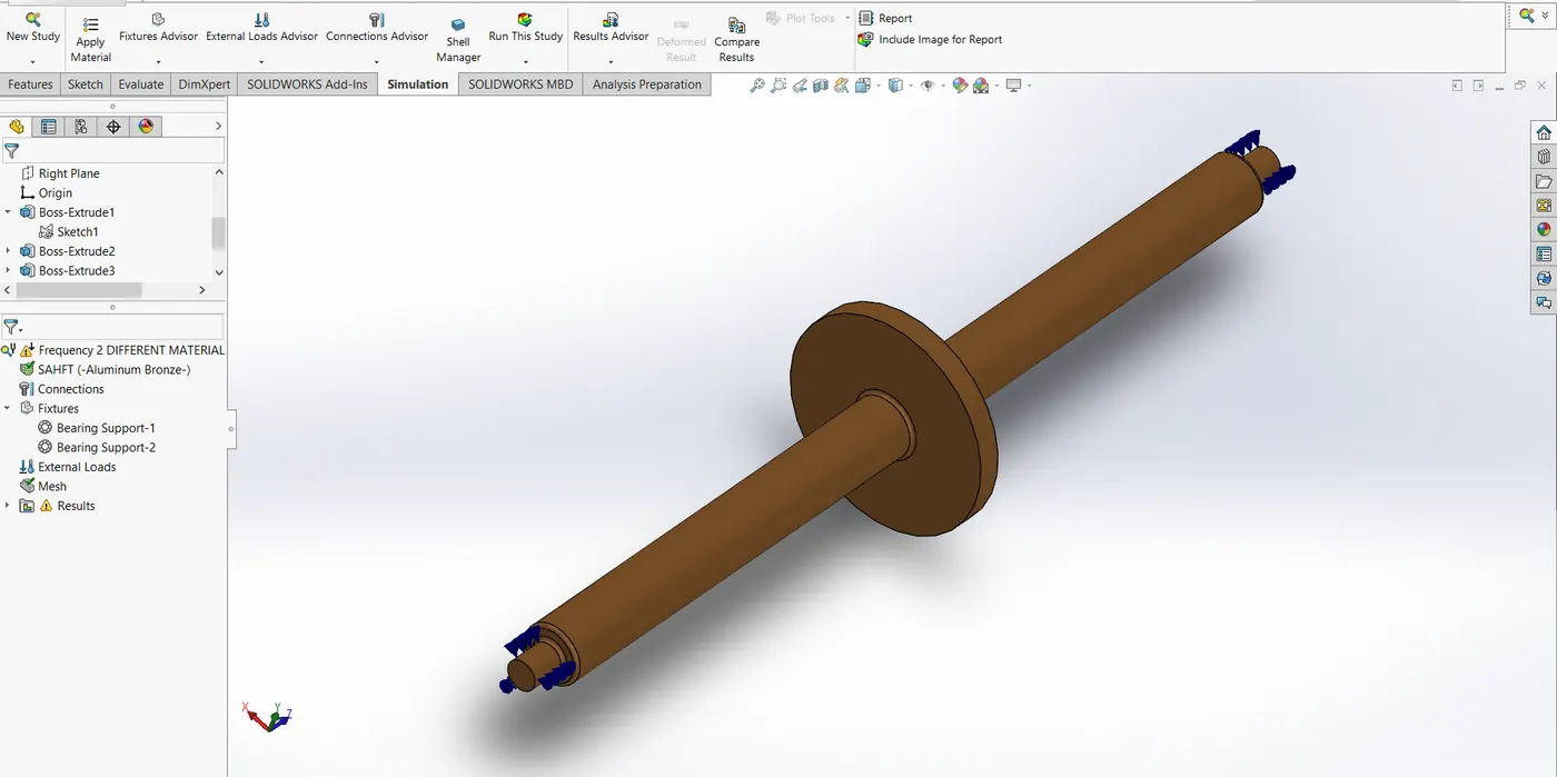
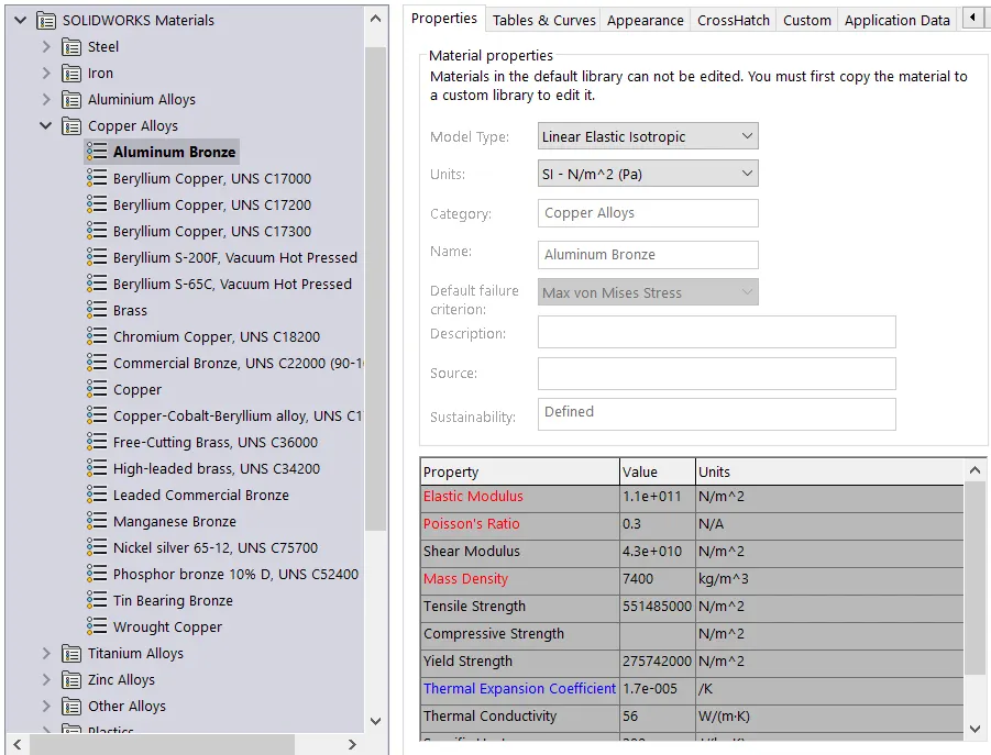
For frequency analysis, Solidworks Simulation was setup. Here frequency analysis was carried out for "Aluminum Bronze"Bearing fixtures were provided at the two stepped faces of the shaft at the two ends . The properties of 'Aluminum Bronze' are as follows :-
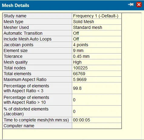
- Meshing were done on the part bodies for simulation. The global mesh size was set to 9mm"> 9mm7.5mm and the simulation was made to run. The properties of meshing are,
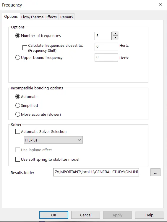
- The study settings were kept as default setting. The number of mode shapes were kept as 5">55 and rest of settings can be viewed here,
RESULT :
CASE STUDY 1 : -
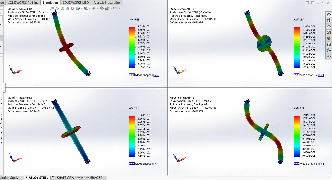
- Frequency Analysis for 'Alloy Steel (SS)' ,
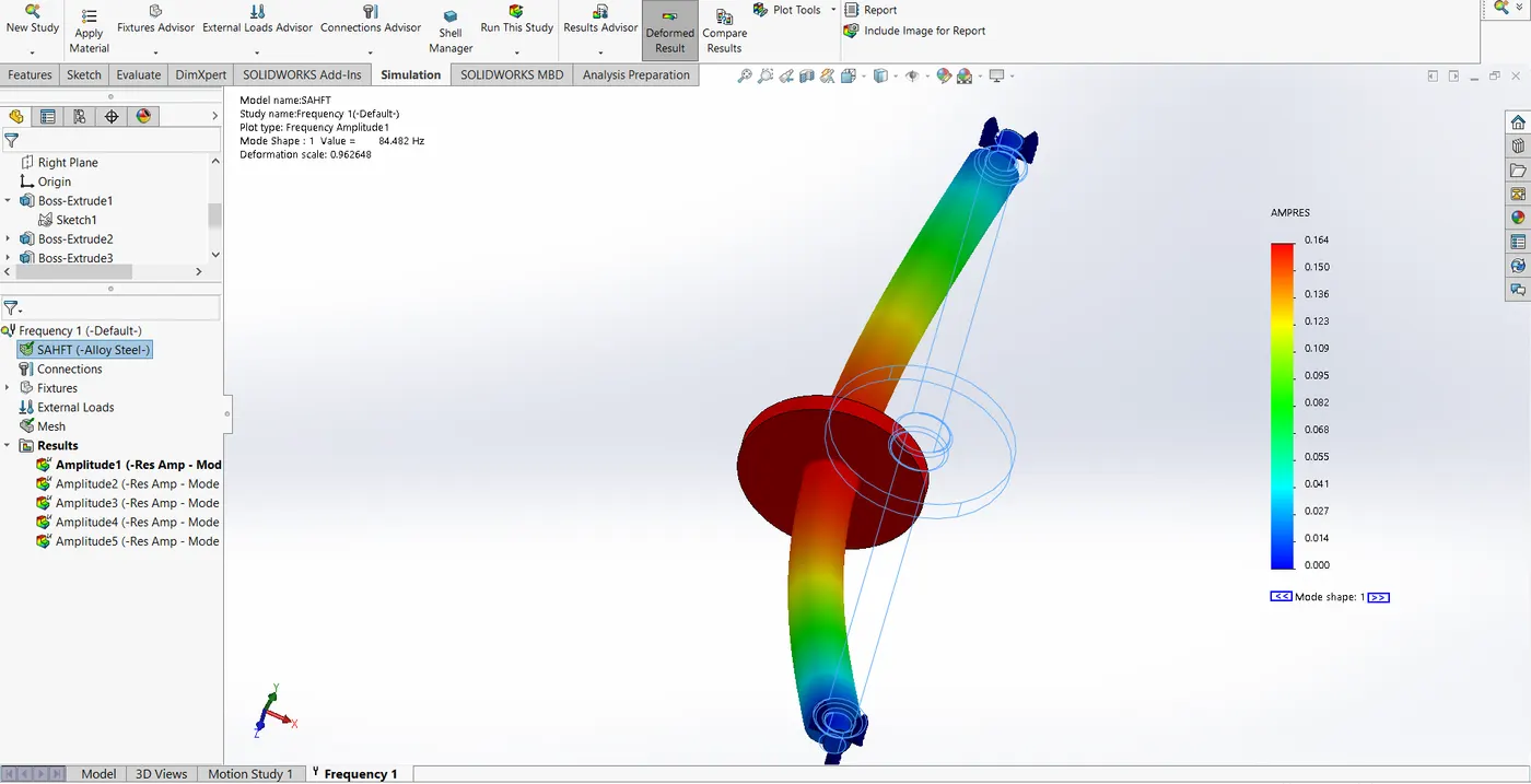
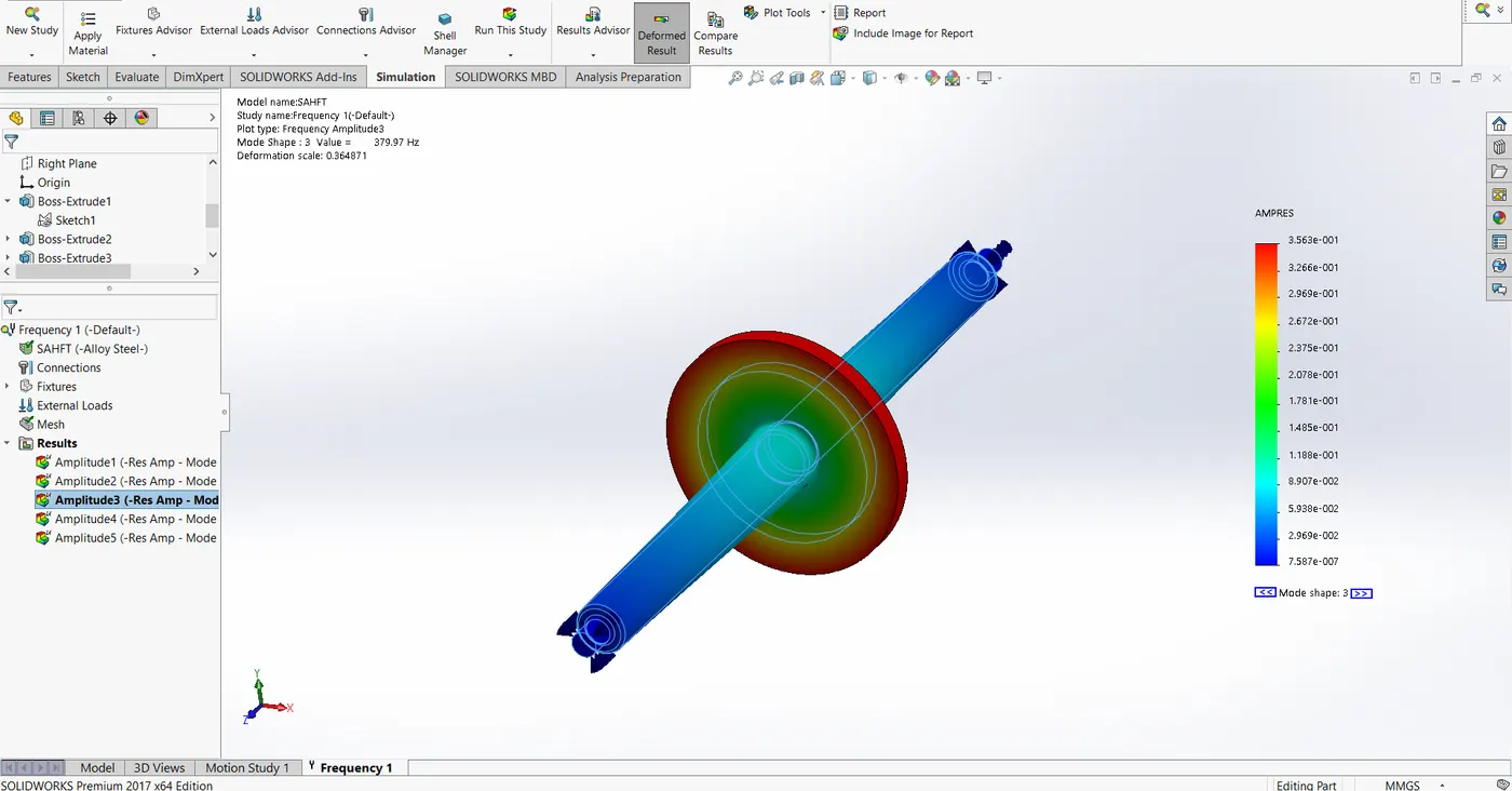
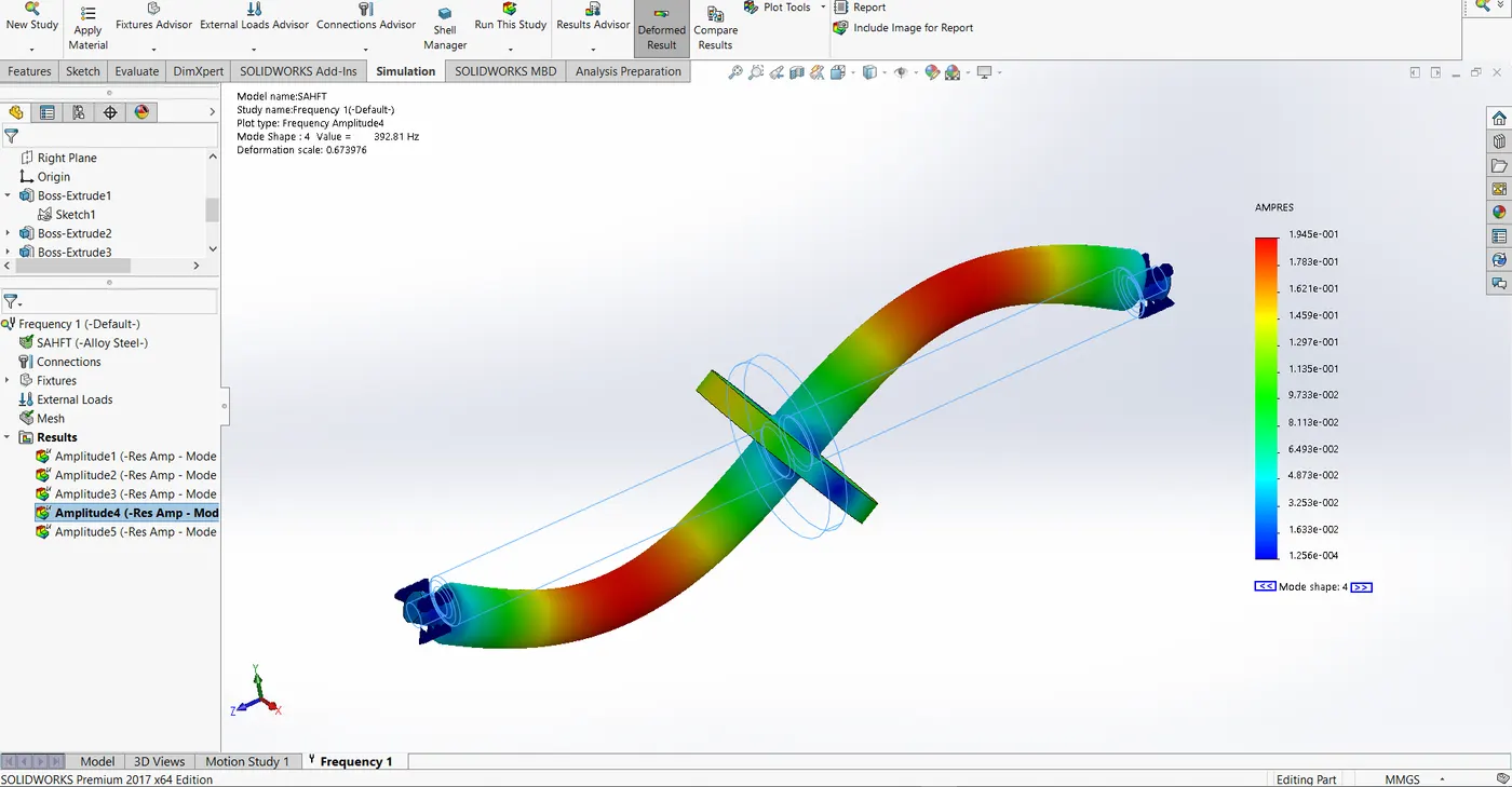
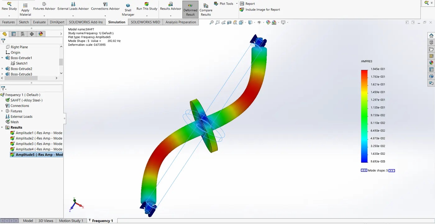
- The study was carried out for 5">55 mode shapes, and amplitudes for each study was observed.
- Mode Shape 1 :
- Mode Shape 2 :
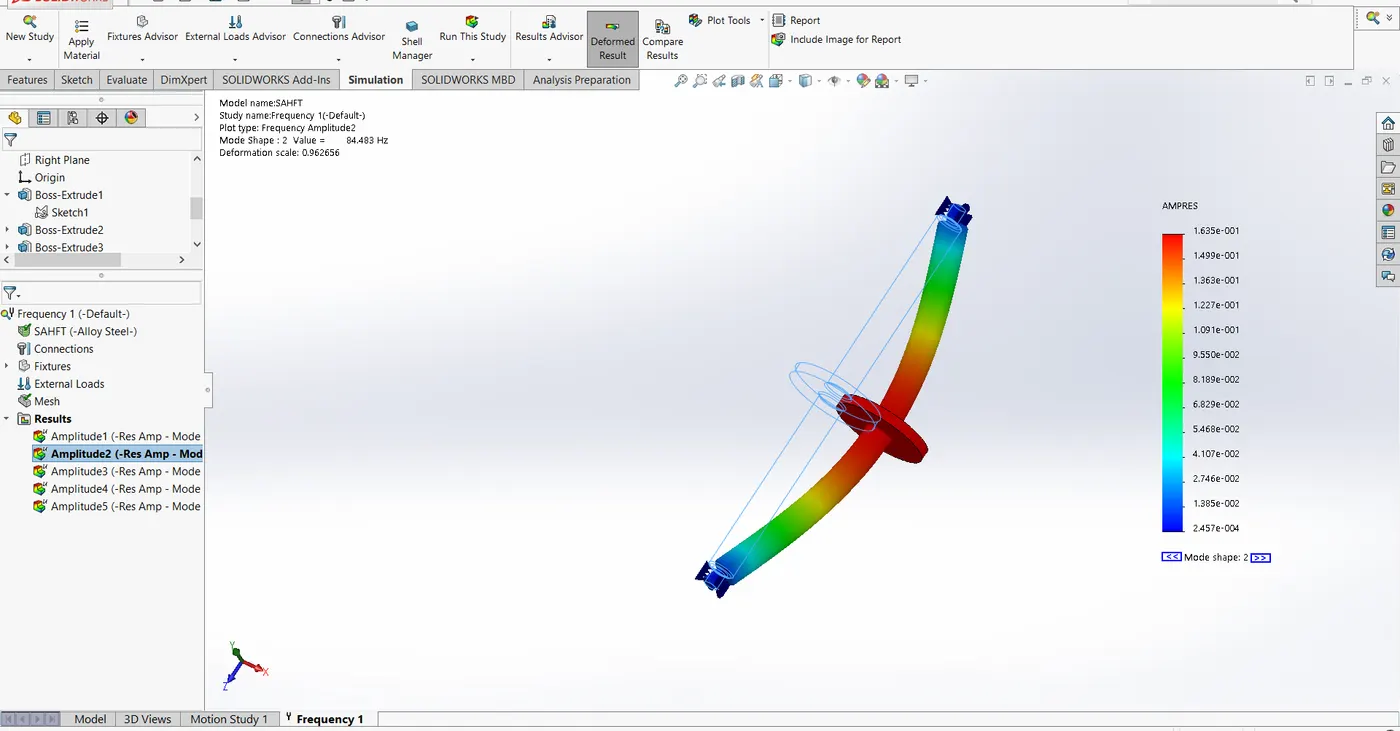
- Mode Shape 3 :
- Mode Shape 4 :
- Mode Shape 5 :
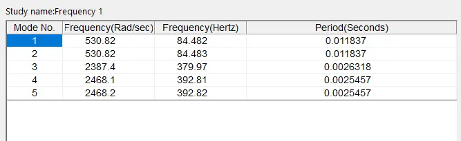
- List of Resonant frequencies :
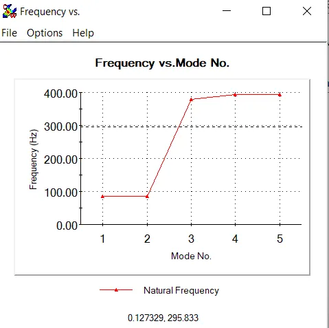
- Plot for Frequency versus Mode number :
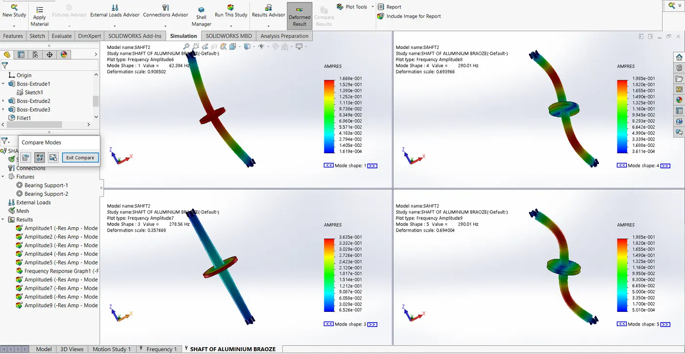
- Case 2. : Frequency Analysis for 'Aluminium Bronze' ,
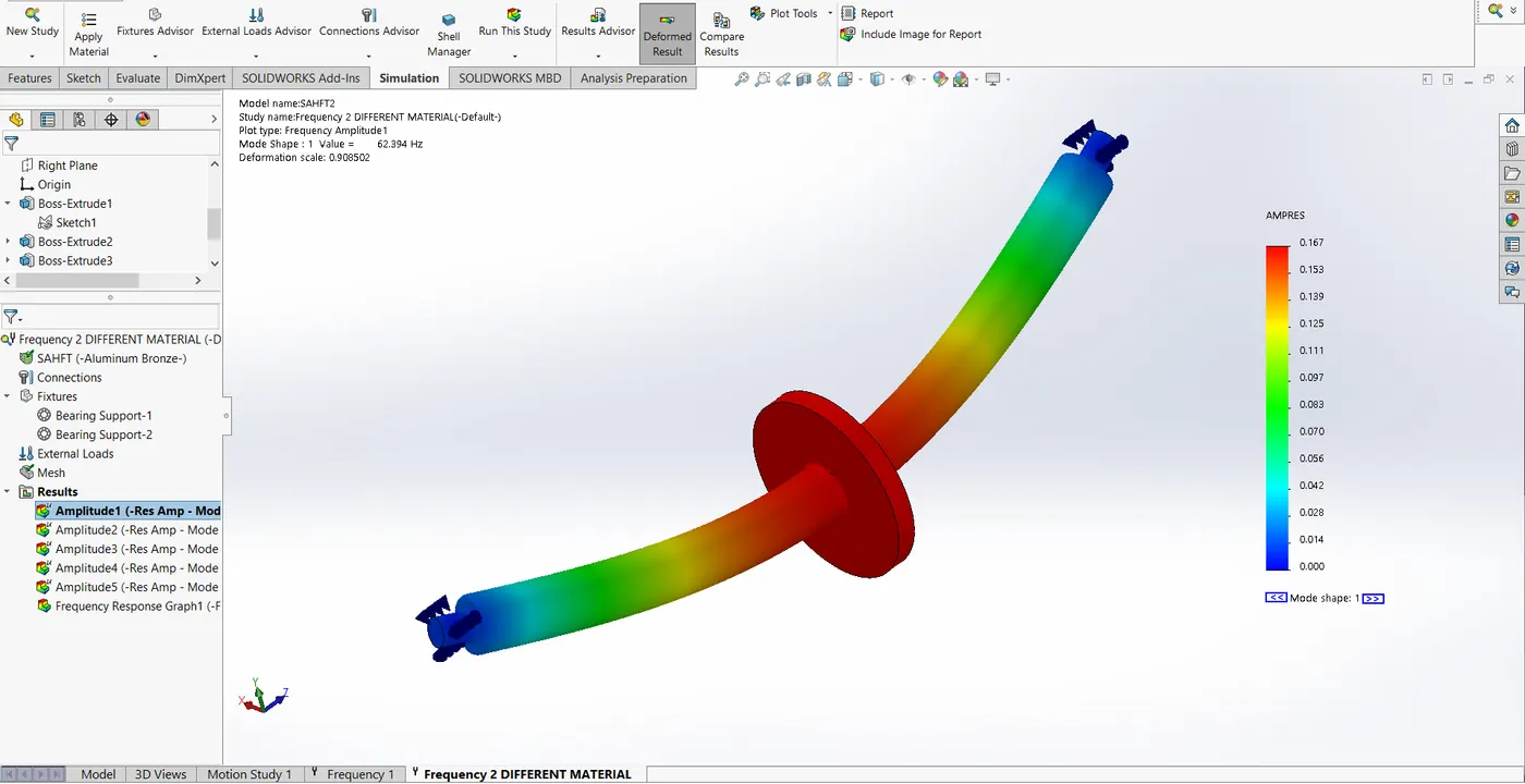
- The study was carried out for 5">55 mode shapes, and amplitudes for each study was observed.
- Mode Shape 1 :
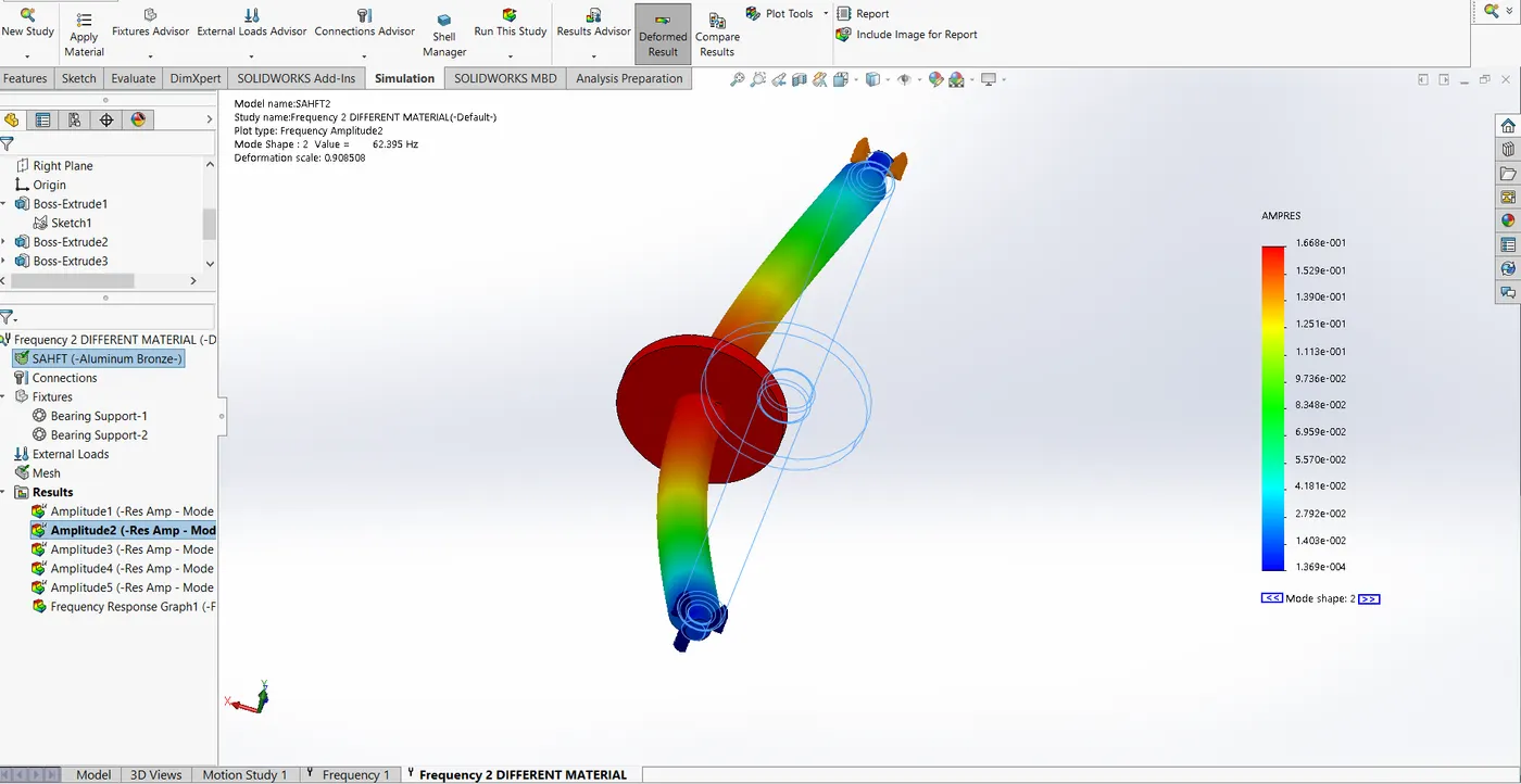
- Mode Shape 2 :
- Mode Shape 3 :
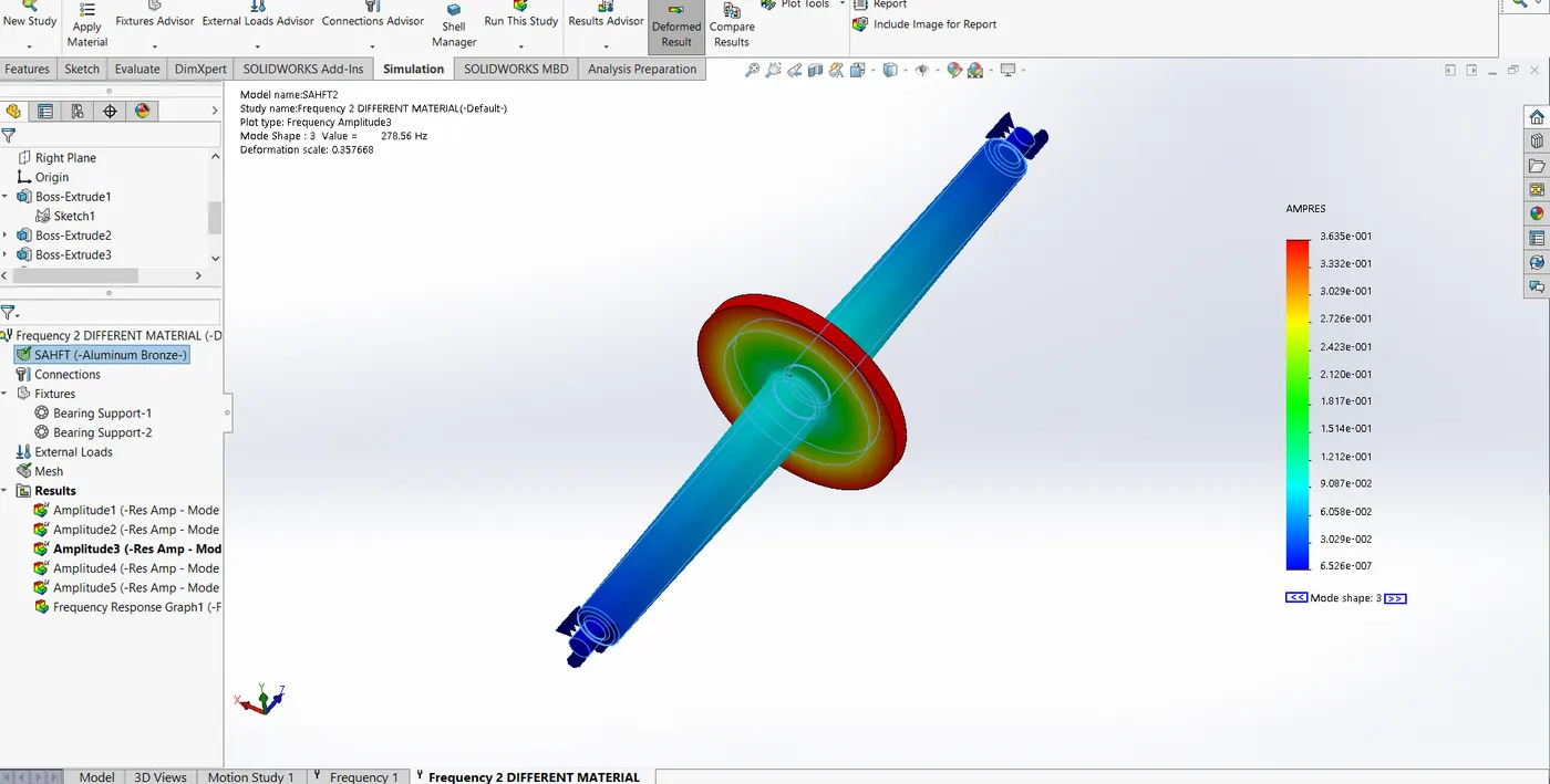
- Mode Shape 4 :
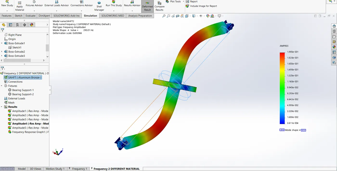
- Mode Shape 5 :
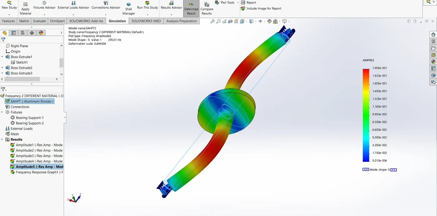
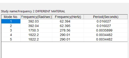
- List of Resonant frequencies :
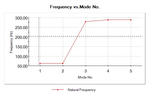
- Plot for Frequency versus Mode number :
- Comparison between both materials for different modes-
CONCLUSION :
- From the result obtained for 'Alloy Steel (SS)' , it can be concluded that the above system has resonant frequencies at 84.82 Hz, 379.97101.33Hz, 392.81480.78Hz.
If the above system is made to run at or near the resonance frequencies, Whirling of shafts occurs due to rotational imbalance of a shaft, even in the absence of external loads, which causes resonance to occur at certain speeds, known as critical speeds. Whirling speed is also called a Critical speed of a shaft. It is defined as the speed at which a rotating shaft will tend to vibrate violently in the transverse direction if the shaft rotates in the horizontal Plane. In other words, the whirling or critical speed is the speed at which resonance occurs. - Similarly from the result obtained for 'Aluminium Bronze', it can be concluded that the above system has resonant frequencies at 62.3940.0676Hz , 278.5698.71Hz , 290.01465.51Hz.
If the above system is made to run at or near the resonance frequencies, there is a chance of failure of the structure due to Whirling of shaft. The system will work fine for all other frequencies` - To avoid the effect of resonance, the system can be incorporated with dampers or springs. Two movable nylon bushes also help to prevent the shaft whirling amplitude from reaching excessive levels.
- The material should be selected carefully for designing such systems as different materials can have different resonant frequencies and such materials should be selected which have high natural frequencies as it can be concluded that Alloy Steel system have higher resonant frequencies as compared to Aluminium Alloy. They can be employed for their purposes according to requirement.
REFERENCES :
- Sarangarjan VijayraghavanVery detailed report Sourabh. I learned a lot from this. Nice work!