Foundation Design using SAFE
AIM -
1. Model the isolated footing provided in the week 11 challenge on SAFE. Analyze and design it to verify the size, depth, and steel provided as per calculations.
ANS -
Modeling the square isolated footing provided in week 11 on safe.
following condition having isolated footing is.
1. Square footing for a column size 400x400.
2. compression axial load for the load combination of (1.5 dl +1.5 Ll ) is 2000 kn.
3. The Safe soil bearing capacity is 150 kn/`m^2` at a depth of 2 meters below E.G.L
Assume, M25 concrete grade
density of the soil is 20 kn/cum.
The following data is required for safe design and analysis.
1. Unfactored load = compression axial load/surcharge pressure of the soil.
= 2000 / 1.54 = 1333.3 kn.
2. dead load breakup = 1333.3/2 = 666.7 kn.
3. live load breakup = 1333.3/2 = 666.7 kn.
4. Subgrade modulus for soil = (safe bearing capacity of soil*factor of safety)/ allowable permissible stress.
= 150 x 3 / 0.05
= 9000 kn/`m^3`
5. Rebar yield strength (y) = 500 N`mm^2`
6. Rebar Ultimate Strength (fu) = 575 N`mm^2`
7. Elastic modulus of M25 concrete is = 5000 x `root`fck
= 5000 x `root`25
= 5000 * 5
= 25000 N/`mm^2`
Safe Design
open a new model. and select on a single footing.
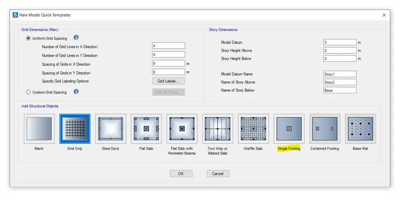
after clicking on the single footing it will open a new window in that window.
filling the following thing.
1. dead + live load = 666.7 kn.
2. Along x and y directions putting half the area of the footing which is 1.8m.
3. footing slab thickness = 500 mm
4. soil subgrade modulus = 9000 kn.
5. column square size = 400 mm
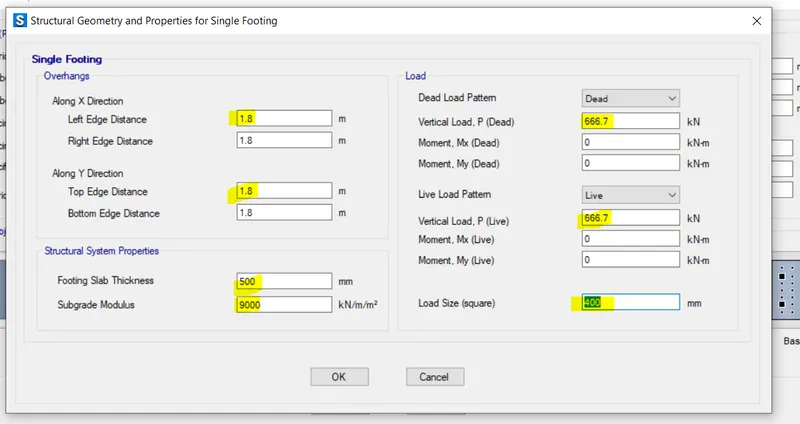
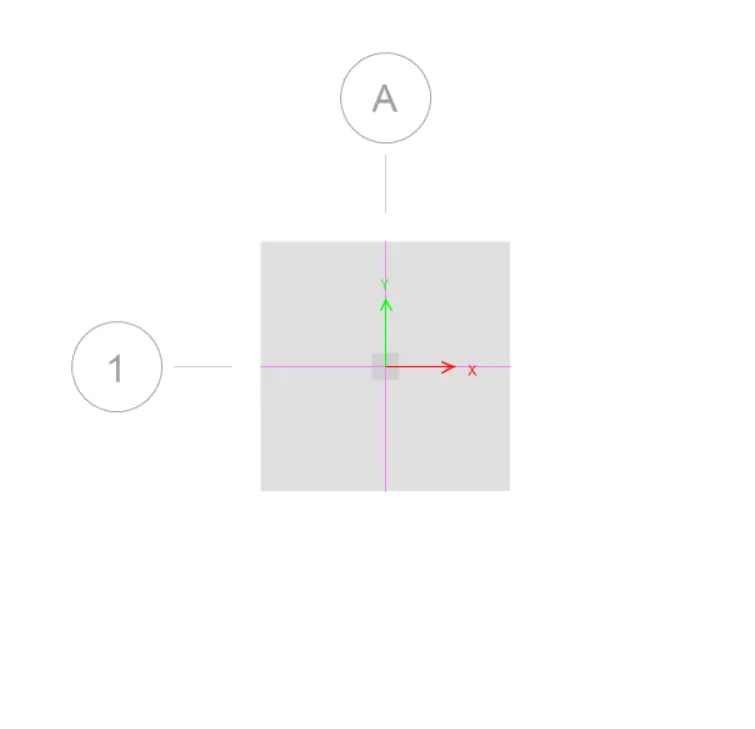
click on. ok after that it opens a created single footing.
Define Material
For Define the material selects a define option after that select a material section.
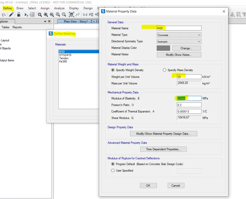
1. M25 concrete Grade -
create m25 grade from defined material option and after that select weight per unit volume 25 kn/`m^3`
and select a modulus of elasticity 25000 mpa which is coming from young modulus.
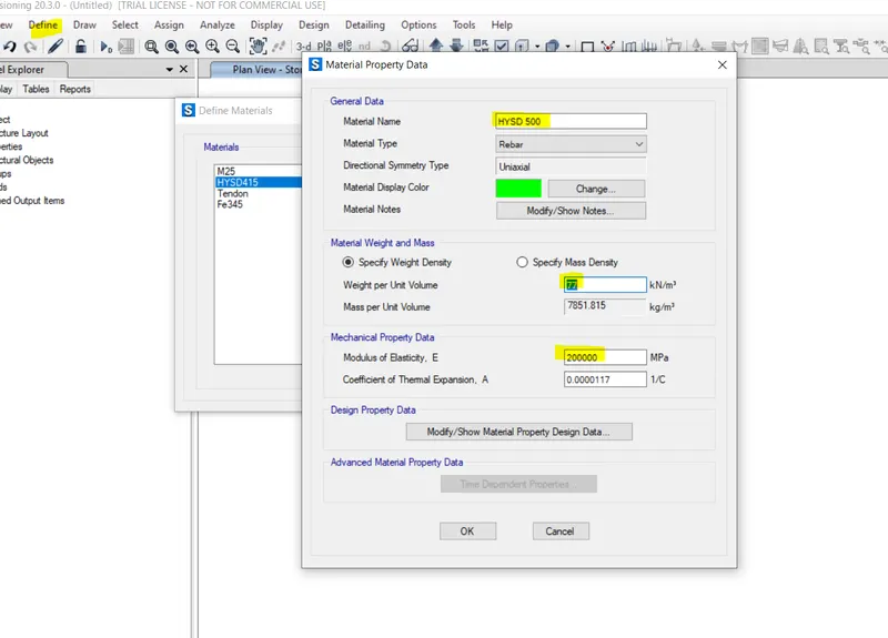
2. Fe 500/ HYSD 500 =
Selecting fe500 steel rebar for footing and select modify rebar and select 77 kn/`m^3` waight per unit volume. after that select modulus of elasticity is 200000 mpa.
Define Slab Section
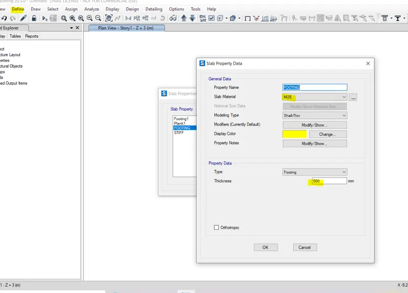
1. footing -
Define the slab section of the footing and select the thickness of the footing. and select a slab material as an m25.
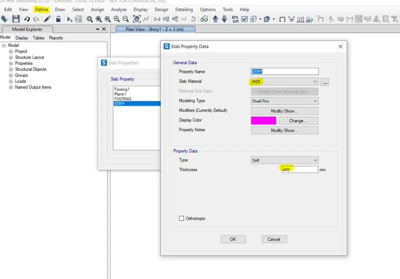
2. Stiff -
use the same process as we use for the footing adding the thickness of the footing is 400. and after that select type as a stiff, and selecting a grade of the concrete is m25.
Soil Sub garde Modulus
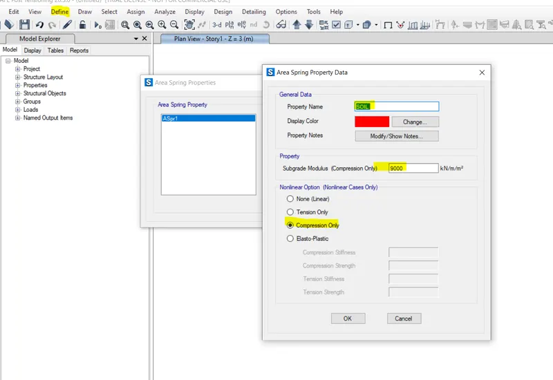
soil subgrade modulus in software is called as an area of spring.
1. Soil subgrade modulus / Area of spring =
To add Area of spring select the define option and after that Area of spring from the spring property.
select property name soil1. select subgrade modulus compression is 9000 kn/`m^2`. after that select nonlinear option is compression only.
Load Cases
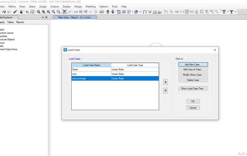
1. load cases - selecting a linear static load cases which is dead load, live load, after that adding soil surcharge
Load Combination
1. Load Combination -
use three linear static load combinations which is combo 1 ( dead +soil surcharge ), combo 2 ( dead + live + soil surcharge ), and third one is settlement ( dead + live load )
Run the Analysis
select a Run analysis play and start an analysis.
Checks -
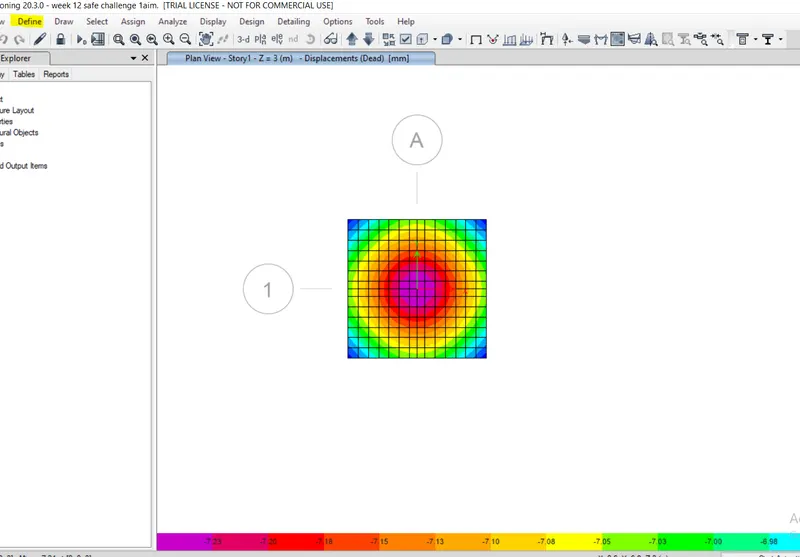
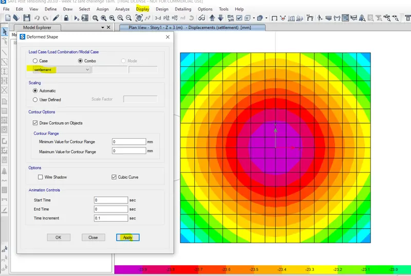
1. settlement under serviceability load -
click on deformed shape after that. select settlement from combo and click on apply.
2. two way shear check ( punching shear ) -
checking two-way punching shear select a punching shear from the ribbon.
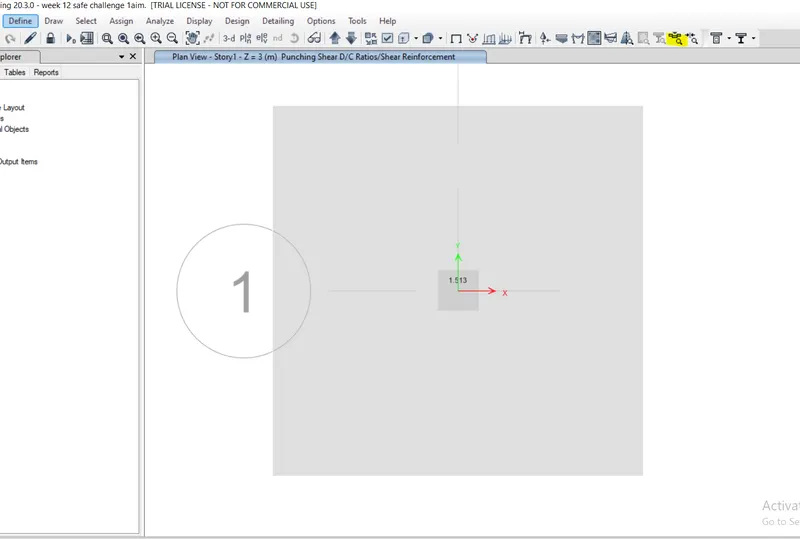
3. Ultimate bending moment - click both strips and select the design strip located in the top of the ribbon.
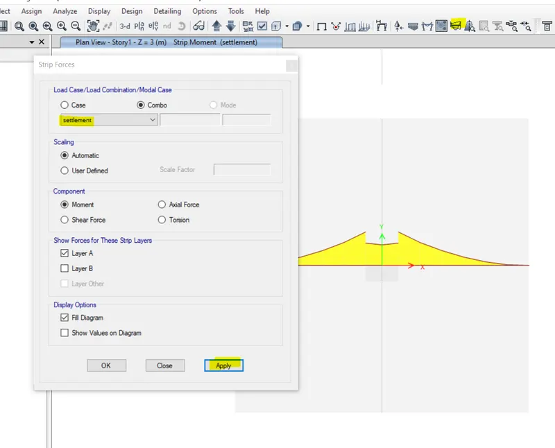
layer A
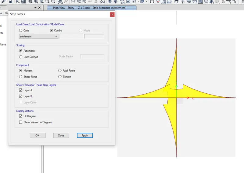
layer A and B
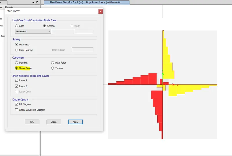
shear force
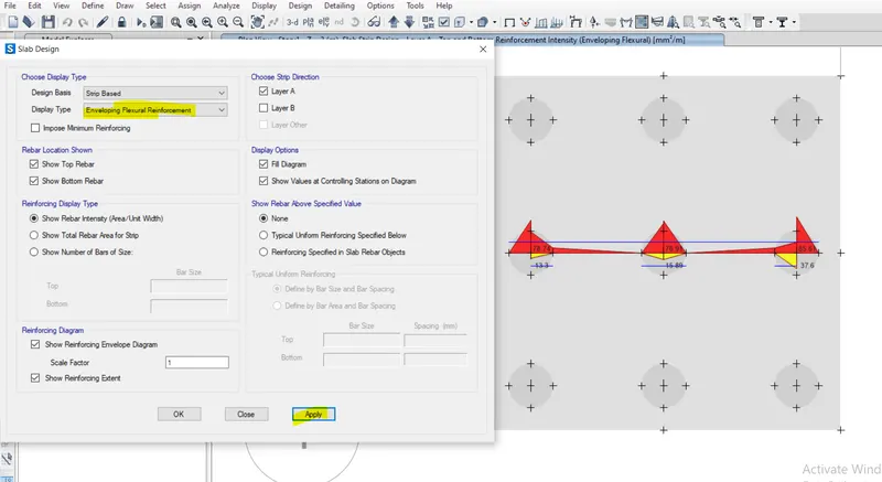
4. Flexural reinforcement design for footing slab -
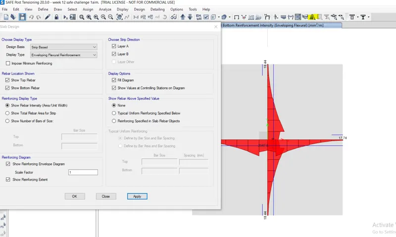
click on show slab design click apply it shows the flexural reinforcement design.
AIM - 2
2. A column of size 600x600 carrying an unfactored gravity load (DL+LL) of 1175 KN is to be supported on pile cap, which ultimately transfers the load to the piles underneath. Piles of 16 meters length and 500 mm diameter are to be used. Each pile has a load-carrying capacity of 200 KN. Model, analyze and design the pile cap on SAFE to evaluate the following:
- Pile group to be used
- Depth of pile cap
- Longitudinal steel on top and bottom face in both directions
ANS - The following thing is given on the aim.
1. column size - 600x600
2. unfactored gravity load - 1175 kn.
3. pile having a diameter -500mm
4. pile length - 16 m.
5. load carrying capacity - 200 kn.
dead load breakup - 1175/2 = 587.5 kn.
live load breakup - 1175/2 = 587.5 kn.
point spring of pile - A x E / L
- 196349 * 25000 / 16000 = 306796 KN/M.
K FOR Safe analysis - 306.8 kn/m
Rebar yield strength (fy) = 500 n/mm2
Rebar ultimate strength (fu) = 575 n/mm2
Elastic modulus of m25 concrete = 25000 n/mm2
Required no. of piles = unfactored load with the addition of self-weight / individual pile cap[acity
= 1175 x 1.1 /200
= 6.5
considering 8 piles. for symmetric placement.
take the center-to-center distance between pile = 3 x pile diameter ( 1500 )
Edge distance from pile center = 1 x pilr diameter ( 500mm)
assume pile cap depth - 500 mm
Safe Design
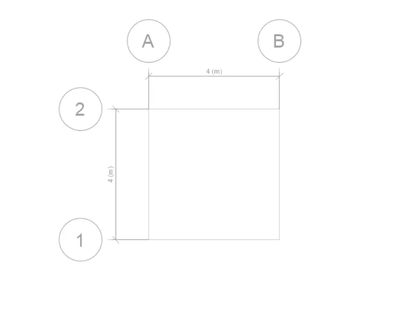
open a new model - select a 4 x 4 pile area from the x and y direction. and click on ok.
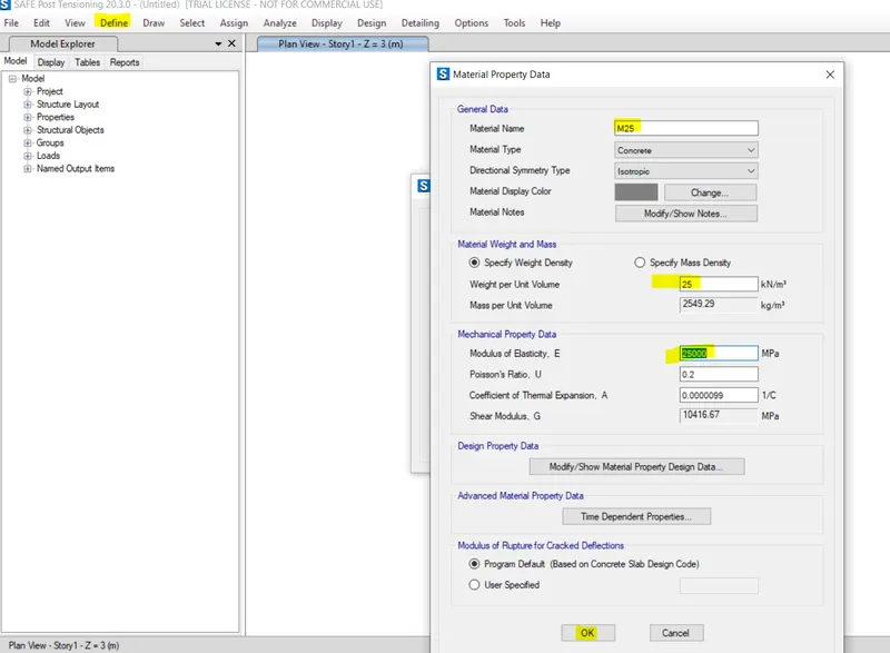
2. Define Material - Defining a material M25 concrete. set weight per unit 25. set modulus of elasticity is 25000. select ok
2. Define Rebar -
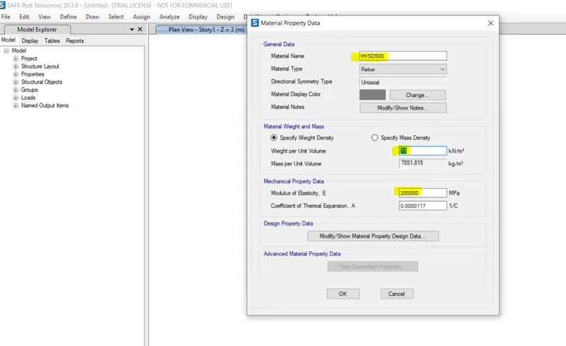
defining material from rebar and add weight per unit volume is 77 kn/m3. modulus of elasticity is 200000 mpa.
Defining Slab Property
1. pile cap -
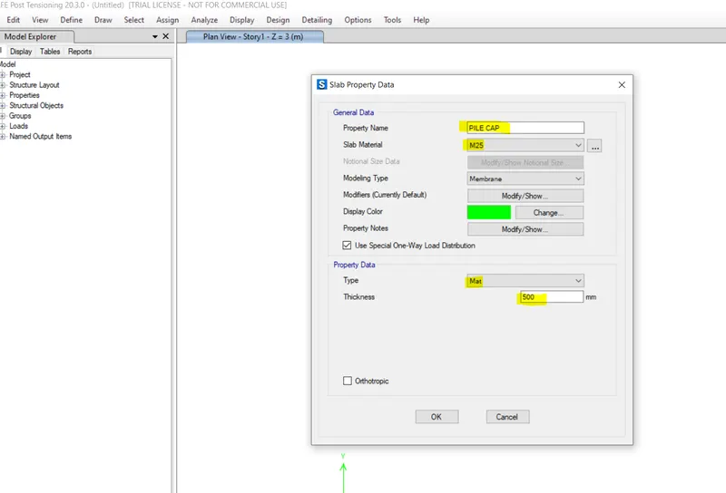
Define pile cap as a mat and provide m25 material and after select type as a mat add thickness is 500mm
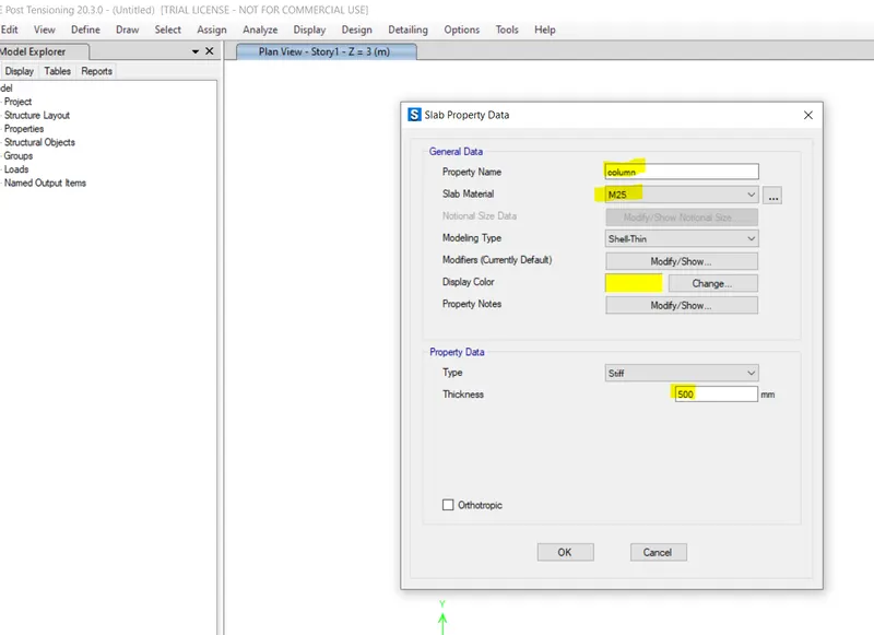
2. Column - select a column as a stiff. and adding m25 as the same thickness 500mm.
3. PILE -
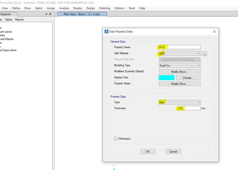
Rename a pile and after that select thickness of a pile is 500 use m25 grade of concrete select type as mat.
Geometric Modelling
1. slab -
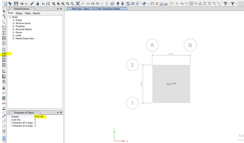
drawing the slab select a draw rectangular tool and after that select a property as a pile cap and after that drawing a slab area.
2. Add The piles -
before adding the piles need to draw the reference point of the pile which center point of the piles.
drawing the reference point from the corner point which is 500 in x and 5000 in y direction.
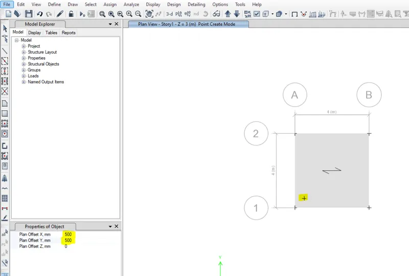
setting next point -
for setting the next pile set a distance between two pile. which is 1500mm in an x direction and after that create a two reference point
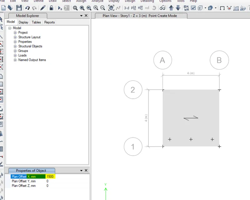
setting second and third row -
continuously selecting a reference point from the last point and after that complthe ete total remaining refrence point of the pile.
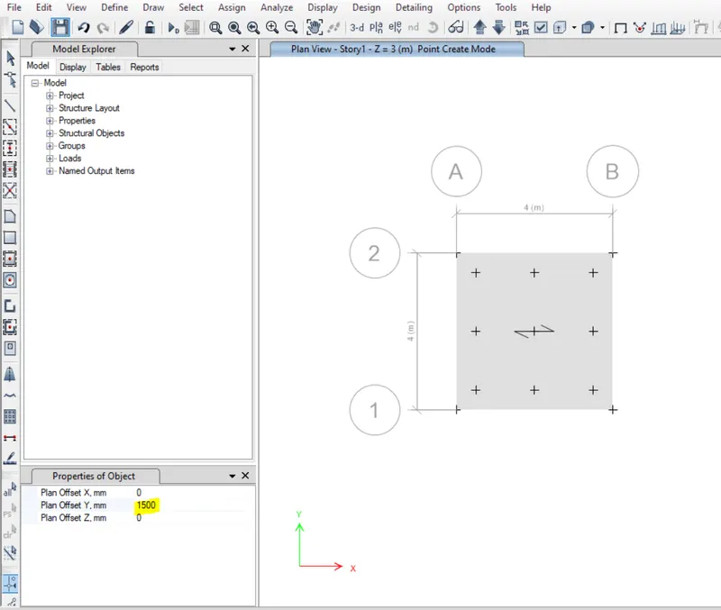
2. Draw the piles -
for drawing the pile select draw around the point and after that select shape of object as circular. and after that property is pile 500 dia. after that diameter is 500 dia. and select a center reference point of the pile.
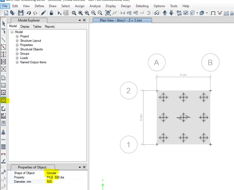
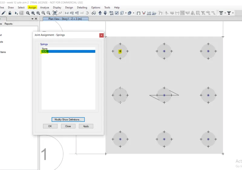
3. Assign Point Spring - Assign point spring which coming from a calculation from EA/L - 306.8KN/M
4. Assign dead load - assign 523 kn dead load.
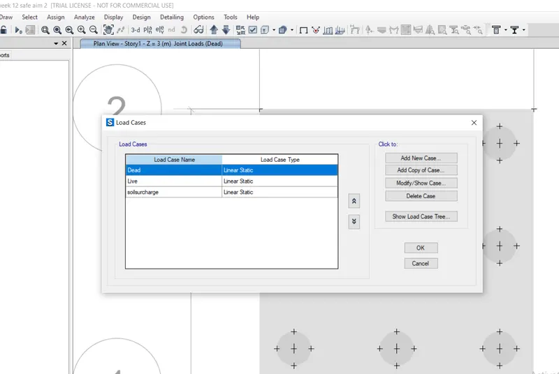
3. load cases - define load ccaseslike dead load, live load, and soil surcharge.
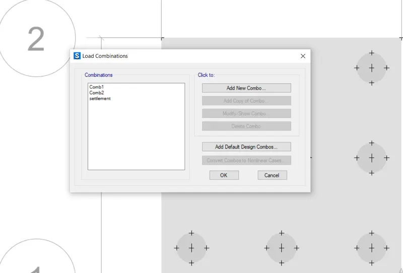
4. load combination - define three load combinations. it is the set of live dead and settlement.
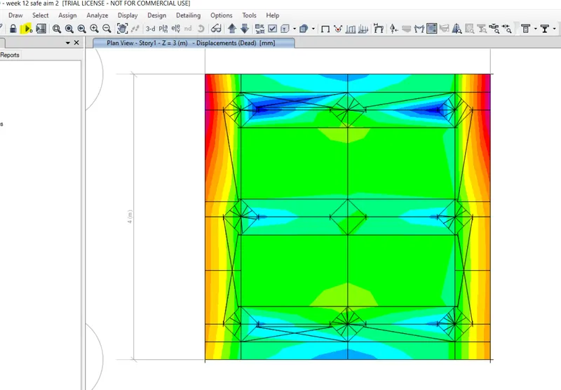
5. Analysis - After defining the load combination select play to start the analysis.
6. Two-way shear check ( punching shear ) -
checking two-way punching shear select a punching shear from the ribbon.
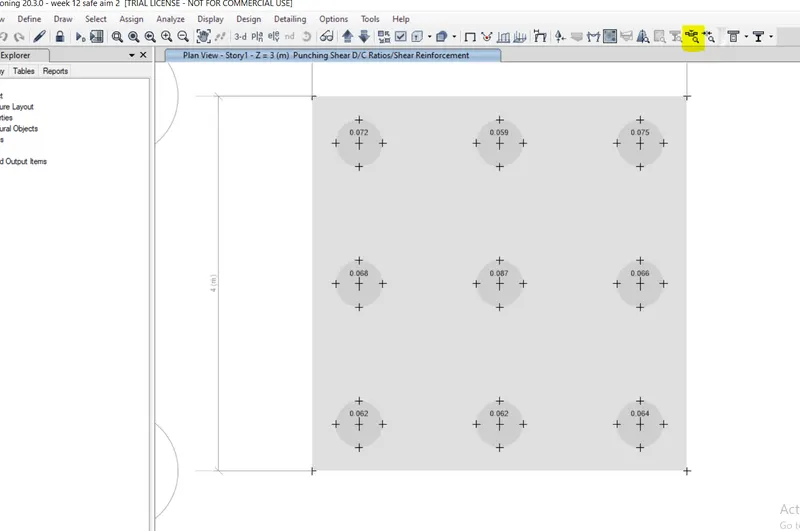
7. Ultimate bending moment - click both strips and select the design strip located at the top of the ribbon.
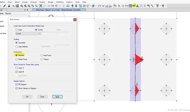
layer A and B
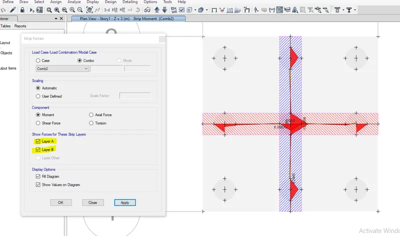
8. Flexural reinforcement design for footing slab -
click on show slab design click apply it shows the flexural reinforcement design.