Foundation Design using SAFE
AIM: To Analyze and design the isolated footing from week 11 challenge on SAFE to verify the size, depth and steel provided as per calculations.
PROCEDURE:
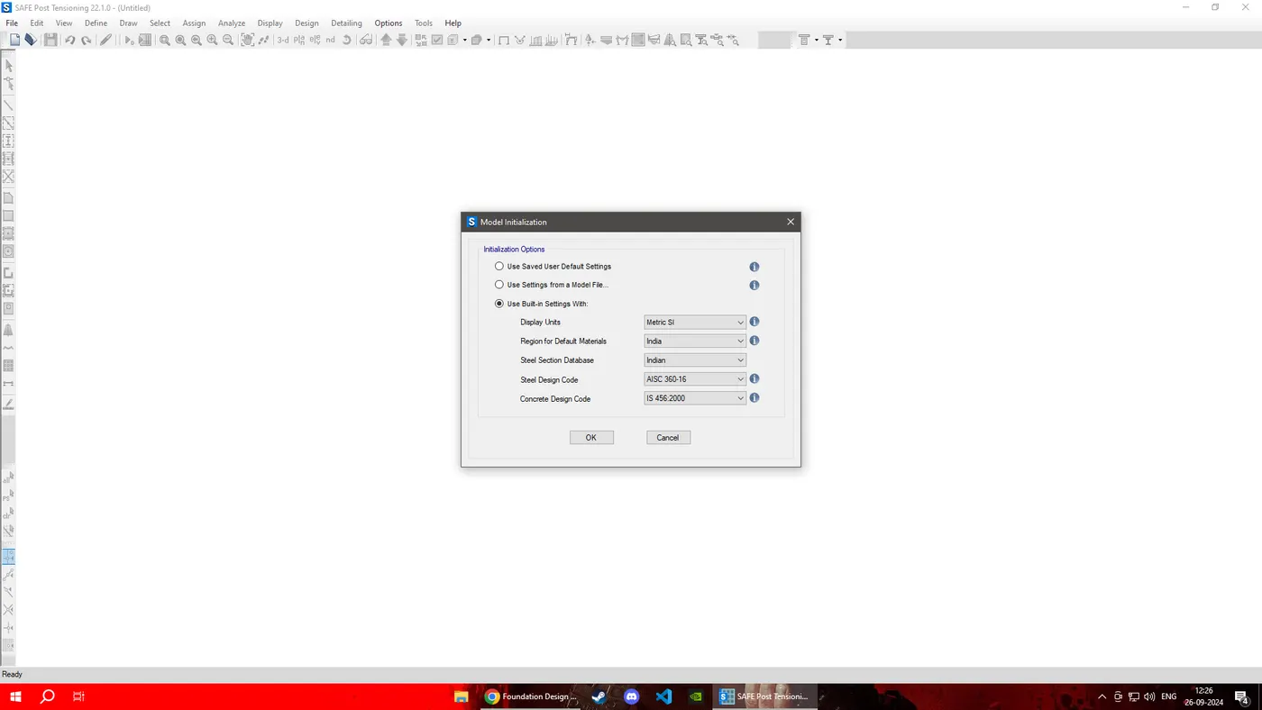
STEP: 1 Open the SAFE Application select New Model followed by Input Settings, Units was selected as Metric and Code IS 456-2000.
STEP: 2 Safe Bearing Capacity of Soil (SBC) = 150kN/M2
Un-factored Load = 2000/1.5 = 1333.33kN
1333.3/2 = 666.5kN
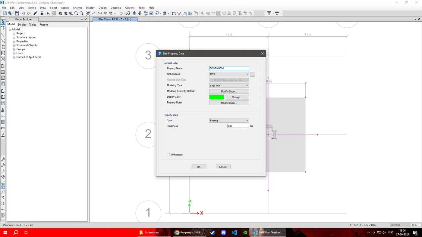
Depth of footing = 800mm
Subgrade Modulus = (F.O.S x SBC)/Settlement = (3 x 150)/0.05 = 9000kN/m3
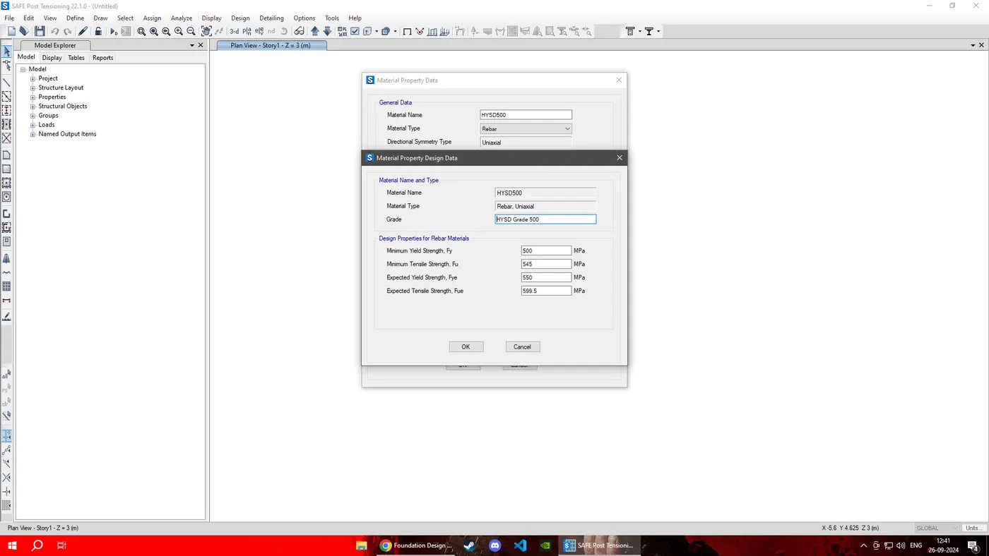
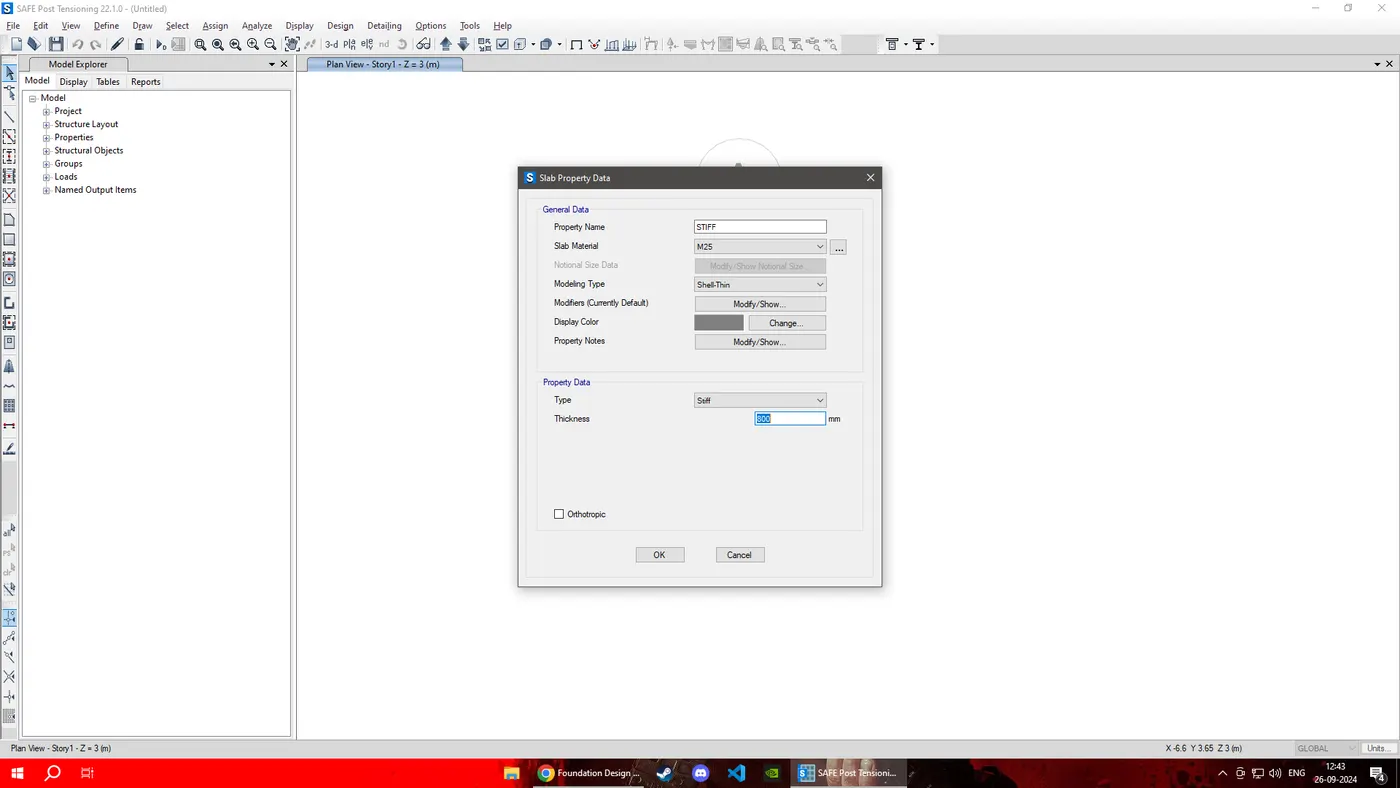
STEP: 3 Define materials and Slab Section Properties as Below:

STEP: 4 Define soil subgrade modulus
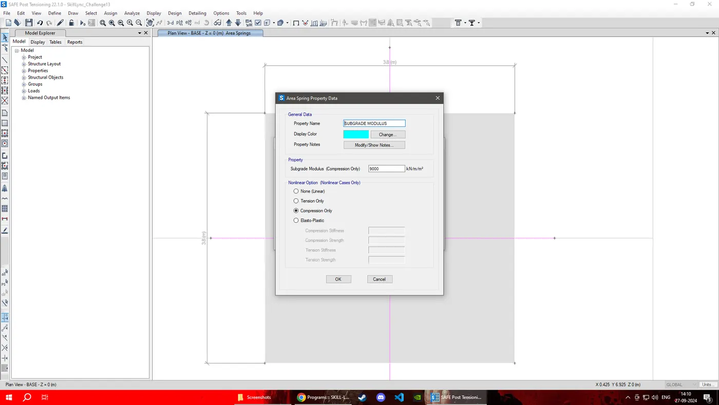
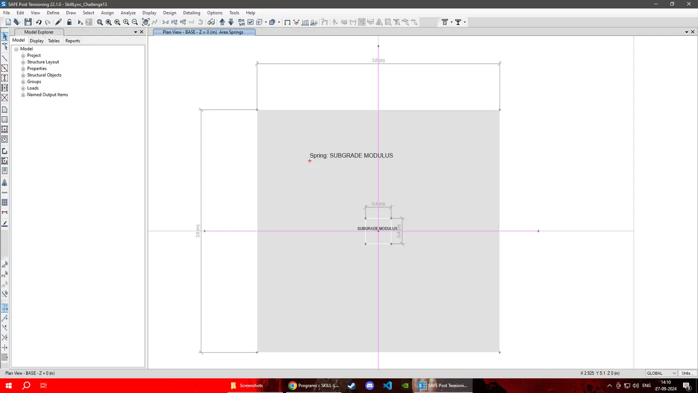
STEP: 5 Define Load pattern and Load Combinations
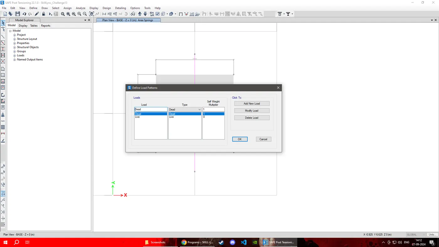
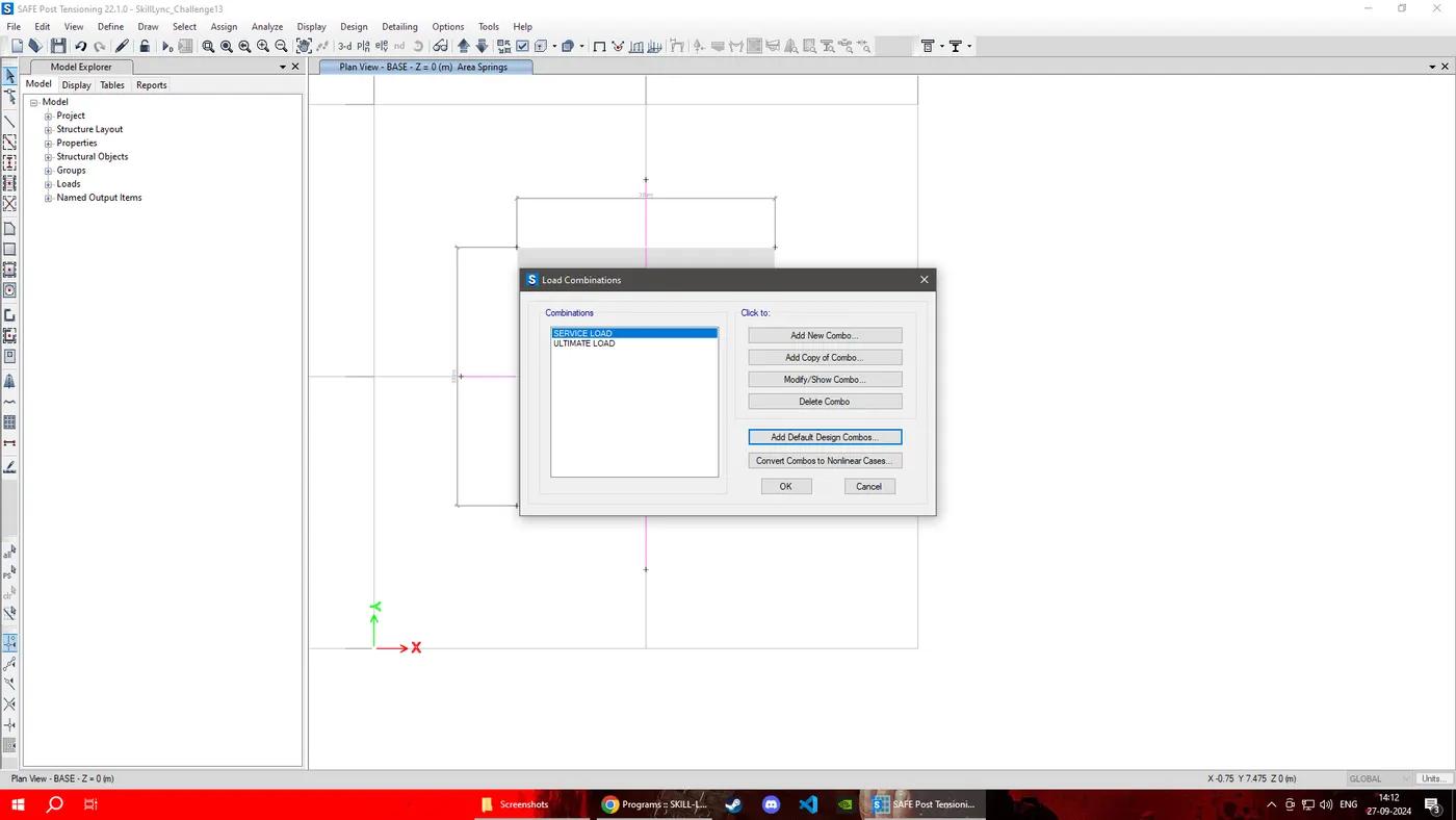
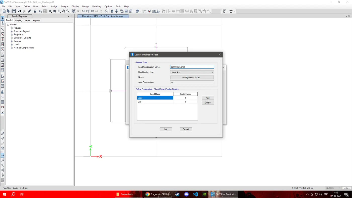
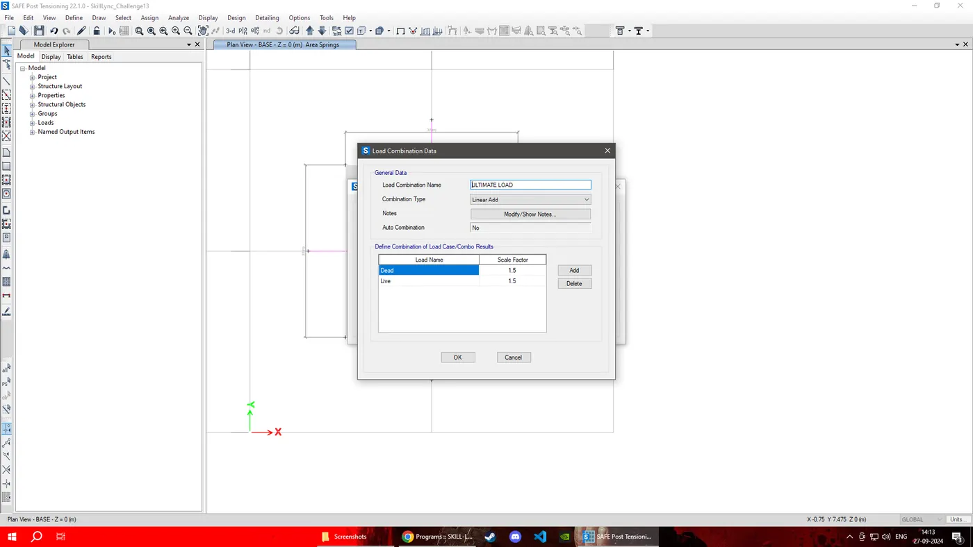
STEP: 6 Assign DEAD and LIVE load
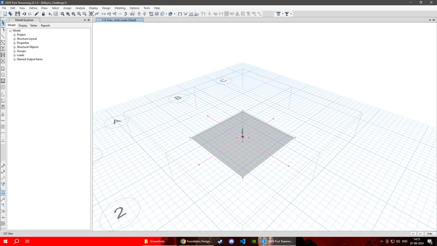
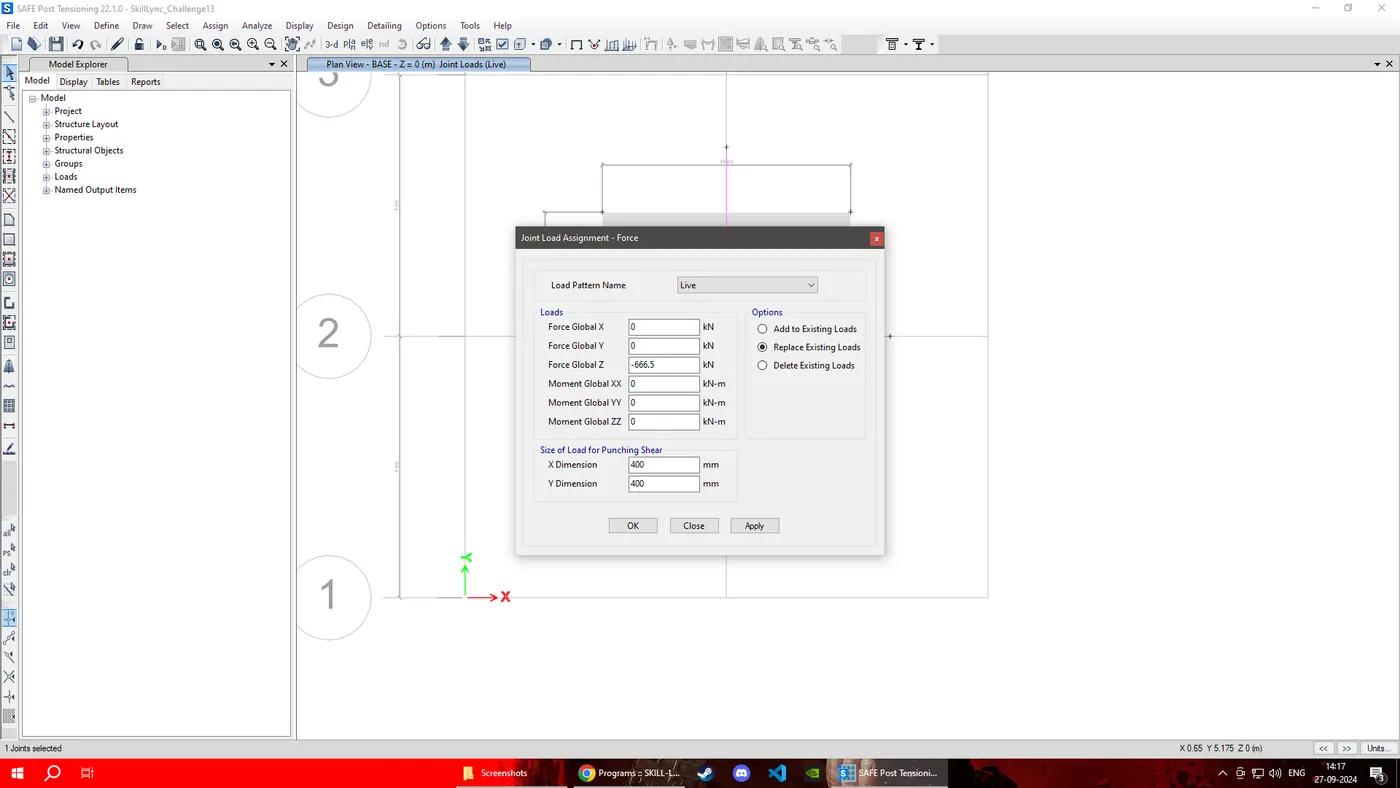

Provide 50mm as Top and Bottom Cover
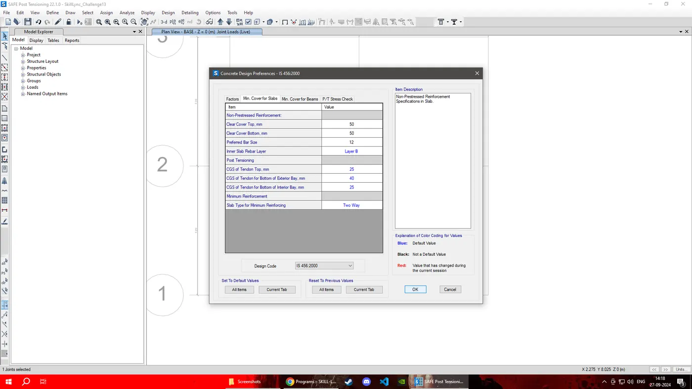
STEP: 7 Run analysis and design.
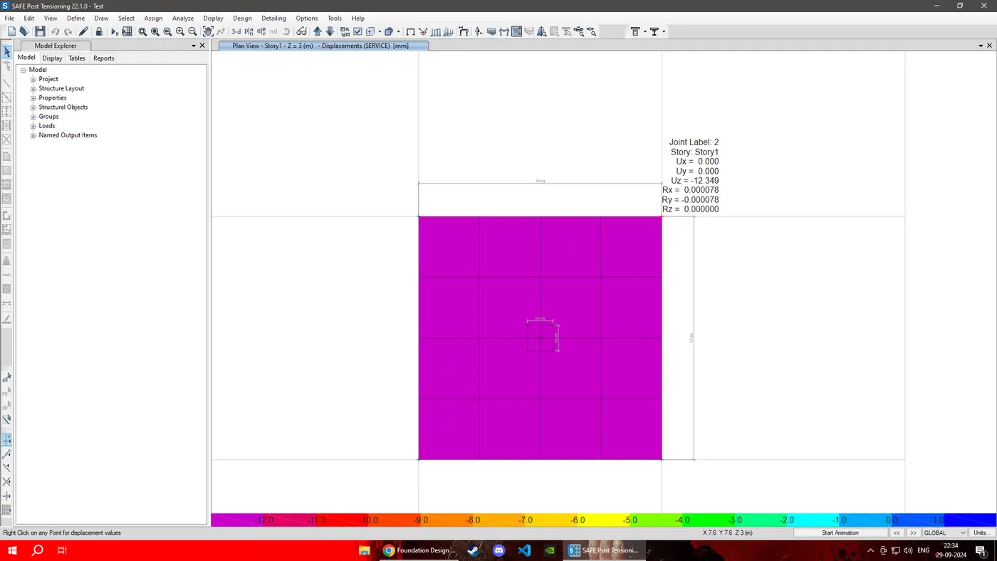
As Displacement is 12.34mm which is less than 50mm hence OK.
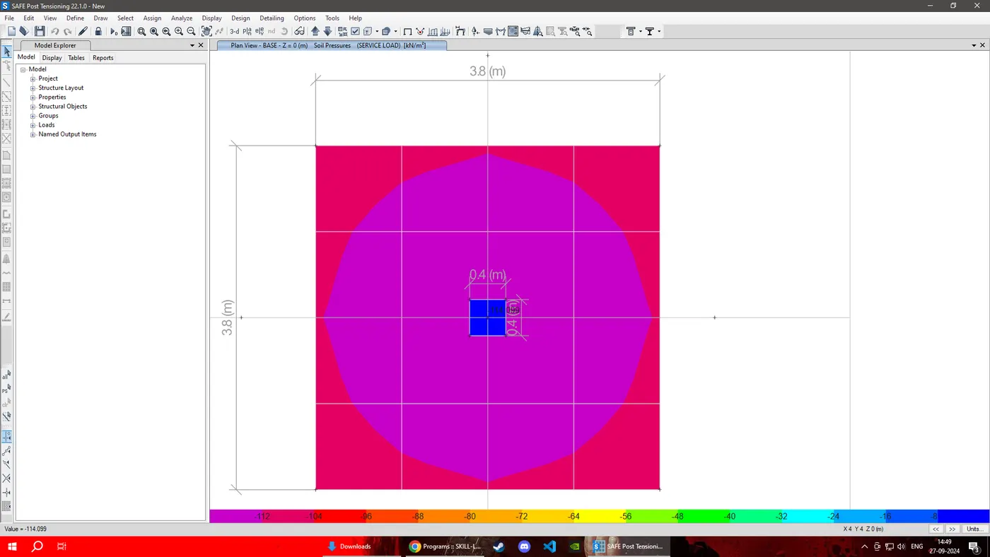
Soil Pressure is (114.099kn/mm2)also ok as it is under 150Kn/mm2
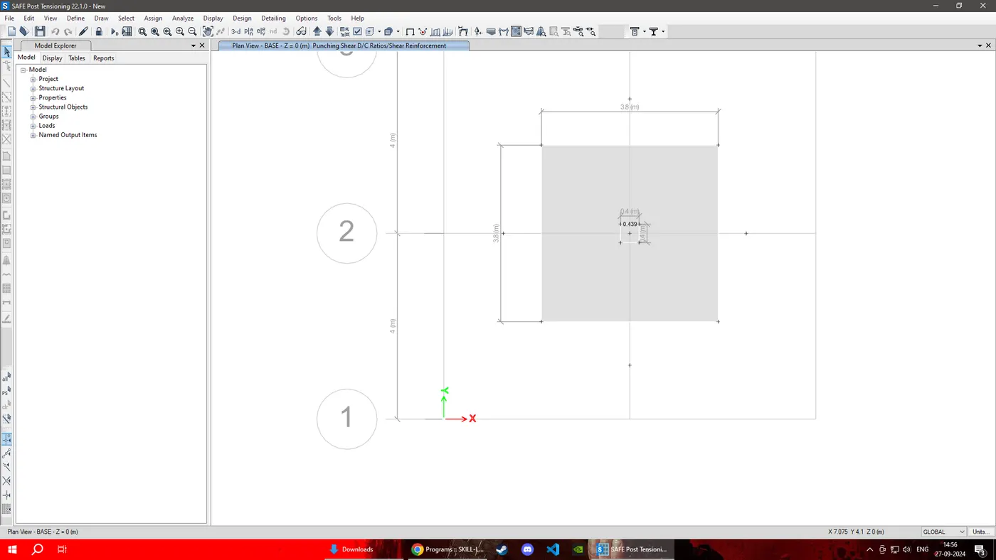
Punching Shear is 0.429 which is acceptable as it is less than 1.
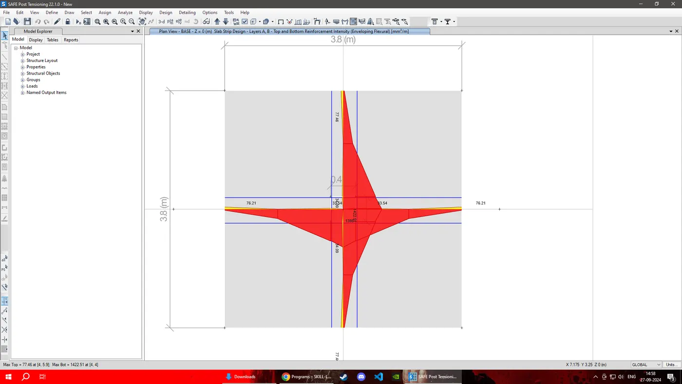
RESULT:THE ISOLATED FOOTING WAS DESIGNED AMD ANALYIZED IN SAFE SUCCESSFULLY.
2.) AIM: TO MODEL ANALYSE, AND DESIGN THE PILE CAP USING SAFE
PROCEDURE: Given Data :
Column Size = 600mm x 600mm
Un factored Load = 1175KN
Pile Length, L = 16m
Pile Diameter , d = 500mm
Load Carrying Capacity of 1 Pile = 200K
Calculations Required For Designing Pile:
Total Number of Piles Required = 1175/200 = 5.8 ~ 6
Area of Pile = (3.14/4)x5002 = 196349mm2
E = 25000 N/mm2
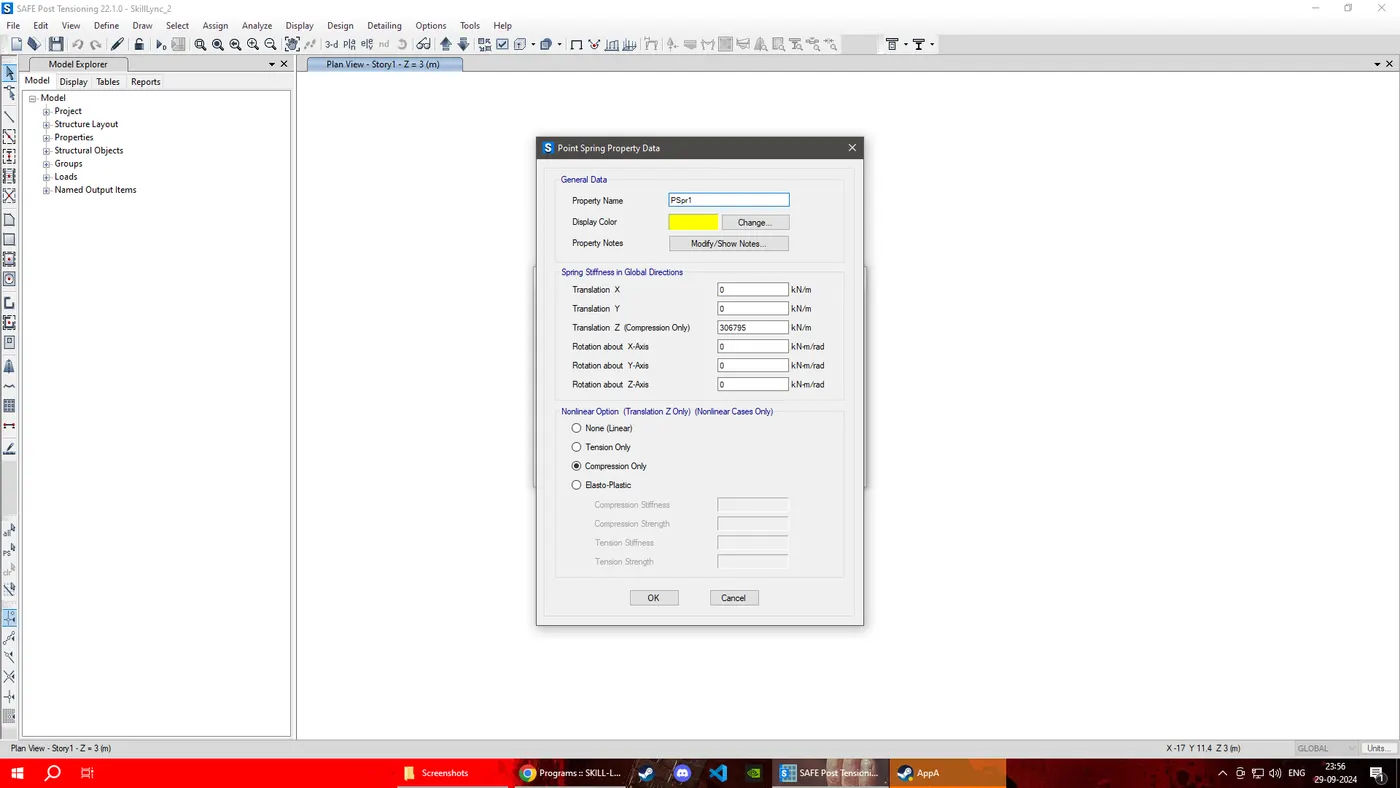
Spring Constant = EA/L = (25000 x 196349)/16000 = 306795 N/mm
Spacing from Edges of Cap = 250mm
STEP: 1
open CSI SAFE 22 add the below settings
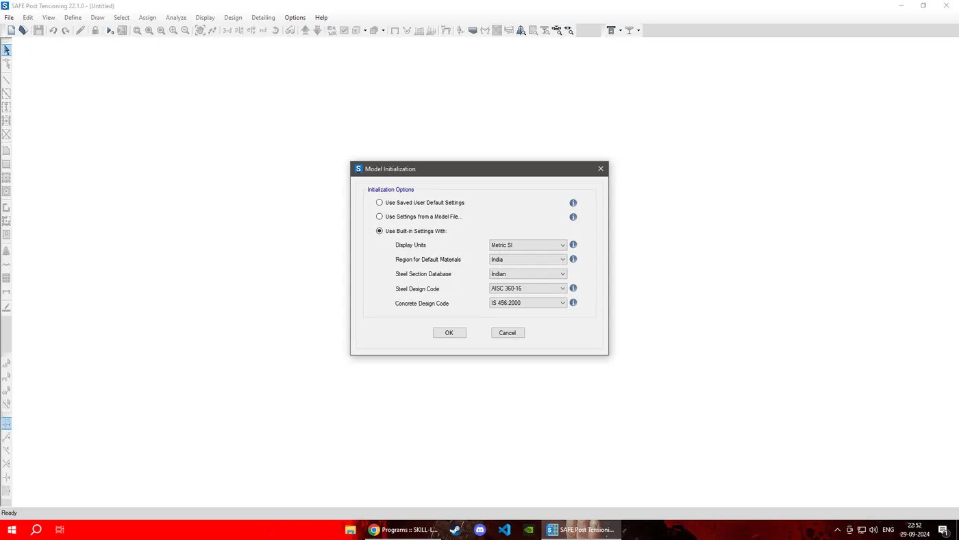
Material Property data:
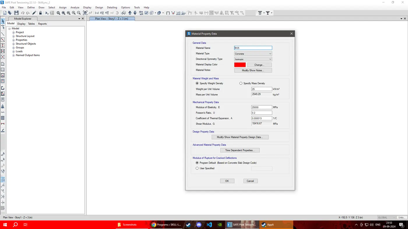
Click define followed by Material properties
M25 grade of concrete
Modulus of elasticity,
E = √25 X 5000 = 25000N/mm²
Fe 500 Rebar was added next as shown below
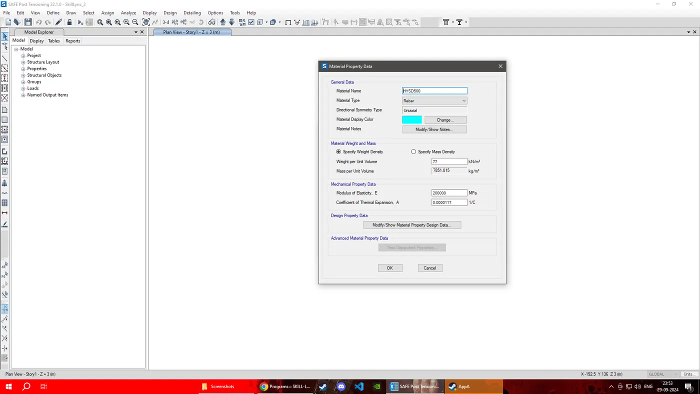
STEP: 2 Define slab properties as follows:
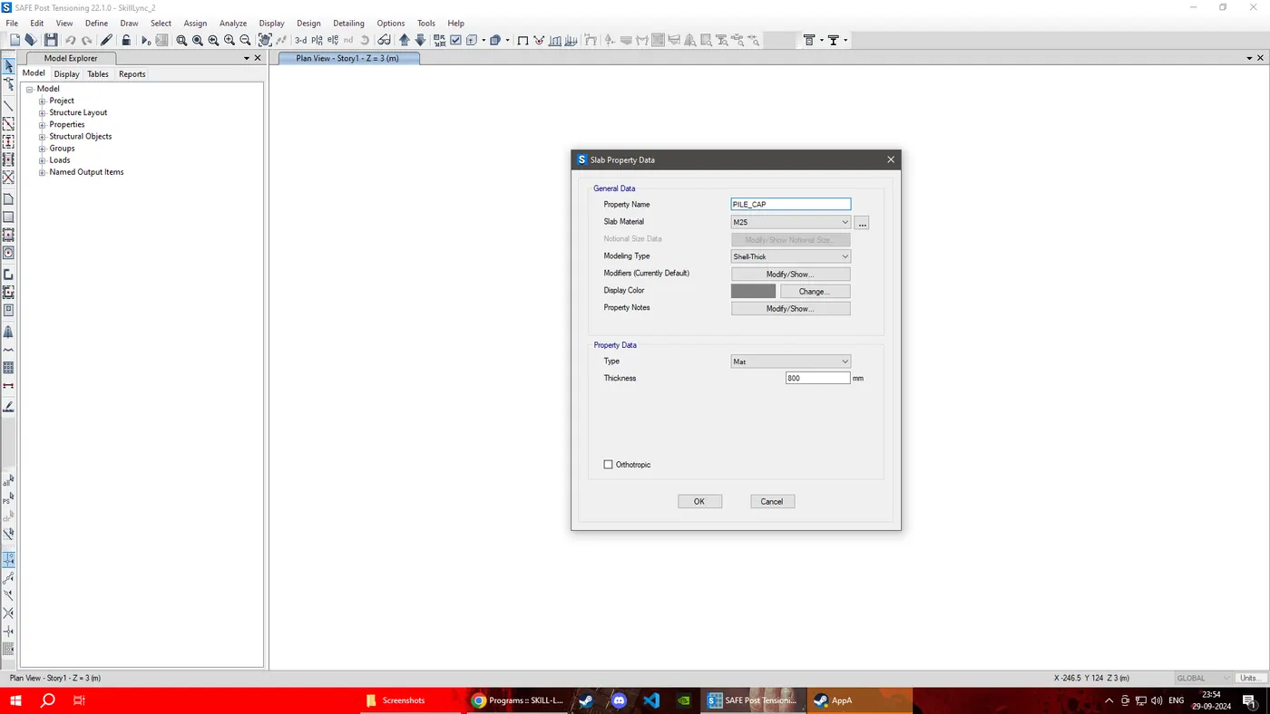
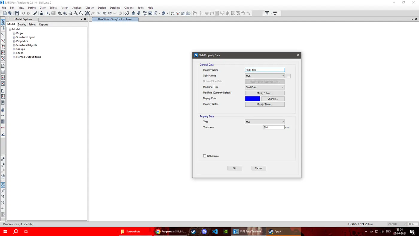
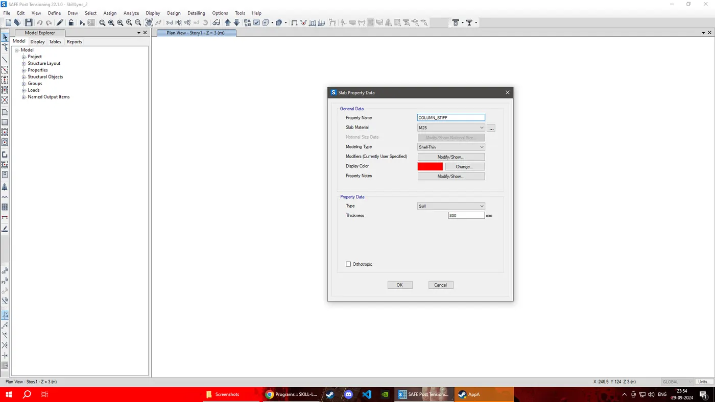
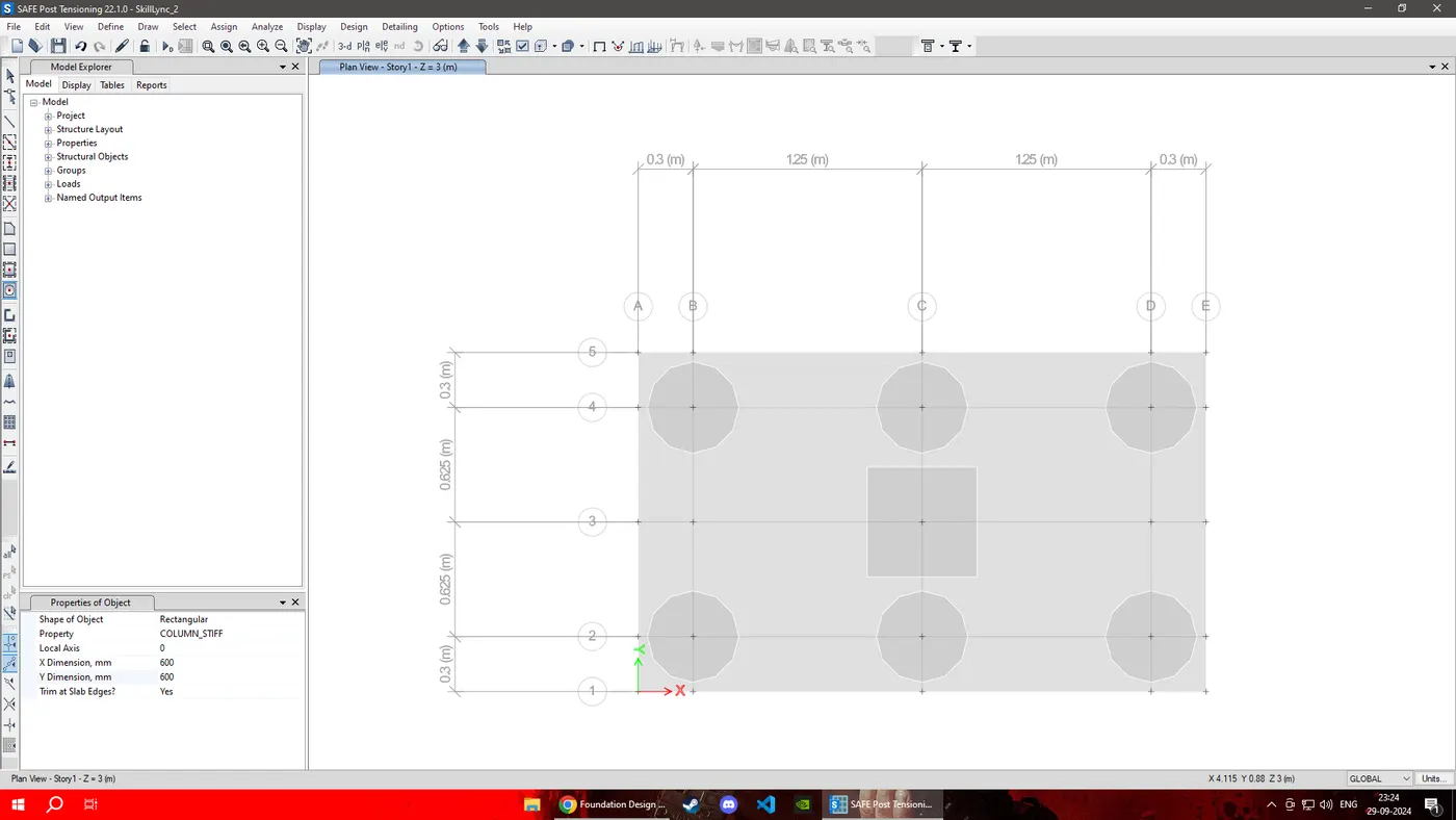
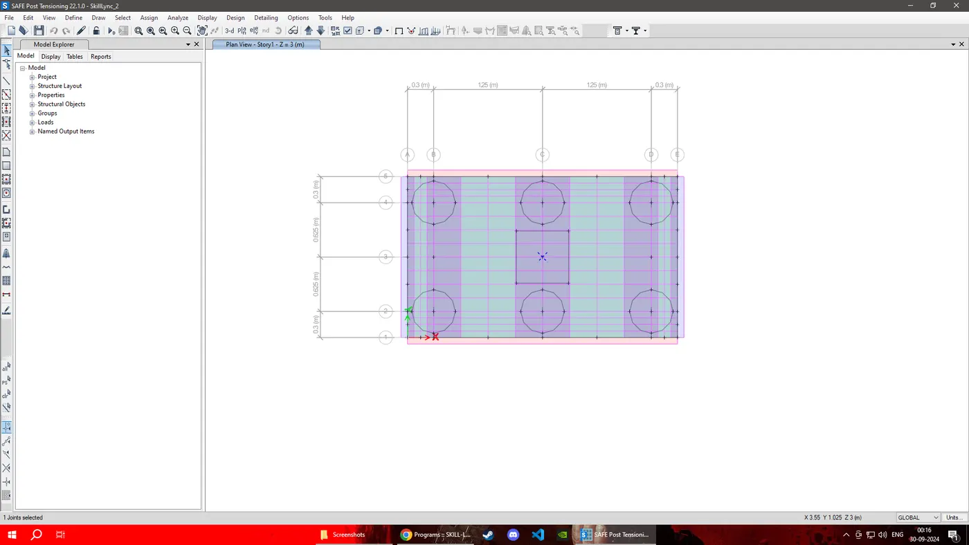
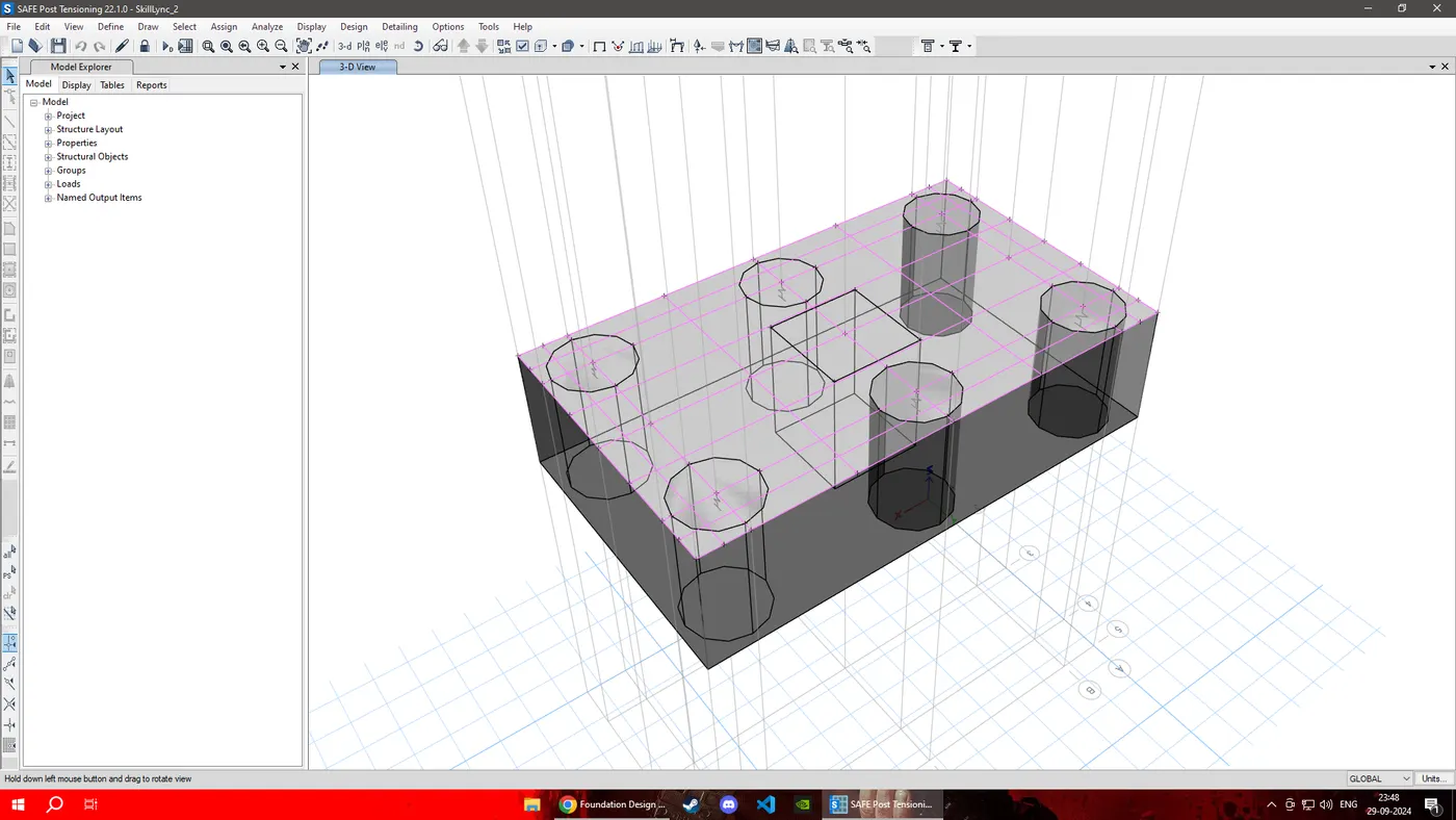
STEP: 3 Draw the slab by using quick draw tool and give the respective property
STEP: 4
Springs were added define->spring properties->point springs
check compression only and enter the value of spring constant we calculated above .
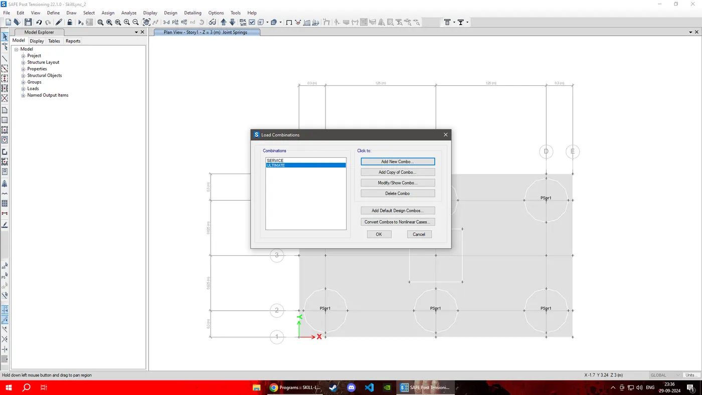
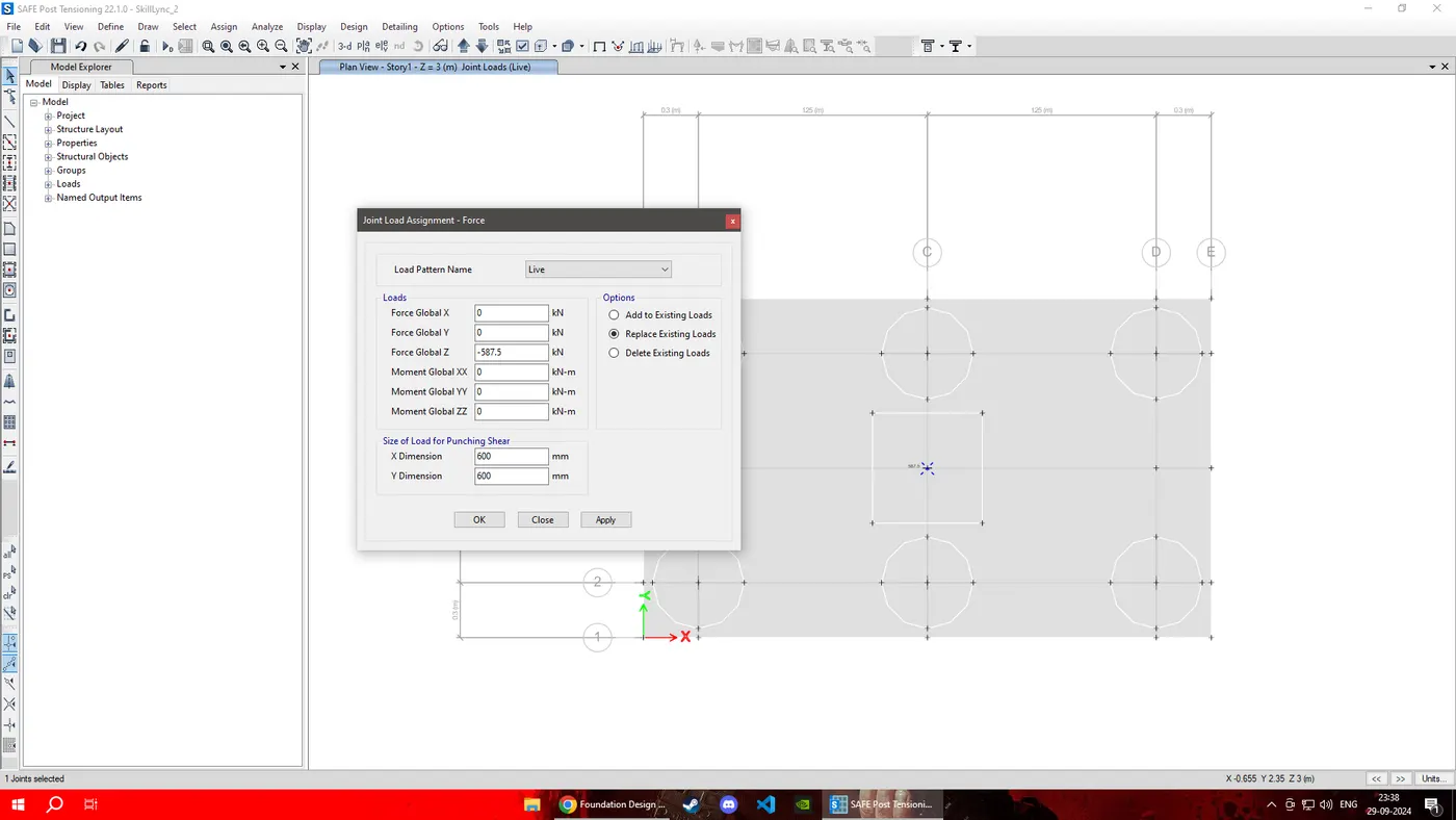
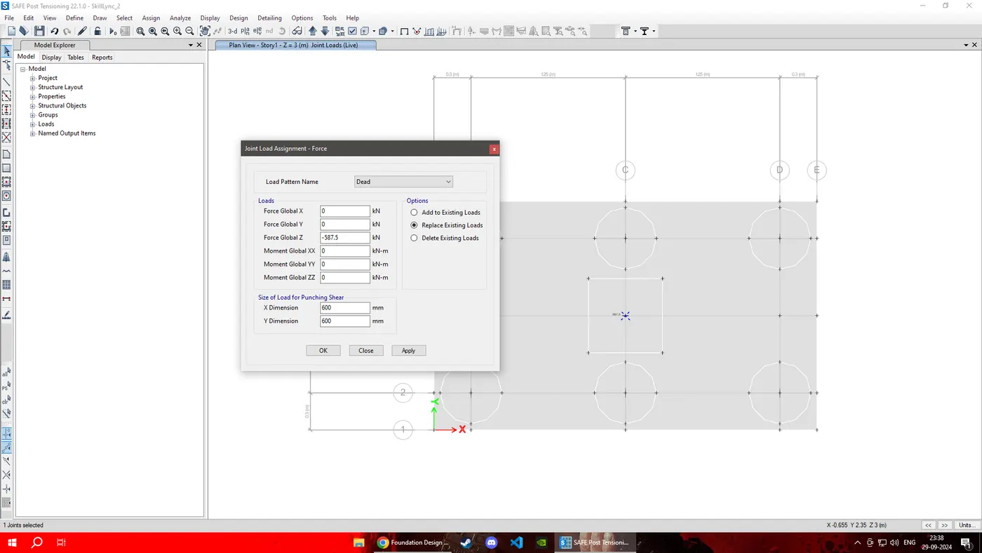
STEP: 5 Load case combination was defined next. and live load and dead load is added to column Stiff.
STEP: 6 Run the Analysis
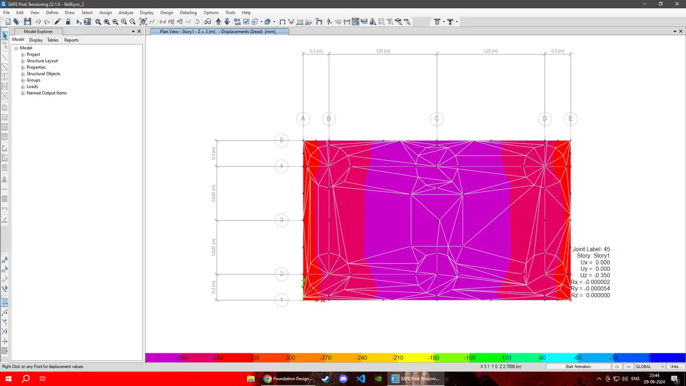
Displacement is under safe range .
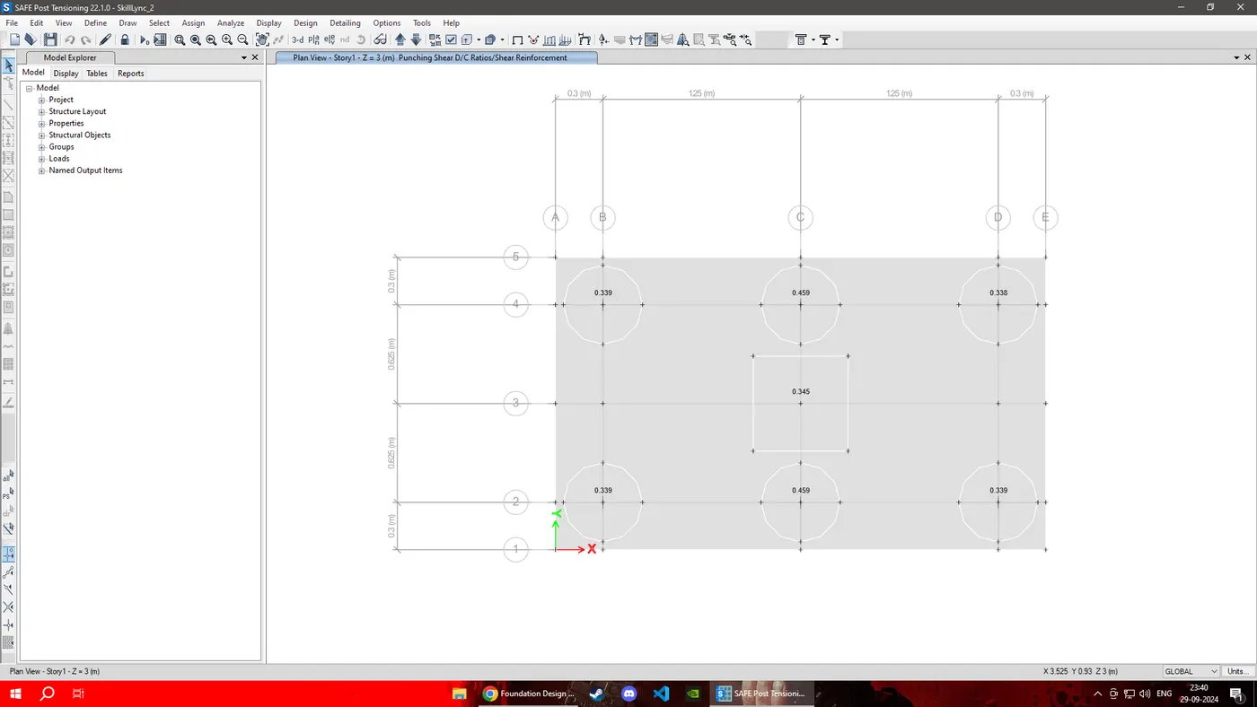
Punching Shear is all less than 1 and are at safe range.
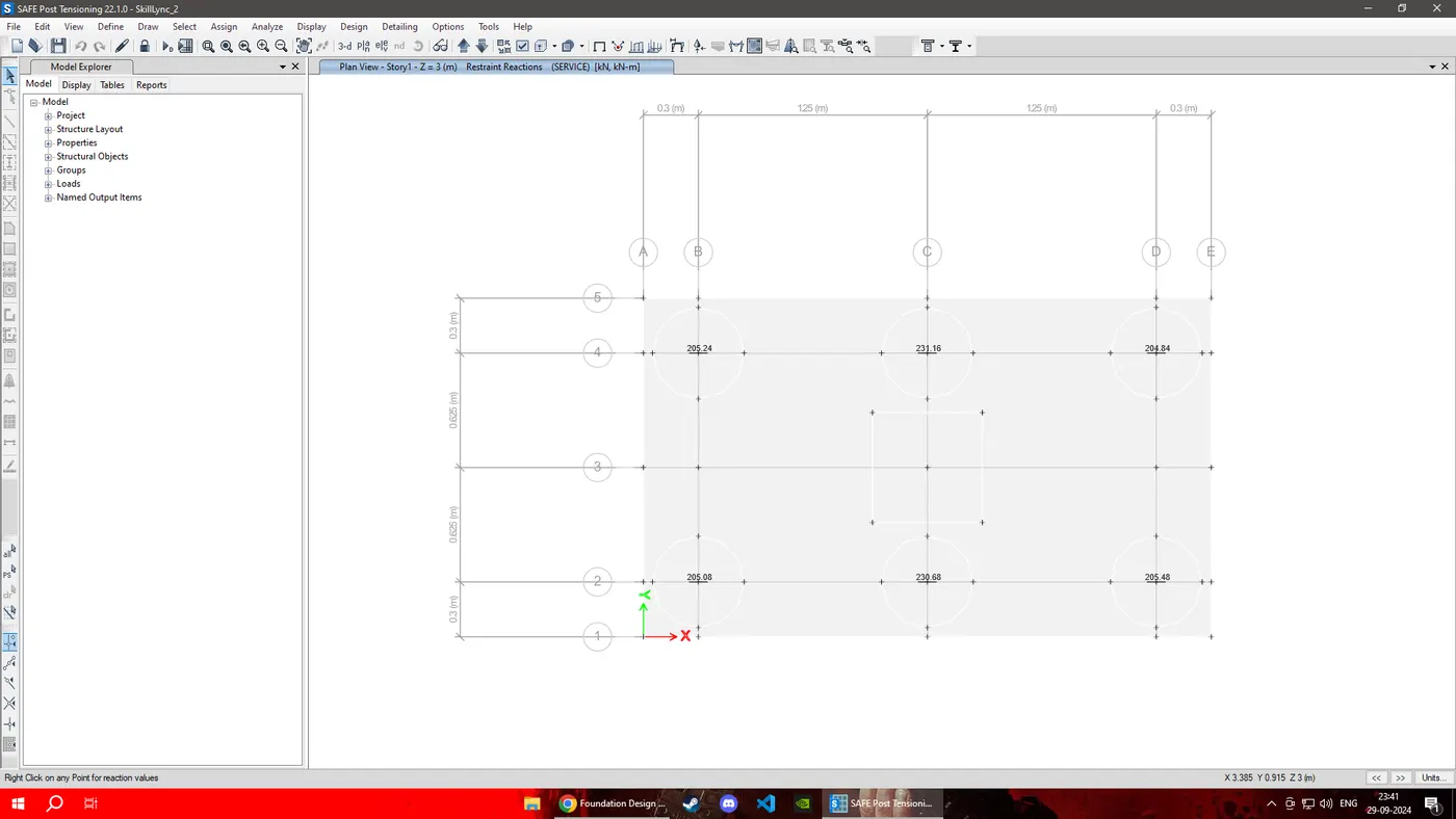
Reactions Forces are also in safe range.
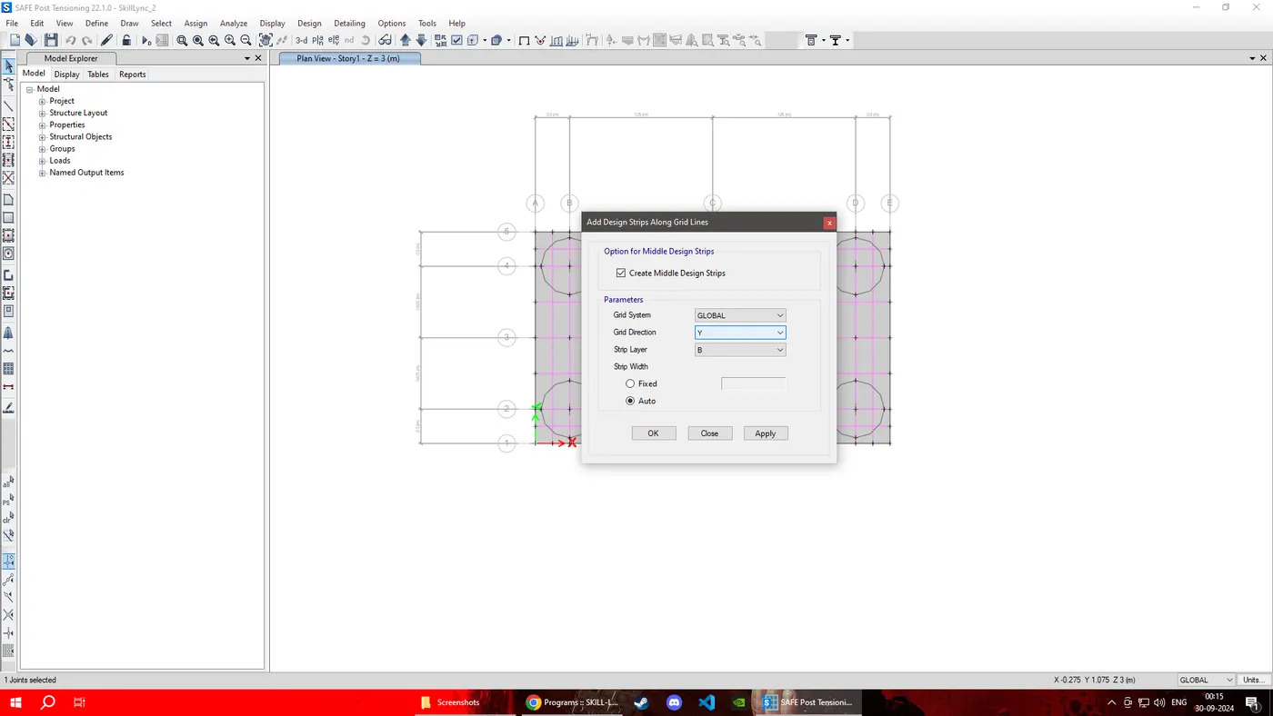
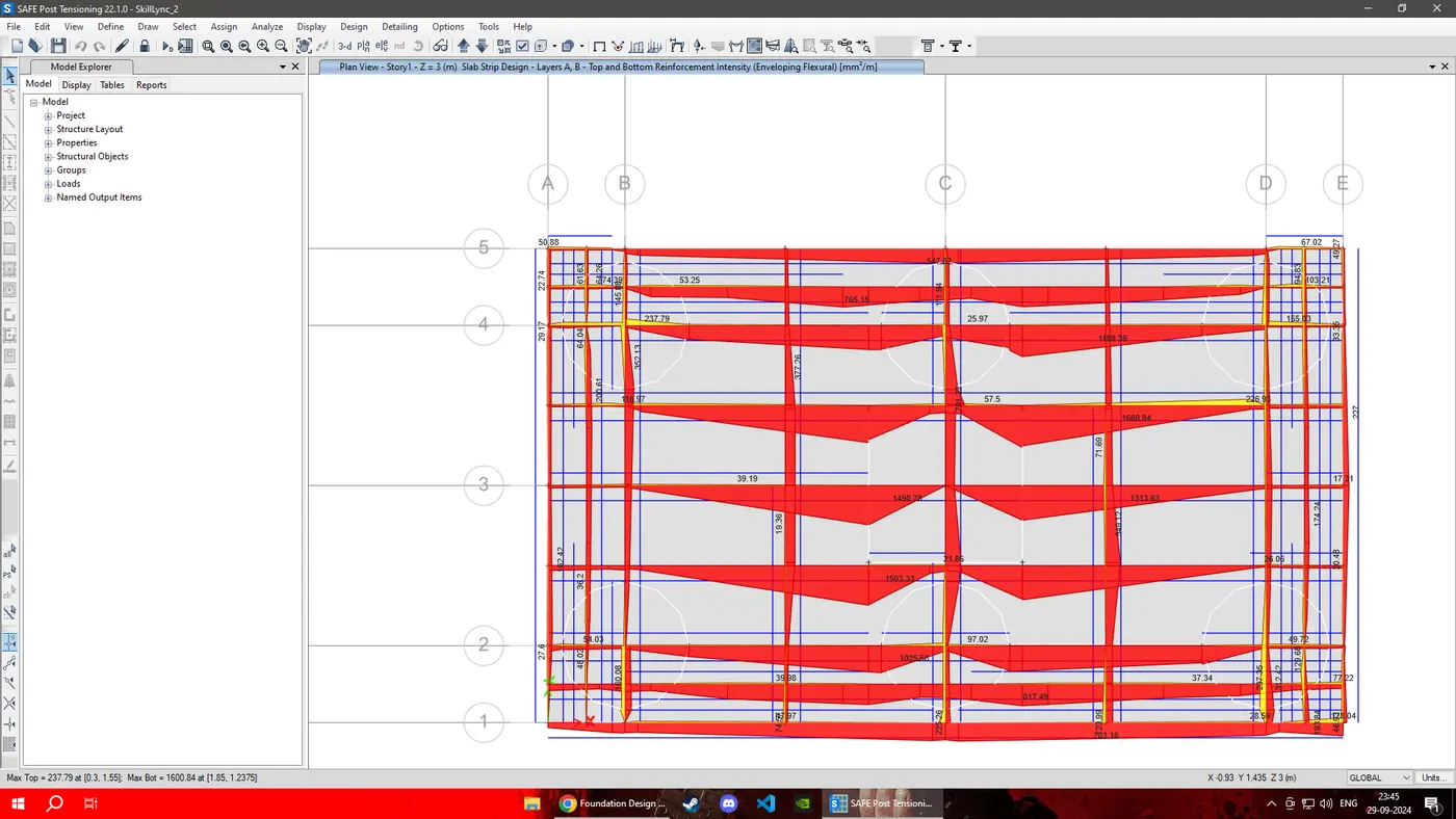
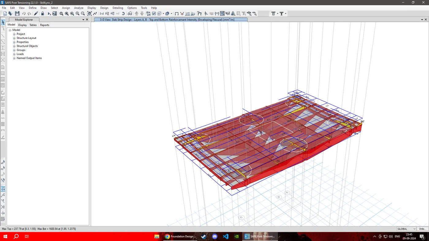
We unlock the model and add design strips along grid line and input above for both directions and layers.
RESULT: Complete design of pile cap foundation using SAFE software.