Foundation Design using SAFE
Foundation Design using SAFE
QUESTION:
1. Model the isolated footing provided in week 11 challenge on SAFE. Analyze and design it to verify the size, depth and steel provided as per calculations.
2. A column of size 600x600 carrying an unfactored gravity load (DL+LL) of 1175 KN is to be supported on pile cap, which ultimately transfers load to the piles underneath. Piles of 16 metres length and 500 mm diameter are to be used. Each pile has a load carrying capacity of 200 KN. Model, analyse and design the pile cap on SAFE to evaluate the following:
- Pile group to be used
- Depth of pile cap
- Longitudinal steel on top and bottom face in both directions
INTRODUCTION:
- SAFE offers a single user interface to perform modeling, analysis, design and reporting. A new model explorer is available for quick access to objects, properties and forms.
- SAFE is ideal for modeling foundations, basemats, and footings. Easily model soil supports and zero tension soil models with uplift analysis. The area assignment of soil supports is based on the subgrade modulus, and they automatically adjust whenever the mesh changes. Basemat foundation models can include pedestals, walls, columns, beams, and piles in addition to the foundation area.
- Design strips are used to define how reinforcement requirements are to be calculated. SAFE can automatically define the strips for you, or you can define them yourself.
- SAFE includes the ability to define post-tensioning in slabs, as banded or distributed tendons. An interactive tendon editor simplifies the task of laying out the tendon profiles. Tendon layouts can also be automated based on strip position and direction.
1-ANSWER:-
AIM: To Model the isolated footing provided in week 11 challenge on SAFE. Analyze and design it to verify the size, depth and steel provided as per calculations.
PROCEDURE FOR ISOLATED FOOTING:
- Design setup:
-Initially download the safe software and installed in your laptop / PC from the offical csi website.
-After installing the software the SAFE icon will appear on the desktop.
-Dobule click to run the software.and it will appear like the below image.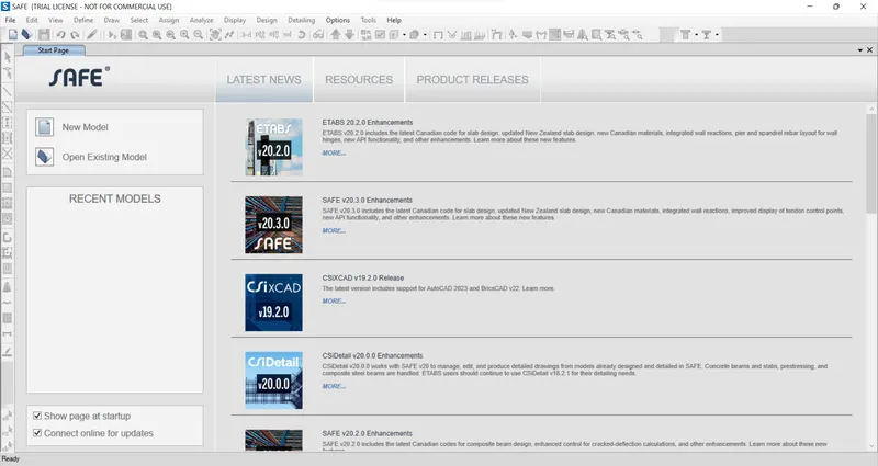
-then click on the new model.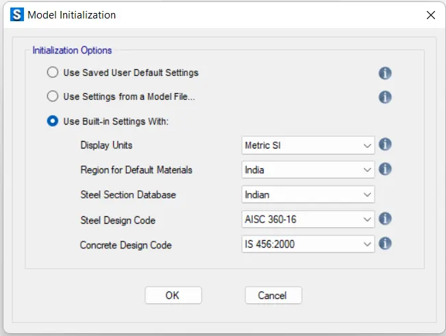
-then select the single footing template.and click on OK.then it will appera the single footing template.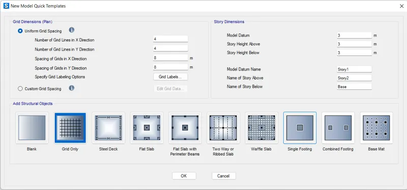
-after appearing the single footing template. enter the all details in the tempalate accoring to the details given in the question.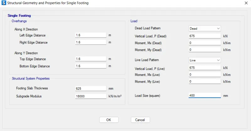
-then it will show footing with column with grids.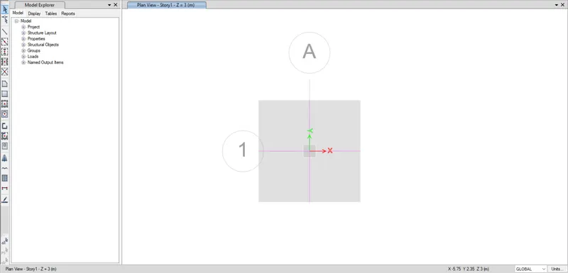
- Defining the properties for materials:-
-It is simple to define the materails smae as like ETABS software.
-lets go to the define tab- materail property thenclick it.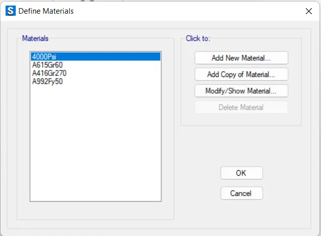
-then click on the add new property then add the comcrete grade as M25.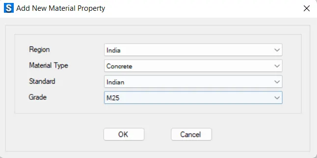
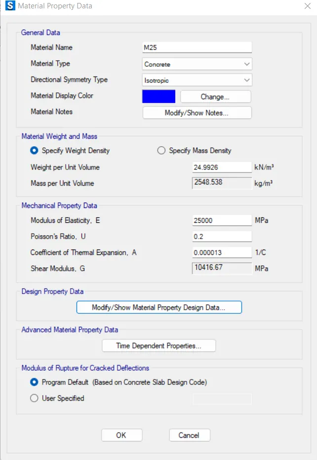
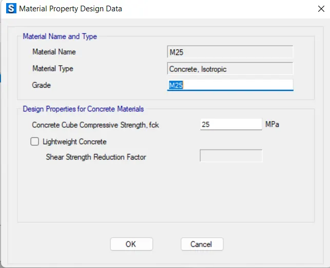
-Then add the material of steel grade as FE-500.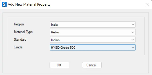
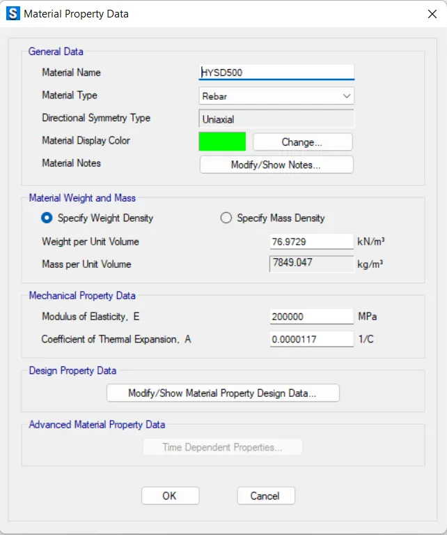
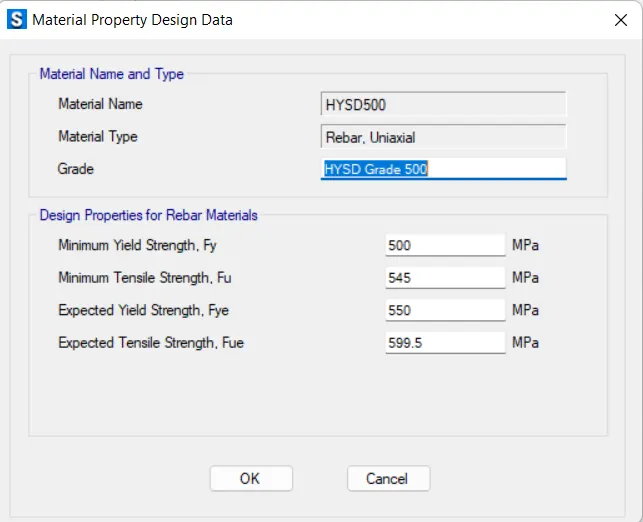
-Then show the list of the materials.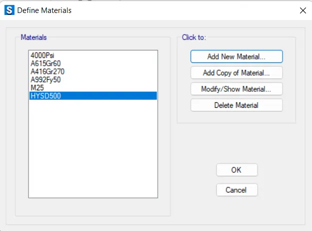
- Defining the properties of the section:
-To define the section properties - go to the define tab- section properties-slab sections.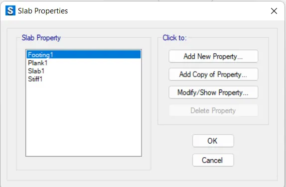
-then the add the new two section proprties. One for Footing and another for the column(stiff sllab).
-Slab for footing.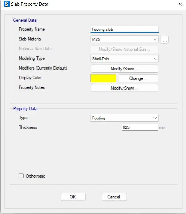
-stiff for the column: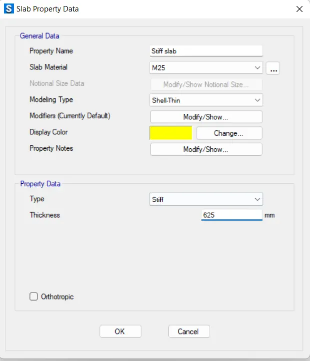
- Difining the load combination;
-At the starting of the template we are added the load cases. so we are now definig the load combinations for that.
-however there are the two tytpes of load combinations we should add. they are service loads (SLS)and ultimate load combinations(ULS).
-For the ULS we should 1.5 factor is multiplied by the load cases.
-Fisrtly go to the definr tab-load combinations- add new combo.
-For SLS load Combo: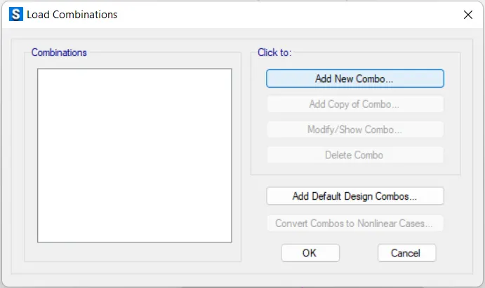
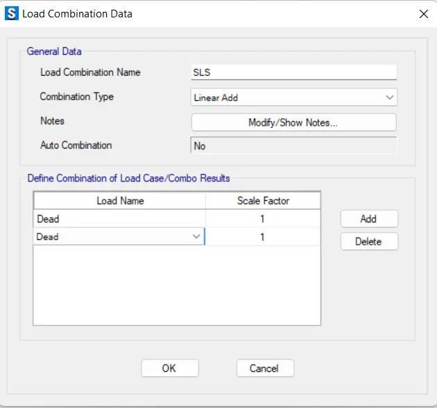
-FOR ULS load Combo: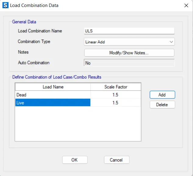
-the list of the load cominations are shown below.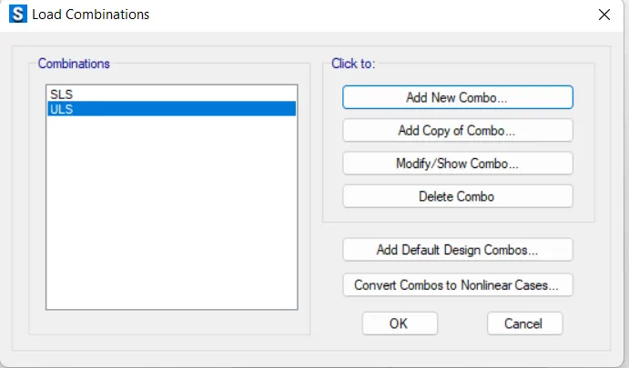
- Now assing the load cases:
-we already assign the loads while in the startin of the template.
-now once check the load either appiled or not.
-then go to the display- show loads assigned- dead / live load - ok.
-dead load.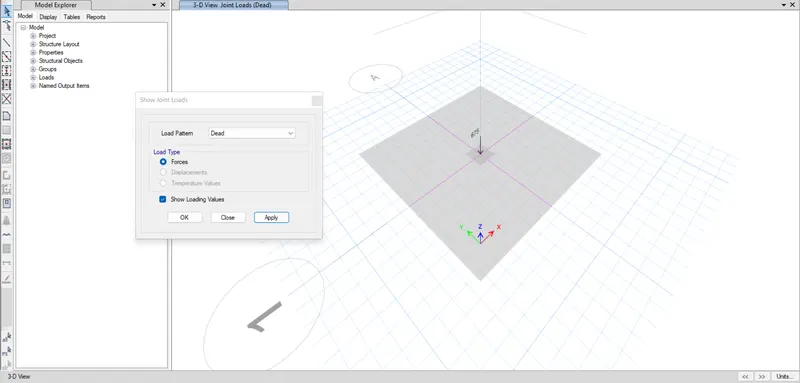
-Live load: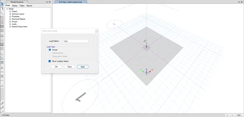
- Now defining and assigning the soil spring:
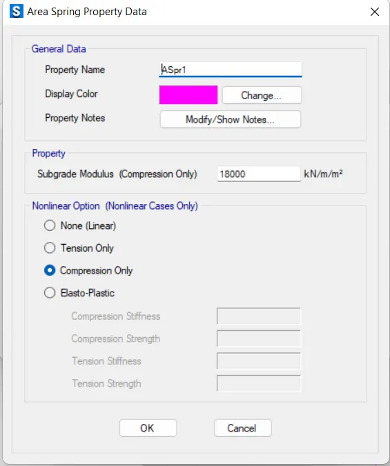
-the spring constant of the soil is = Factor of safety(FOS)*Safe bearing capacity(SBC)/ allowable settlement.
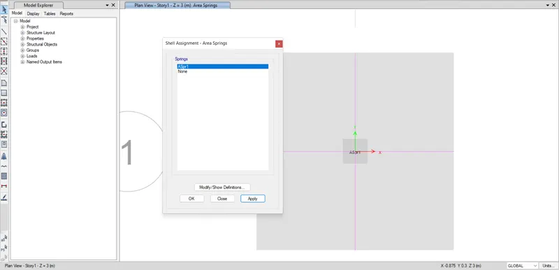
-Then select the footing - go to assign -area spring spring 1 ok.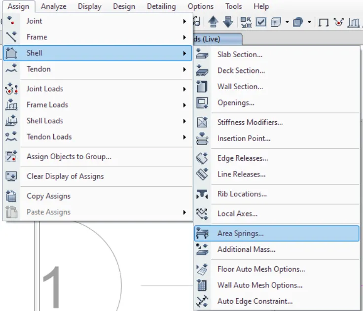
- Run the analysis and design:
-after the assign tha loads and all check the model is ok. after that run the analysis .it similar to the ETABS software.
-after doning the run analysis now we have to some checks if the design is fooring is safe or not.
- Settlement check:
-firstly we need to observe the settlement of footing slab in mm.
-then go to display-show deformed shape-sls load combo ok.
-For isolated column it should not exceed 25mm of maximum displacement as per the code.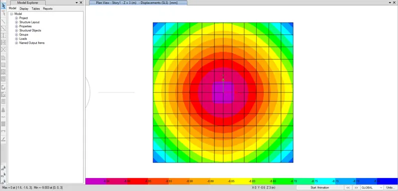
now we obatin the maximum setllemnt as 8mm which is less so it doesnot exceeds the 25mm.
hence the settlement in this not exceed the maximum value . henece ok.
- Soil pressire check:
-now see if the soil pressure due to the SLS is within the range of SBC as per the question.
-Now go to the -display-soil presuure-SLS load Combo-ok.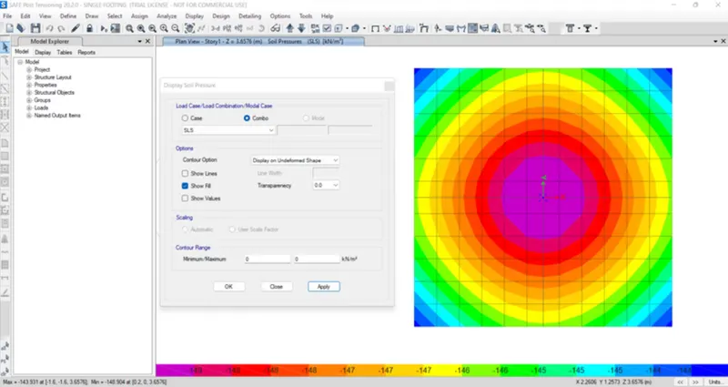
In our case its shows the `149 (kn)/(sq.m)<150(kn)/(sq.m)`.
-hence is it is also safe.
- Punching shear check.
-sam eas the before. Go to the display-punching shear-uls load combinations-ok.
-we check by the demand/ capacity ratio must be less than 1 at each joint.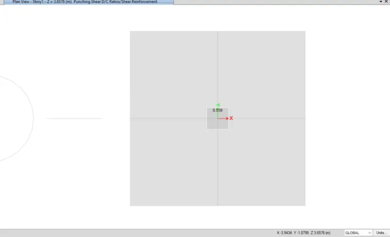
-in our case 0.6<1 hence safe.
- Rienforcement requirement:
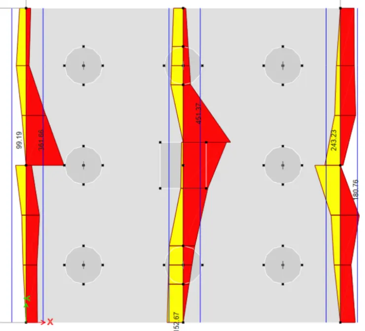
-now we need to add the design strips .
-Go to add desig strips- add in x and y direction respectively, with the two layers of A and B respectively.
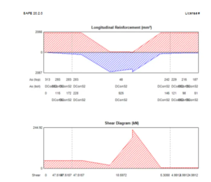
-After that go to display-show slab desgign ok.
FOR STRIP A: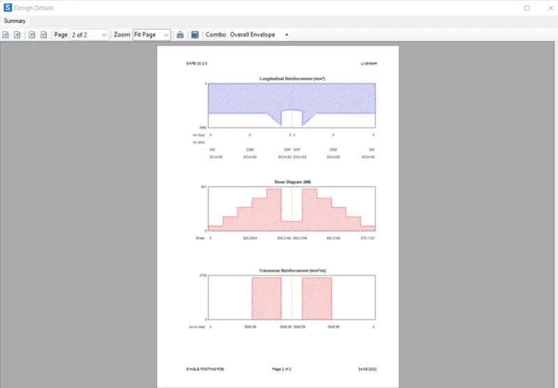
FOR STRIP B: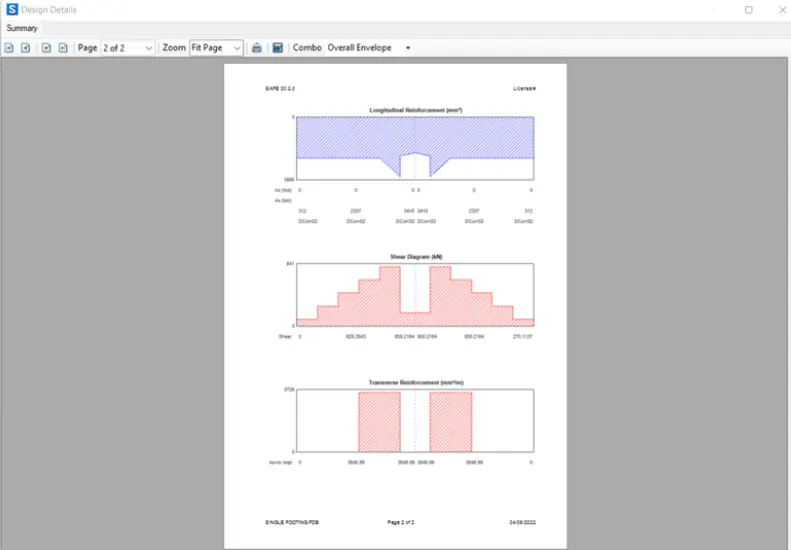
2-ANSWER:
AIM:
To design a column of size 600x600 carrying an unfactored gravity load (DL+LL) of 1175 KN is to be supported on pile cap, which ultimately transfers load to the piles underneath. Piles of 16 metres length and 500 mm diameter are to be used. Each pile has a load carrying capacity of 200 KN. Model, analyse and design the pile cap on SAFE to evaluate the following:
- Pile group to be used
- Depth of pile cap
- Longitudinal steel on top and bottom face in both directions
PROCEDURE:
- Given data:
-SIze of the column:`600mmxx600mm`
-unfactored gravity load: `1175kn`
-Lenth of the pile: `16m`
-Dia of each pile:`500mm`
-Bearing capacity of ech pile:`200kn`
--caluclating the number of piles= Total load/ bearing capacity of each pile =`(1175xx1.1)/200=6.46~~8nos`
where 1.1=soil surchage pressure.
--Spring constant =`(AE)/L=306796.15n/(mm)`
--Length of the pile= c/c distance between the two piles= 2.5x pile dia
=`2.5xx500=1250mm`
the n we adopted for `1300mm`for the purpose of the safe design.
--Distance from the edge of the footing to the egde of the pile: `1xx`pile dia
=`1xx500=500mm`
-- As per the above calculations we adopted the size of the footing has `4.1mxx4.1m`. - Design setup:
-Initially download the safe software and installed in your laptop / PC from the offical csi website.
-After installing the software the SAFE icon will appear on the desktop.
-Dobule click to run the software.and it will appear like the below image.
-then click on the new model.
-Then select the grid only option.and enter the details of the grid as we caluclated before.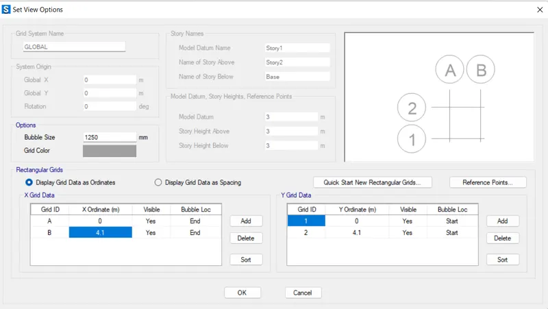
-Then it appear like this in the safe software.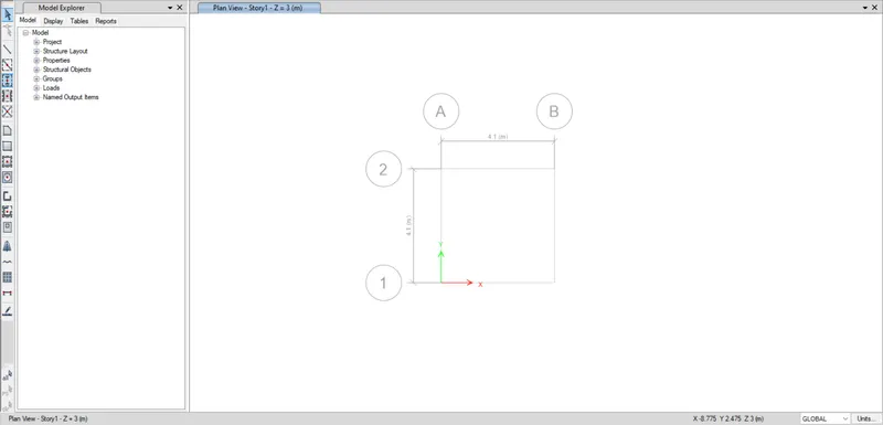
- Defining the material property:
-It is simple to define the materails smae as like ETABS software.
-lets go to the define tab- materail property thenclick it.
-then click on the add new property then add the comcrete grade as M25.
-Then add the material of steel grade as FE-500.
-Then show the list of the materials.
- Defining the properties of the section:
-To define the section properties - go to the define tab- section properties-slab sections.
-we need to draw the dummy points inorder to draw the all piles and columns.
-FOR PILE CAP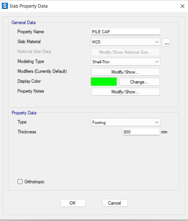
-FOR COLUMN STIFF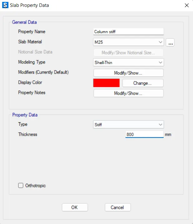
-CIRCULAR PILES: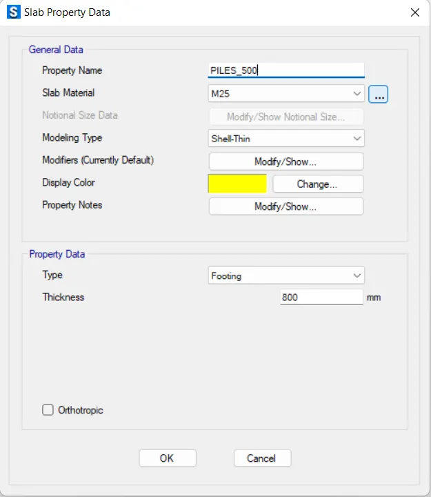
- Draw the pile sections :
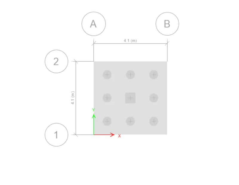
-now, initially draw the enire pile foundation .
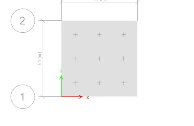
-in order to draw the stiif column and circular piles we need to draw some refrence points.
-Go to draw refernece points- specify the offsets- and locate the points.
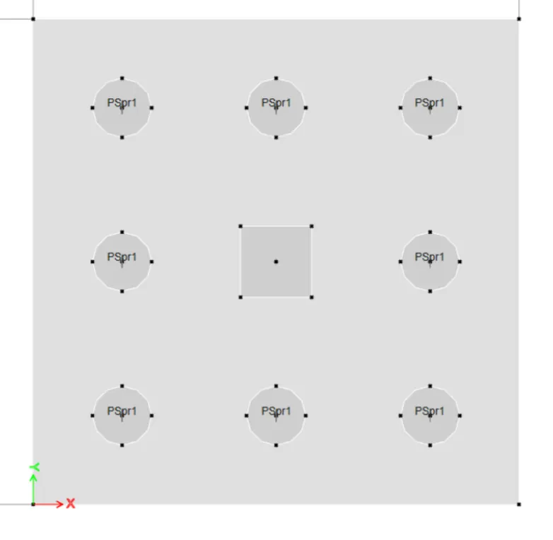
-Then draw the piles and column stiff.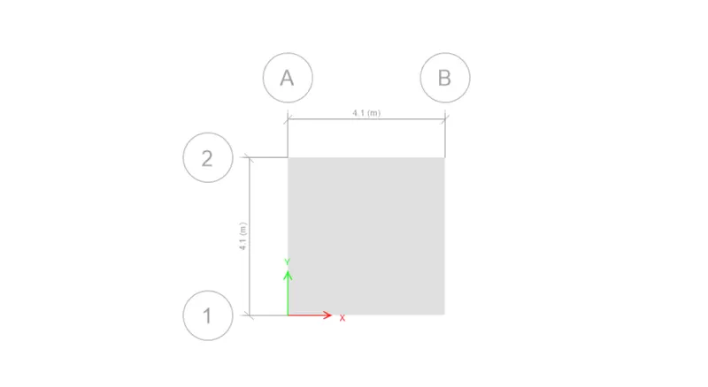
- Defining and assigning the point spring:
-Already we have caluclate the spring constant at the before.
-Go to define spring -point spring -add new- enter the spring constant value-check comprression only-ok.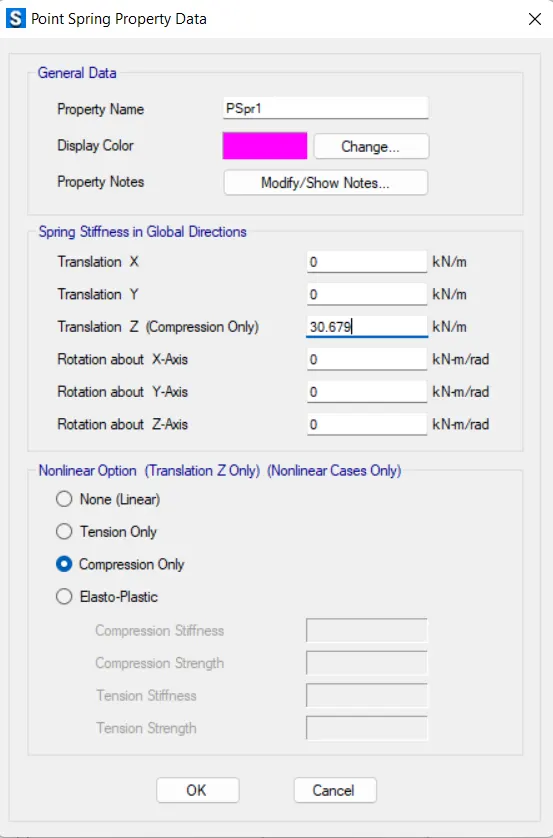
- Assigning the loads:
-Dead load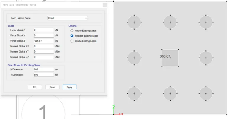
-Live load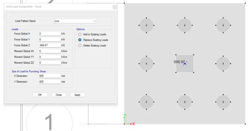
- Difining the load combination;
-At the starting of the template we are added the load cases. so we are now definig the load combinations for that.
-however there are the two tytpes of load combinations we should add. they are service loads (SLS)and ultimate load combinations(ULS).
-For the ULS we should 1.5 factor is multiplied by the load cases.
-Fisrtly go to the definr tab-load combinations- add new combo.
-For SLS load Combo:
-FOR ULS load Combo:
-the list of the load cominations are shown below.
- Run the analysis and design:
-after the assign tha loads and all check the model is ok. after that run the analysis .it similar to the ETABS software.
-after doning the run analysis now we have to some checks if the design is fooring is safe or not.
- Settlement check:
-firstly we need to observe the settlement of footing slab in mm.
-then go to display-show deformed shape-sls load combo ok.
-For isolated column it should not exceed 25mm of maximum displacement as per the code.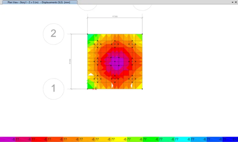
now we obatin the maximum setllemnt as `7mm` which is less so it doesnot exceeds the 25mm.
hence the settlement in this not exceed the maximum value . henece ok.
- check for punching shear:
-same as the before. Go to the display-punching shear-uls load combinations-ok.
-we check by the demand/ capacity ratio must be less than 1 at each joint.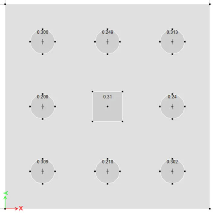
-in our case 0.313<1 hence safe.
- Base reactions @ PILES:
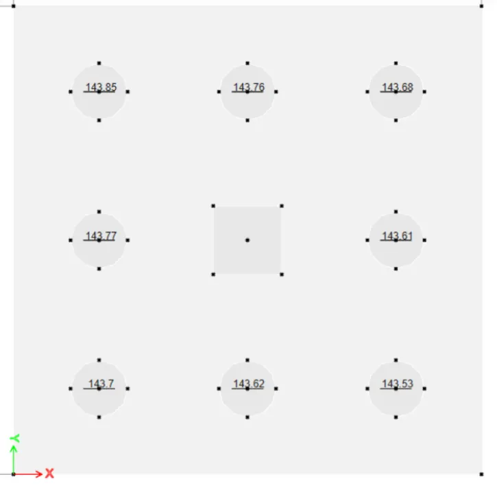
-in our case bearing capacity is `143.85<200kn`. Hence OK.
- Rienforcement requirement:
-now we need to add the design strips .
-Go to add desig strips- add in x and y direction respectively, with the two layers of A and B respectively.
-After that go to display-show slab desgign ok.
FOR STRIP A: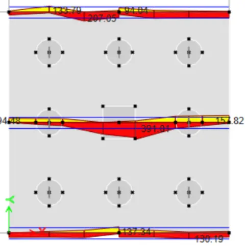
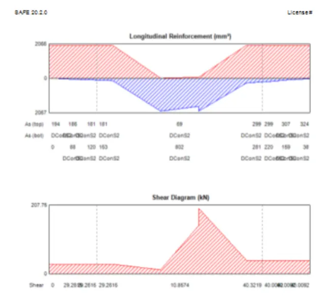
FOR STRIP B: