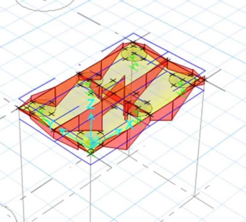
Foundation Design using SAFE
AIM : to find the analysis of isolated footing on SAFE and to verify its size and depth.
INTRODUCTION ; This isolated footing is done using safe software.
PROCEDURE:
STEP 1:
Open the SAFE software

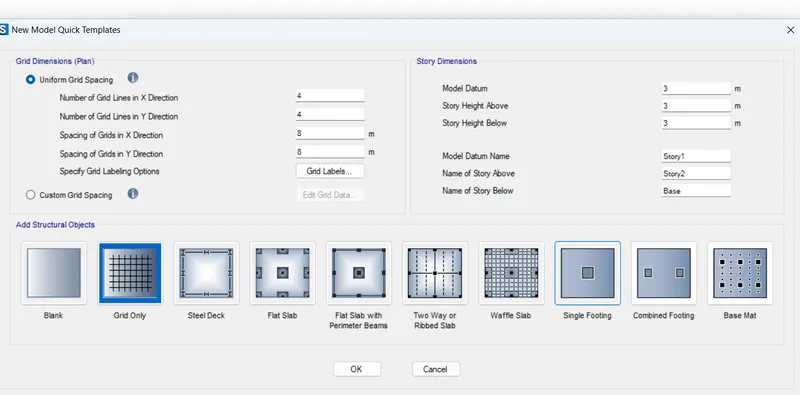
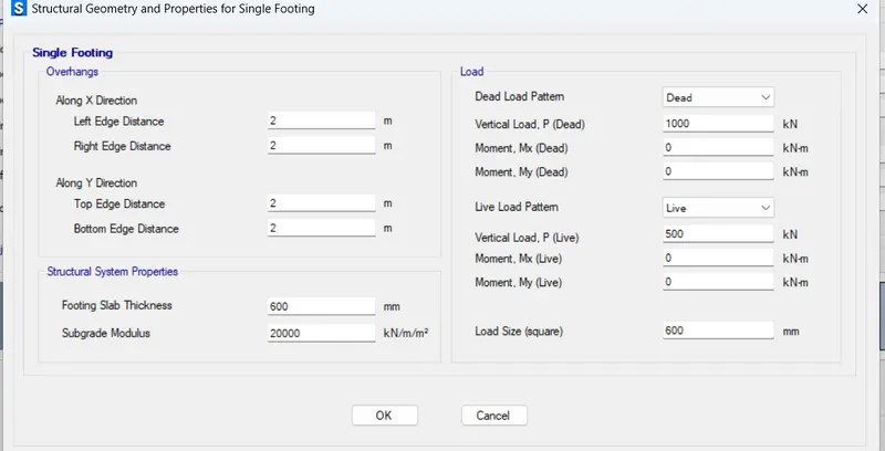
Select a new model
select the unit code in metric code and code IS 456-2000
STEP 2:
Define materials
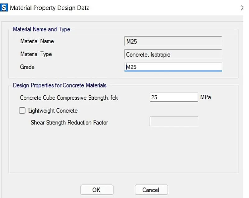
Add M25 concrete
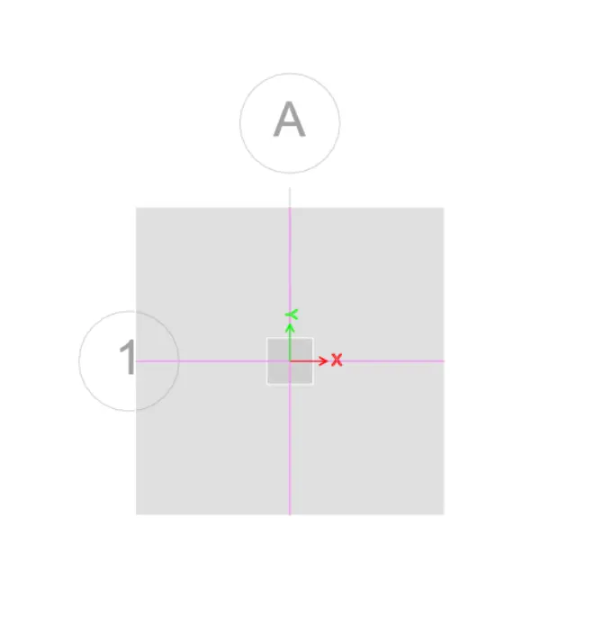
Material properties are shown below
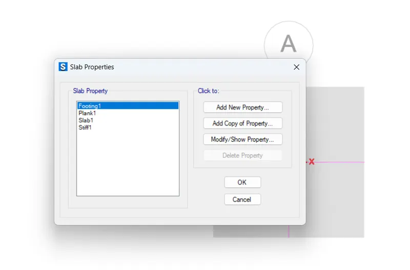
Add rebar Fe500
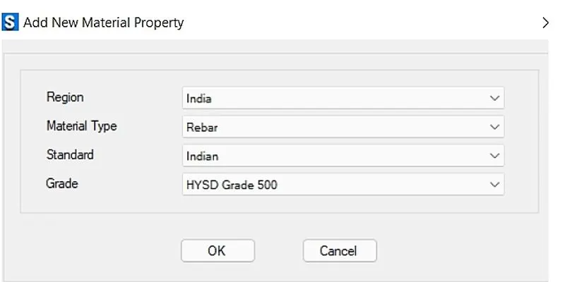
Material property data is shown below:
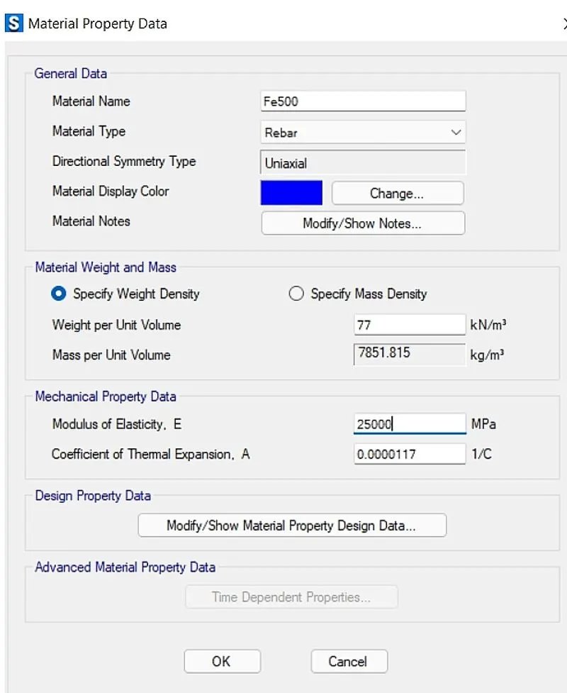
Material property data:
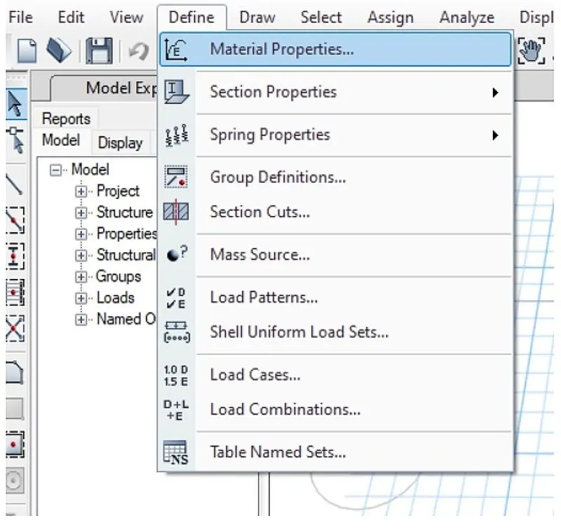
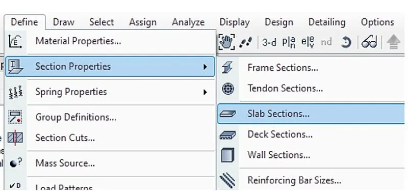
Click define followed by material properties
M25 grade of concrete
Modulus of elasticity,
E=root25 x 5000
=25000N/mm^2
STEP 3:
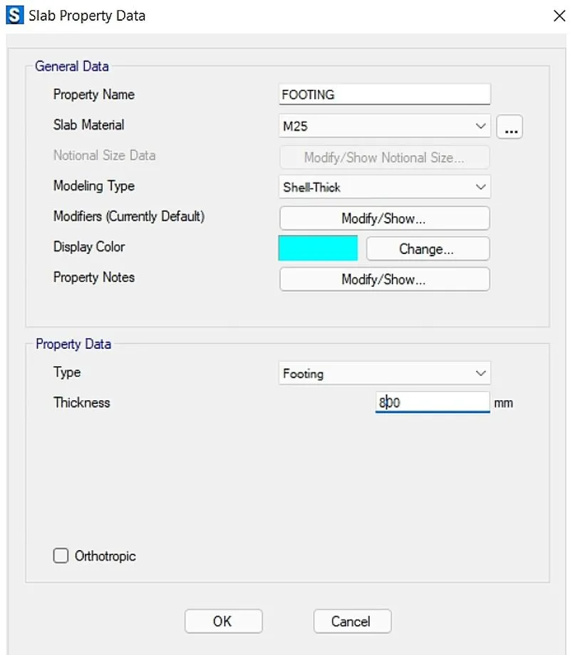
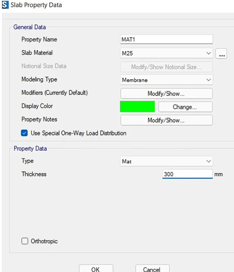
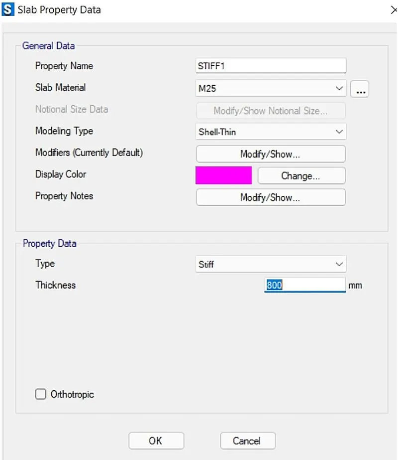
Define slab properties
Define properties for footing
Define properties for mat
Define properties for stiff which is under the column
STEP 4:
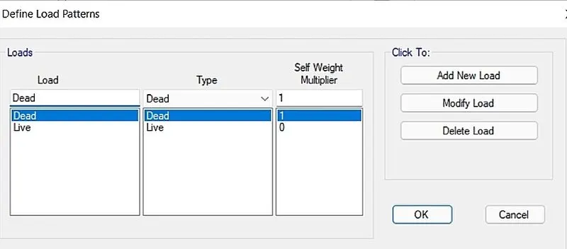
Define load pattern
STEP 5:
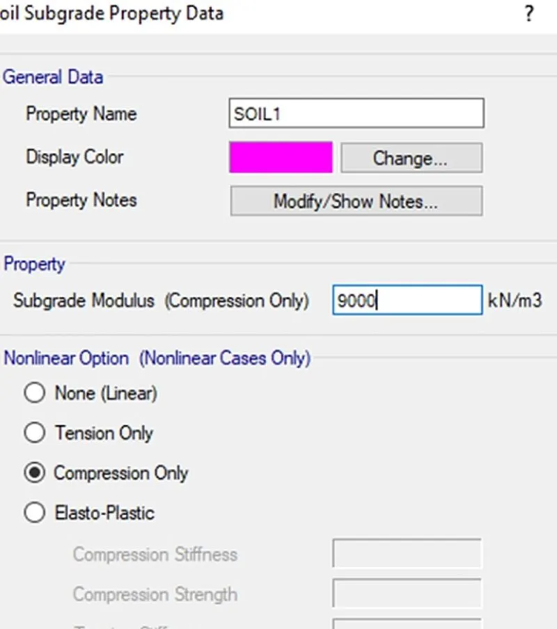
Define soil subgrade properties
column properties is shown below
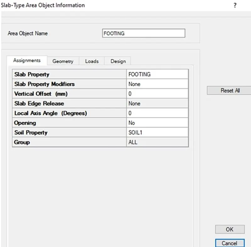
Load is assigned sucessfully
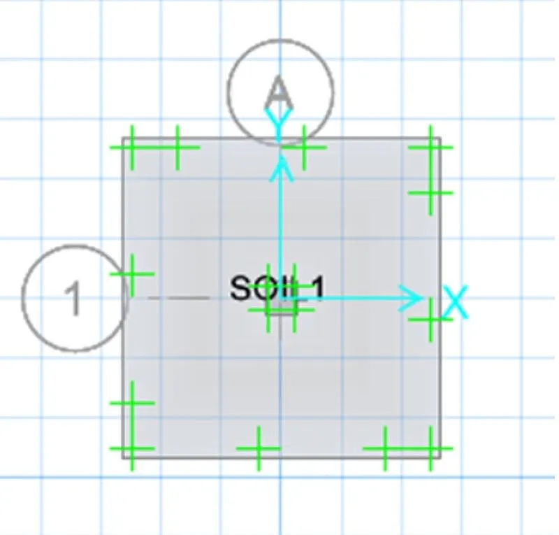
STEP 6:
Assign point load
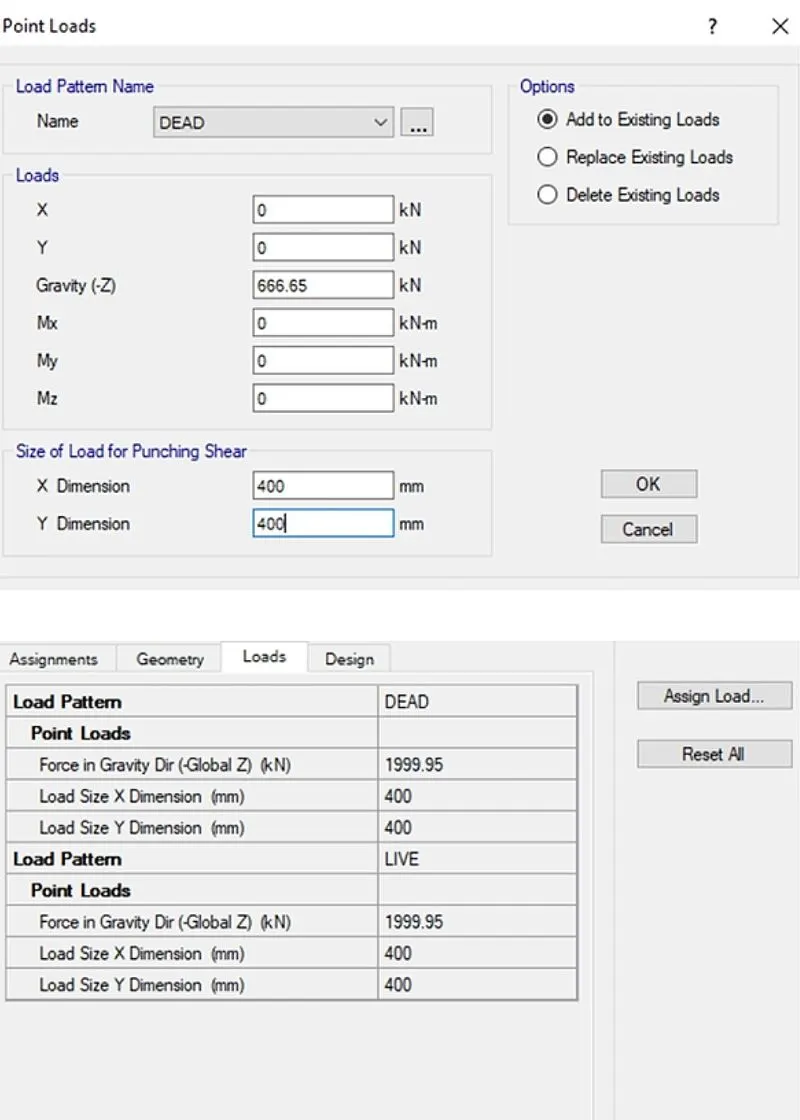
STEP 7:
Assign load combinations
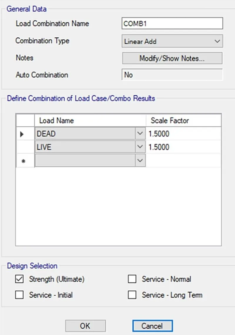
STEP 8:
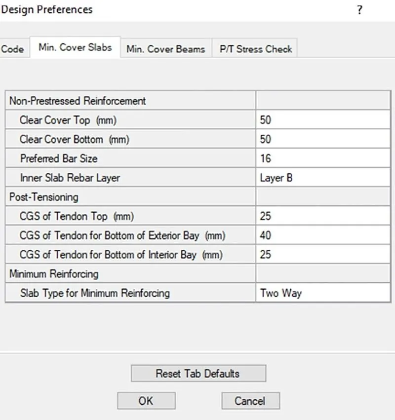
Check design preferences (min cover 50mm)
STEP 9:
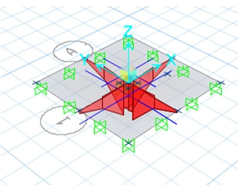
Run analysis and design
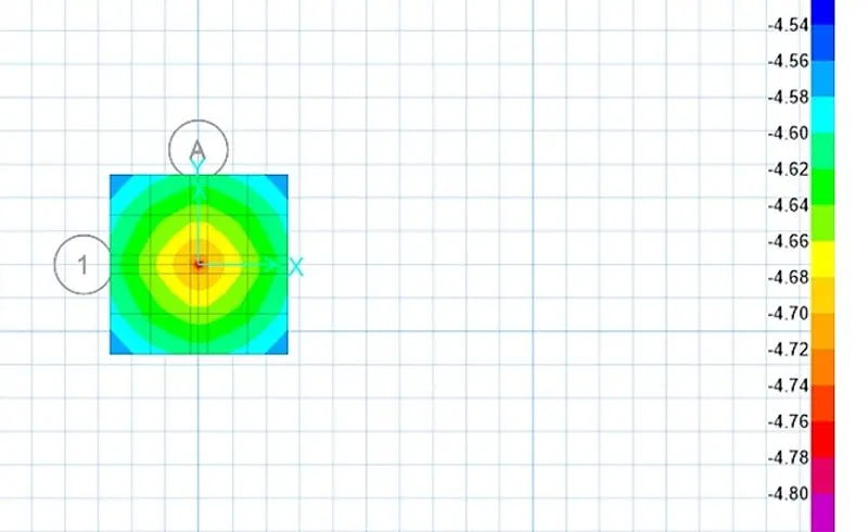
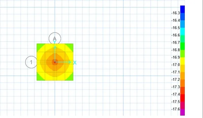
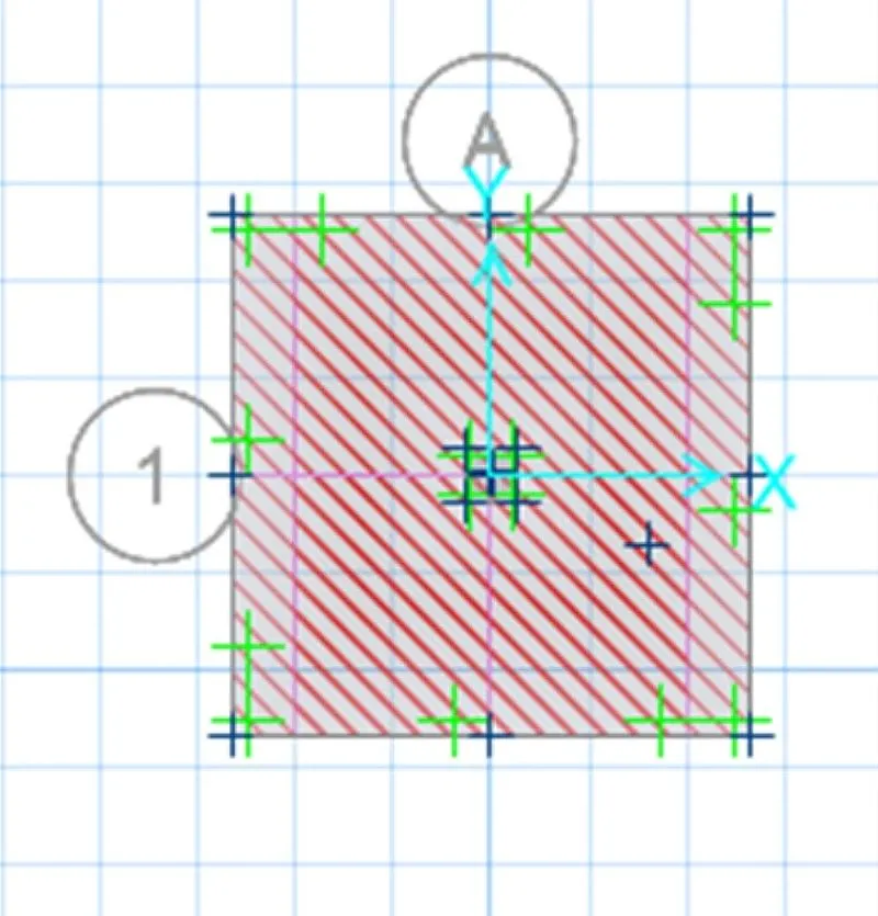
RESULT:
The isolated footing was designed and analyzed in SAFE successfully
2)
AIM:
To model analysis and design the pile cap on SAFE
To evaluate the following:
Pile group to be used
Depth of the pile cap
Longitudnal steel on top and bottom face in both directions
INTRODUCTION:
- SAFE offers a single user interface to perform modeling, analysis, design and reporting.SAFE is ideal for modeling foundations, basemats, and footings. Easily model soil supports and zero tension soil models with uplift analysis. The area assignment of soil supports is based on the subgrade modulus, and they automatically adjust whenever the mesh changes. Basemat foundation models can include pedestals, walls, columns, beams, and piles in addition to the foundation area.
- SAFE includes the ability to define post-tensioning in slabs, as banded or distributed tendons. An interactive tendon editor simplifies the task of laying out the tendon profiles. Tendon layouts can also be automated based on strip position and direction.
- SAFE offers a wide range of code-based design features for reinforced concrete and PT beam, slab design and composite steel beams.
- Deformed geometry can be shown after running the analysis. Values are displayed instantaneously when hovering over the model. The deformed geometry can be displayed as filled or line contour plots.
PROCEDURE:
Open the SAFE application
Select new model
Followed by input settings
Units was selected as metric and code IS 456-2000
50mm each was provided as cover at top and bottom and bar size was defined as 16mm
STEP 2:
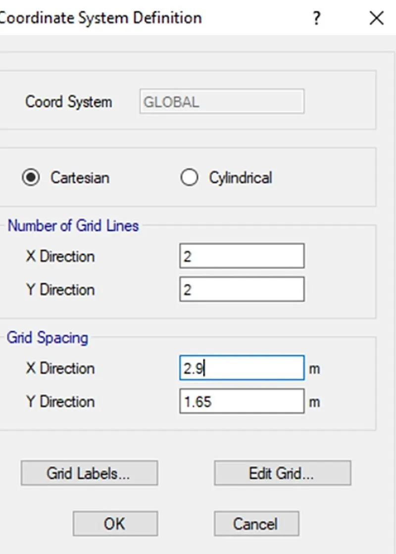
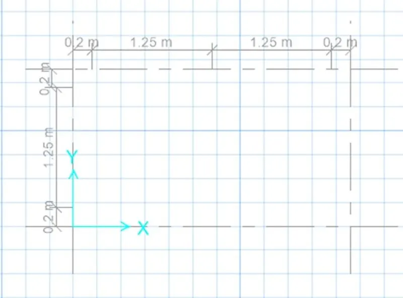
Coordinates are defined next
Grid spacing in x direction and y direction was taken as 2.9 m and 1.65 m respectively
Its shown in below picture
STEP 3:
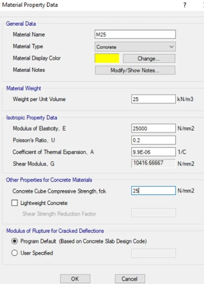
Material property data :
Click define followed by material properties
M25 grade of concrete
Modulus of elasticity
E = root 25 x 5000
=25000N/mm^2
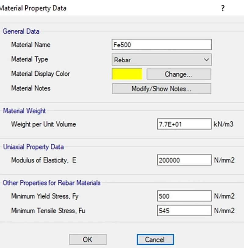
Fe 500 rebar was added next as shown below
STEP 4:
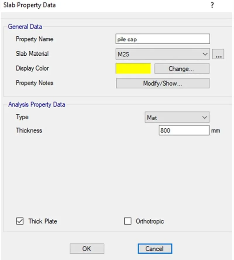
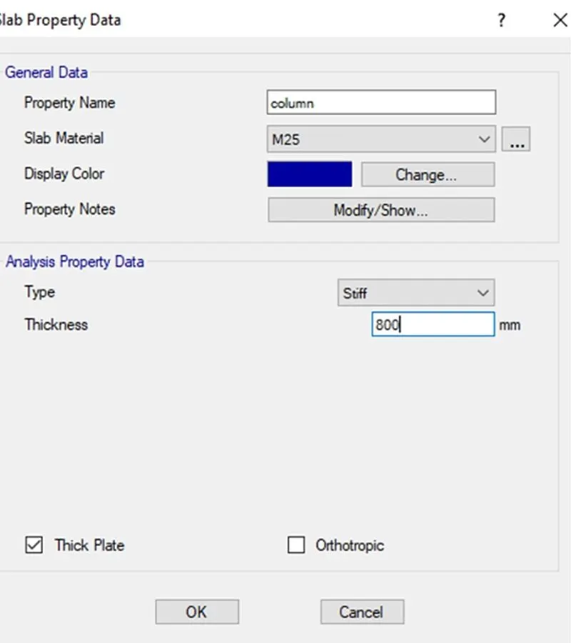
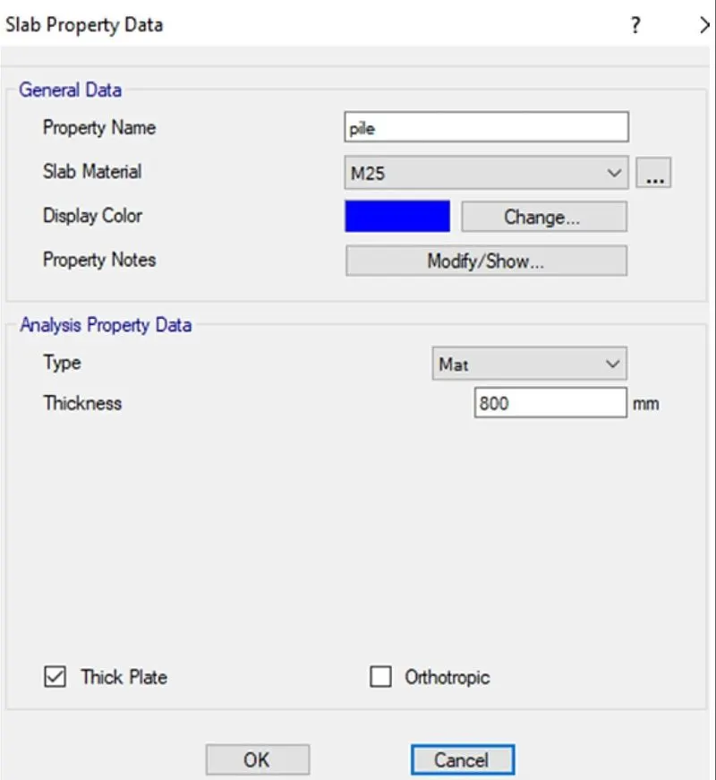
Define slab properties
Define pile cap
Define column
Define pile details
STEP 5:
Draw the slab by using quick draw tool
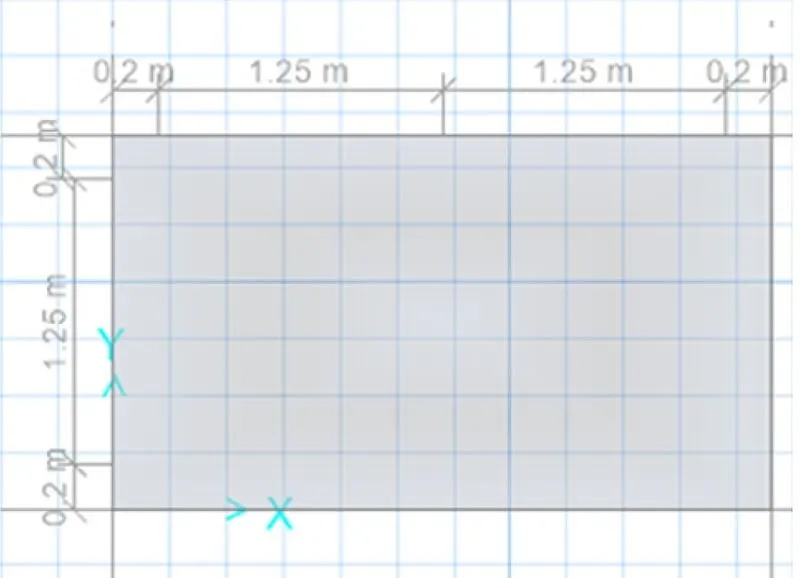
Draw points
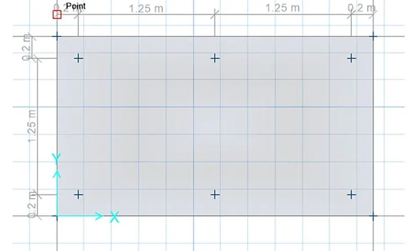
STEP 6:
Add piles at the point
Modify the edge distance to 0.3m
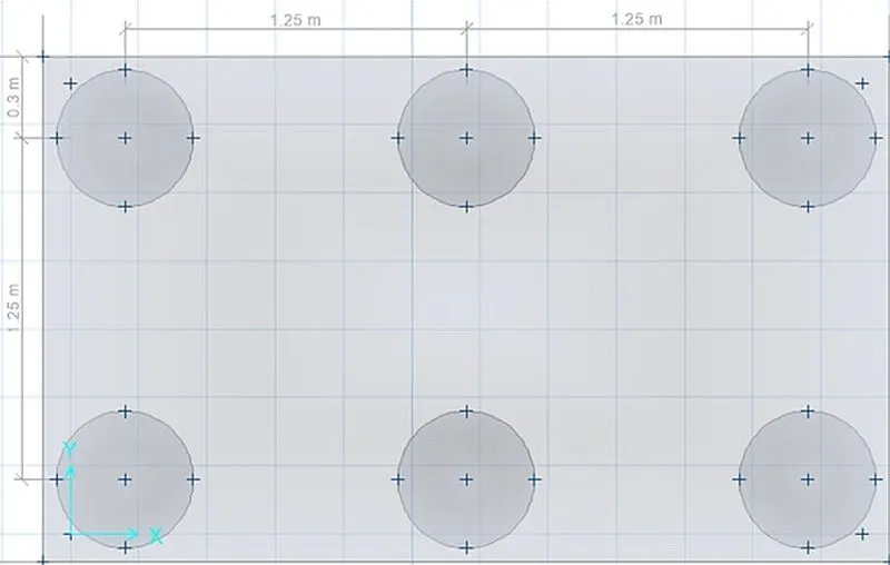
STEP 7:
Create a column of 600mmx600mm
Draw the column in the center using quick draw tool
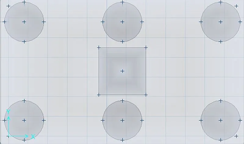
STEP 8:
Springs were added
Select pile<assign<support data<point springs
Springs constant is taken from above calculation
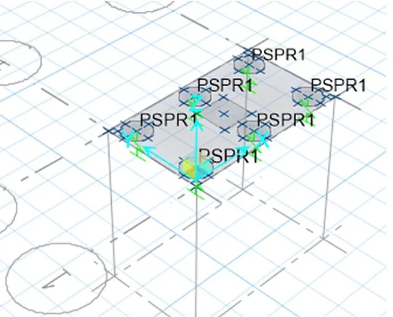
Dead and live load of 587.5KN are added next
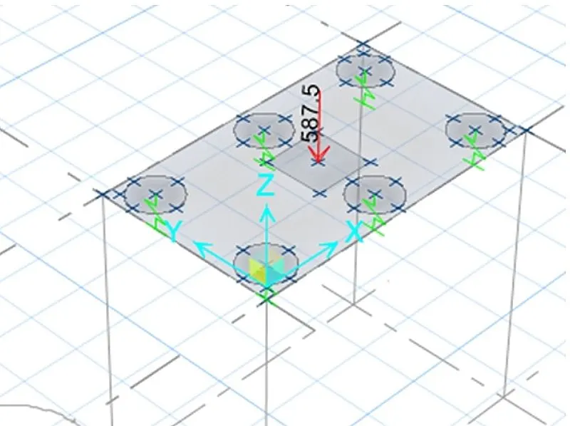
STEP 9:
Load case combination was defined next
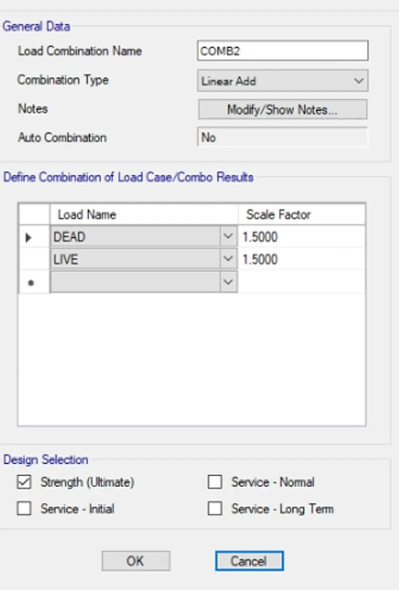
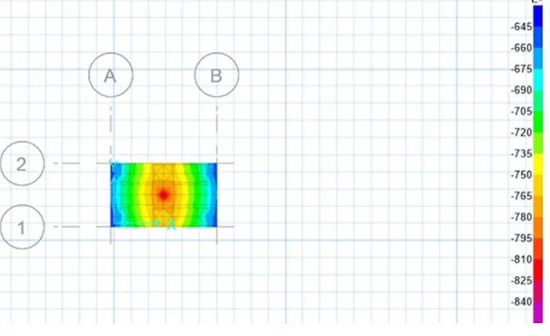
After defining he load combination run the analysis
Max displacement was found to be .84 so its safe
Also all the punching shear values are less than 1
So its safe
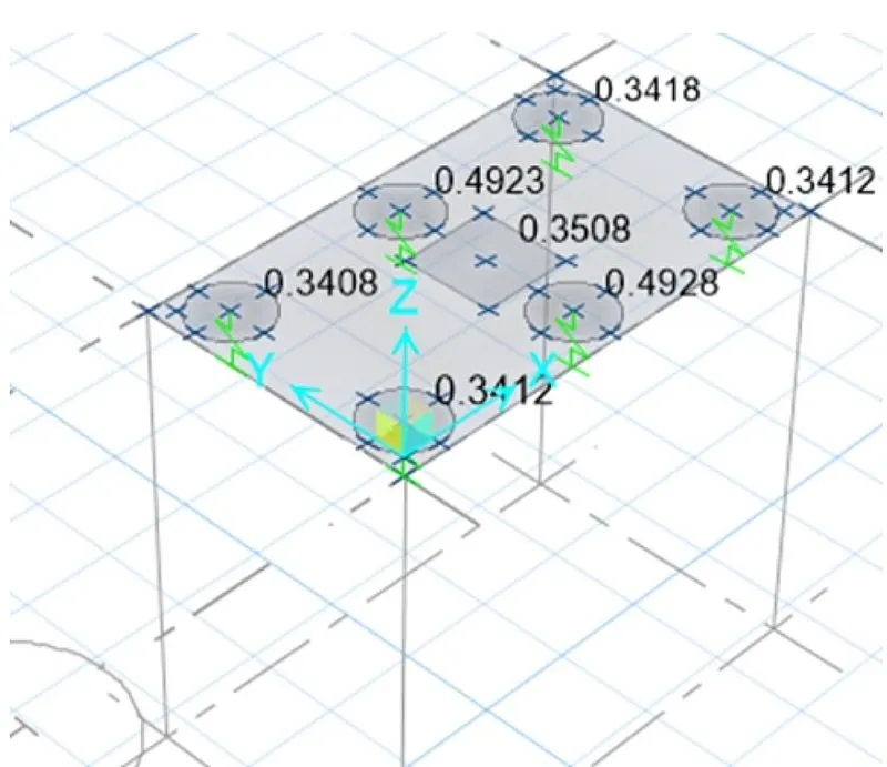
Joint reaction diagram
As all the reaction forces are according to the limit ,its safe
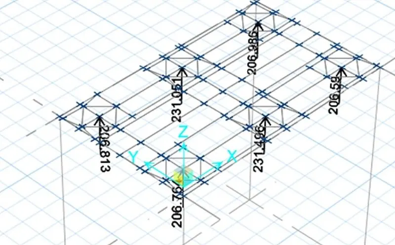
Reinforcement details are added next as shown in both X AND Y direction respectively and run the analysis again
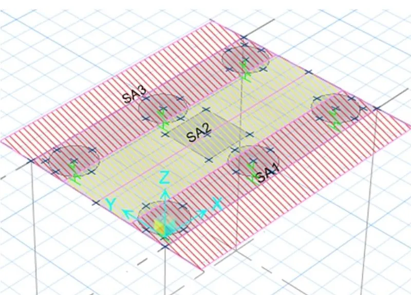
STEP 10:
Reinforcement slab design
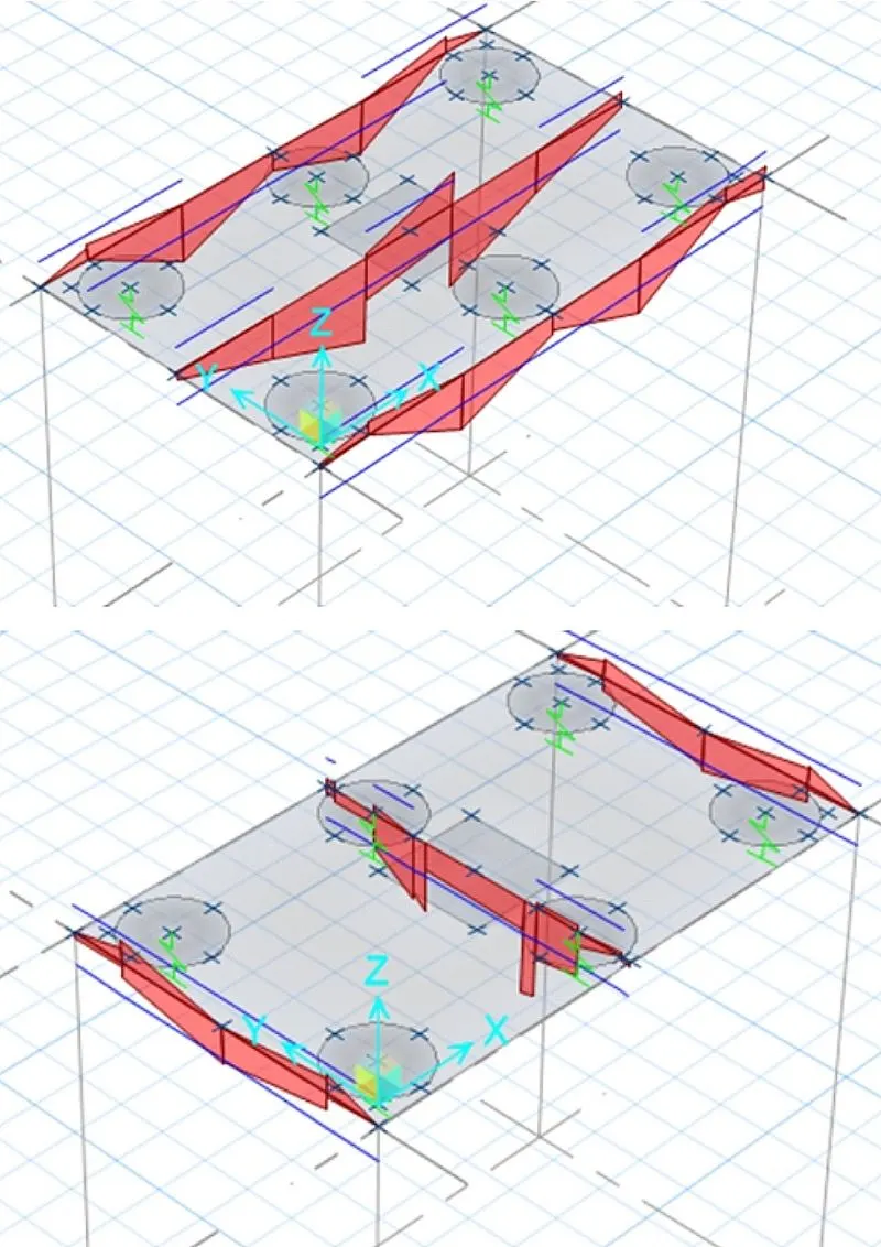
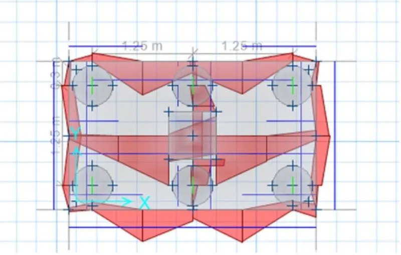
Pile cap foundation design
RESULT:
Complete design of pile cap foundation using SAFE software