Foundation Design using SAFE
AIM:- To design & analysis of Isolated footing using SAFE software.
Procedure:-
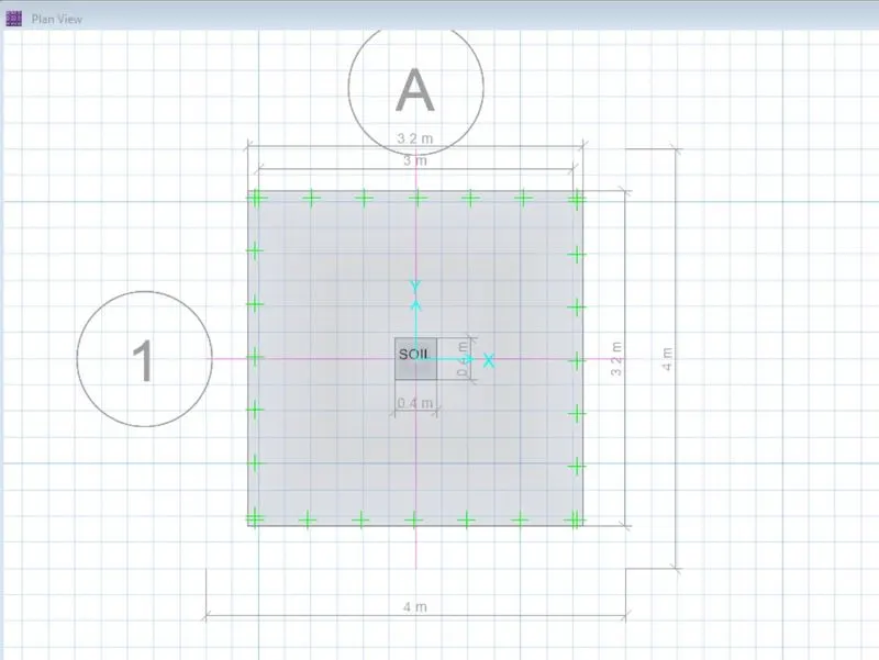
Step 1:- Open Safe software new model - Isolated footing grid - substitute the dimension of footing & column from previous challenge as 3.2m*3.2m & 0.4m*0.4m column size.
Step 2:- Calculate the Soil Subgrade Modulus as = (SBC*F.S of Soil)/Permissible Settlement of footing
we get, (150*3)/0.05 = 9000kn/m2
Step 3:- Assign the soil property by selecting the area of footing.
Step 4:- Assign the loads to the columns by selecting the point on the column.
Step 5:- Calculated load as per previous challenge is 1435Kn (dead & live)
Step 6:- Draw dimension of the footing.
Result:-
Step 7:- Run the analysis
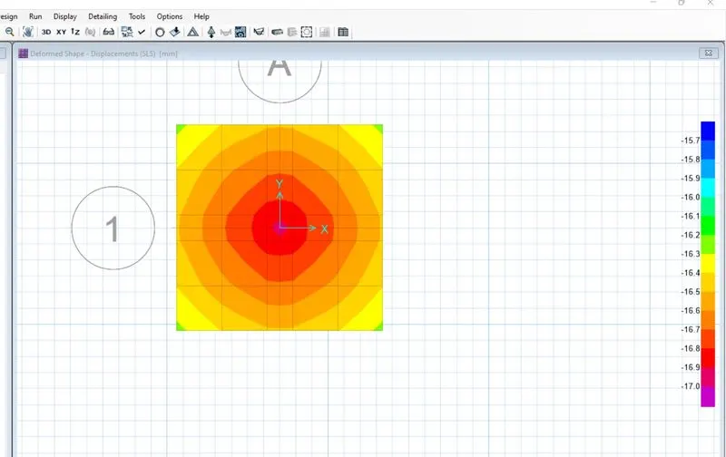
Check for i) Displacement of the footing which has to be less then 50mm.
Result:-
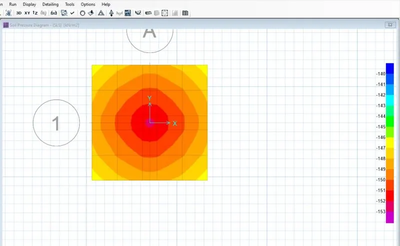
ii) Check for Soil bearing Pressure which has to be less than 150Kn/m2
Result:-
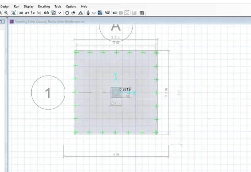
iii) Check for Punching Shear, & there ratio will be less than 1
Result:-
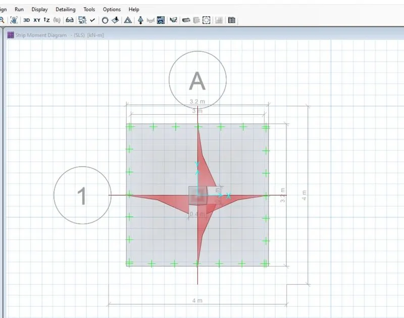
iv) Bending Moment Diagram.
Result:-
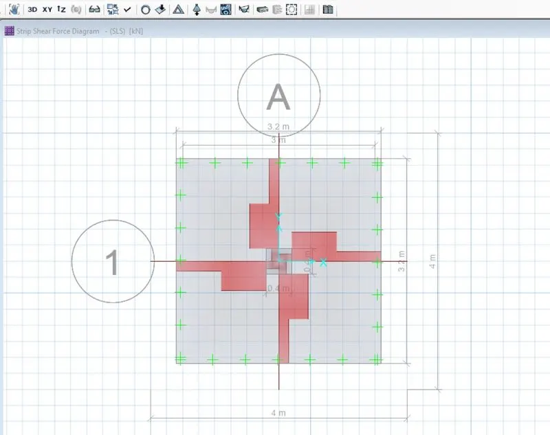
v) Shear force diagram
Result:-
Step 8:- Design the strip along A & B layer in footing
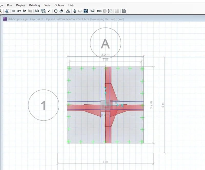
Step 9:- Slab Design- as per Strip based & impose minimum reinforcing steel, which impies minimum amount of steel in bottom or top reinforcement.
Result:-
Answer 2.
AIM:- To design & analysis the Pile footing by using SAFE software.
Step 1:- Open Safe software - new model - Blank footing grid
Calculate the no. of Pile as = Unfactored load with self weight/individual pile capacity
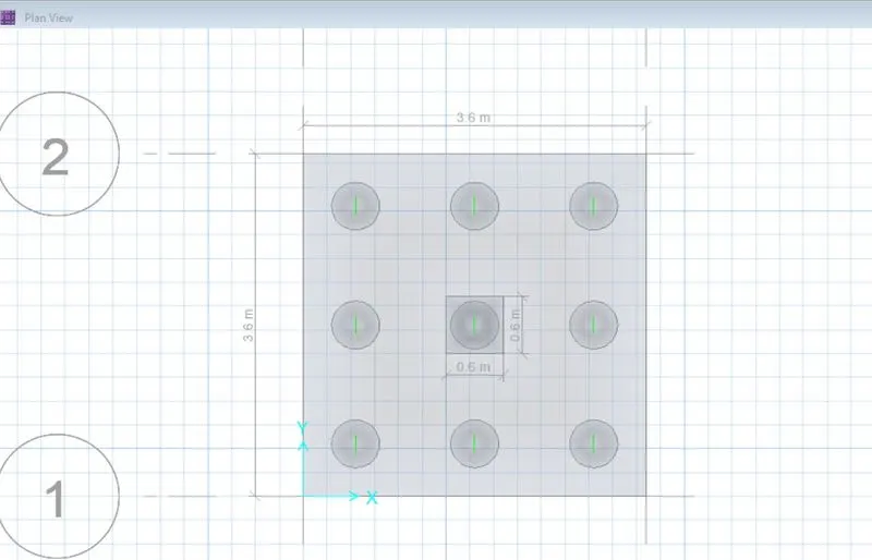
we get, 7 say, 9 no of piles
Take c/c distance b/w pile is 2.5*dia of pile = 2.5*500=1.25m
Edge distance of pile is = 300mm
Step 2:- Define materials properties such as Concrete & Rebar
Step 3:- Define Slab Properties such as
Pile_Cap
Piles
Stiff(Column)
Result:-
Step 4:- Assign Spring point to the piles
formula:- Spring Constant= E*A/L where, E= Modulus of Concrete
A= Area of pile, (3.14*d2)/4
L= Length of pile
we get, S= 335.9Kn/mm
Step 5:- Assign load to the Column
Step 6:- Run the Analysis
Step 7:- Design the Strips along A & B layer.
Step 8:- Check for
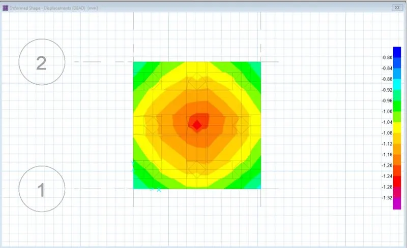
i) Displacement of the pile
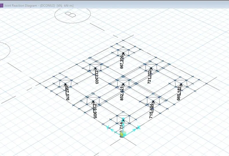
ii) Reactions of the soil
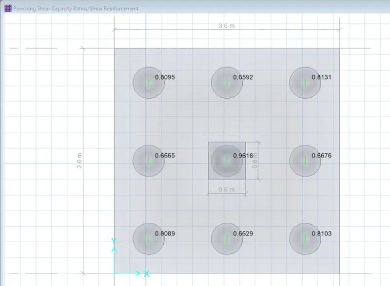
iii) Two Way Shear or Punching Shear
The maximum limit for two way shear is 1.
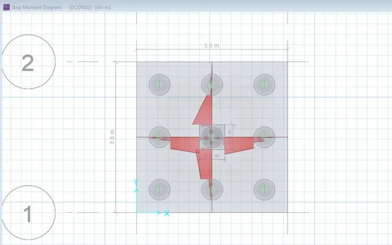
iv) Bending Moment Diagram
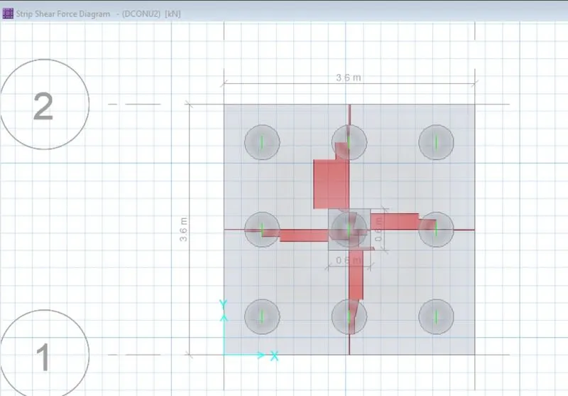
v) Shear Force Diagram
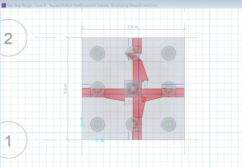
Step 9:- Slab Strip Design or Area of Reinforcement