Foundation Design using SAFE
AIM:
To design the given an isolated footing in Week 11th challenge with the help of safe software and to know the general procedure of spread footing with safe software
INTRODUCTION:
Modalled the isolated footing on SAFE, analysed and design it to verify the size, depth and steel procedure of the calculation is provided
PROCEDURE:
STEP 1) Open SAFE
- Install the SAFE software from CSI Website
- After complete the installation, Launch SAFE software from windows
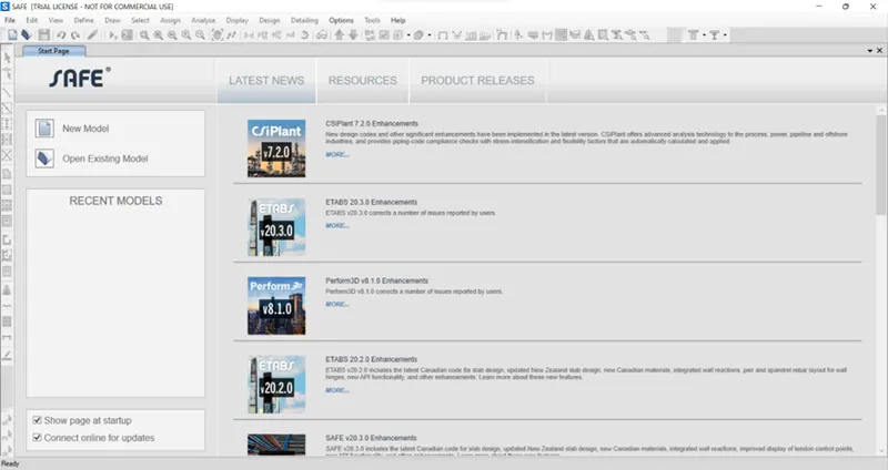
- SAFE home interface will be open as shown below

STEP 2) Create New Modal
- Form the safe software home interface select new modal
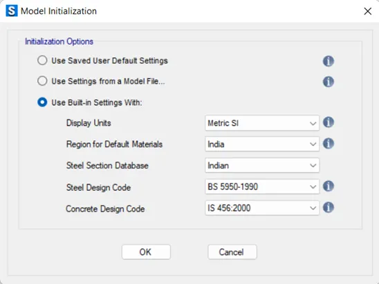
- Select Unit Built in Setting from Modal Initialization dialog box
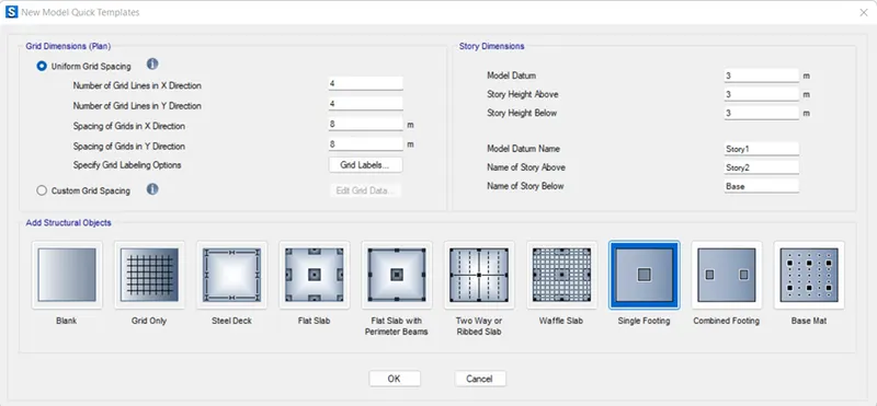
- Click on single footing from New Modal Quick Templates
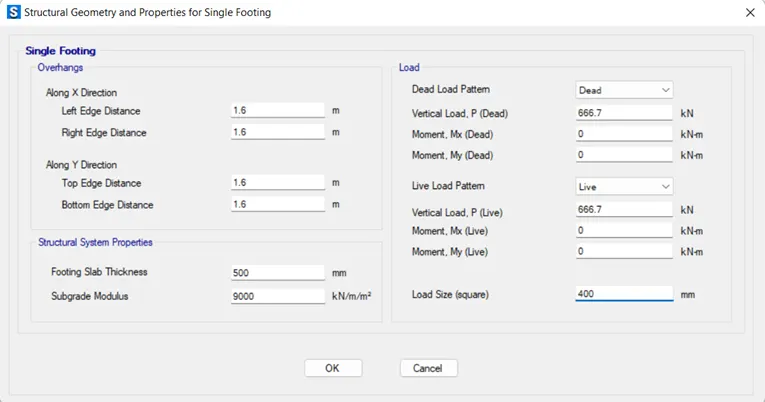
- Enter the values like size of footing, column, thickness and modulus
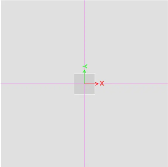
- Footing is ready in user window of SAFE
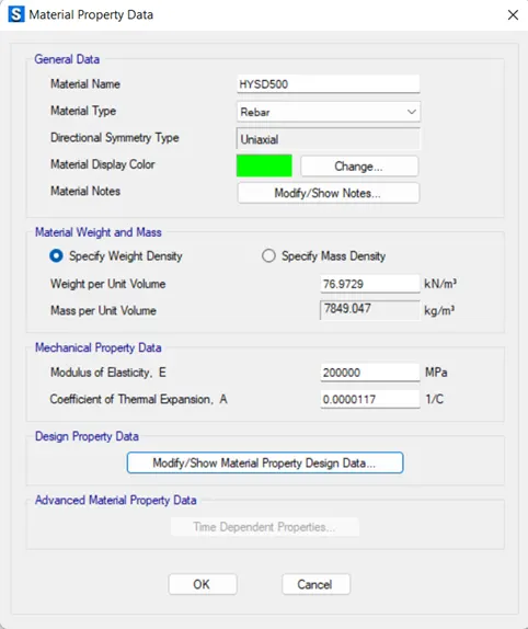
STEP 3) Define Material Properties
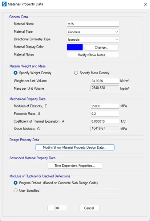
- Add new material as concrete grade of M25 and Rebar as fe500
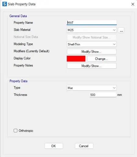
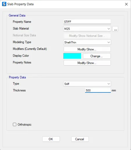
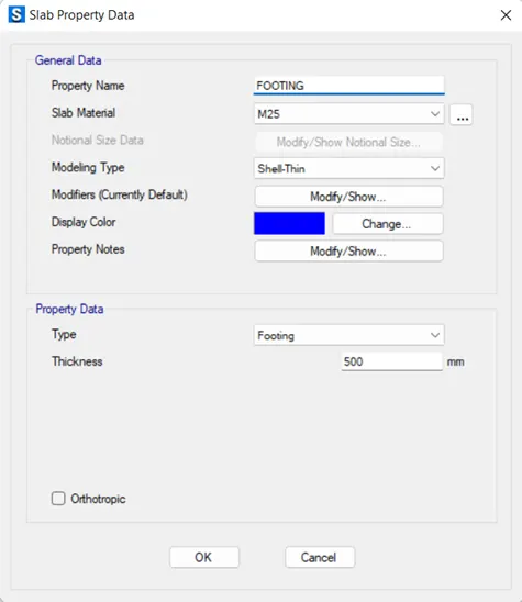
STEP 4) Define Section Properties
- Add section property as a FOOTING, MAT and STIFF with thickness of 500
STEP 5) Define spring property
- Form define go to spring properties select area spring and add
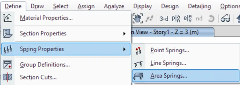
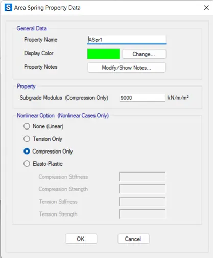
STEP 6) Load Pattern
- Form define go to load pattern add dead load and live load
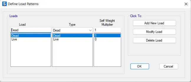
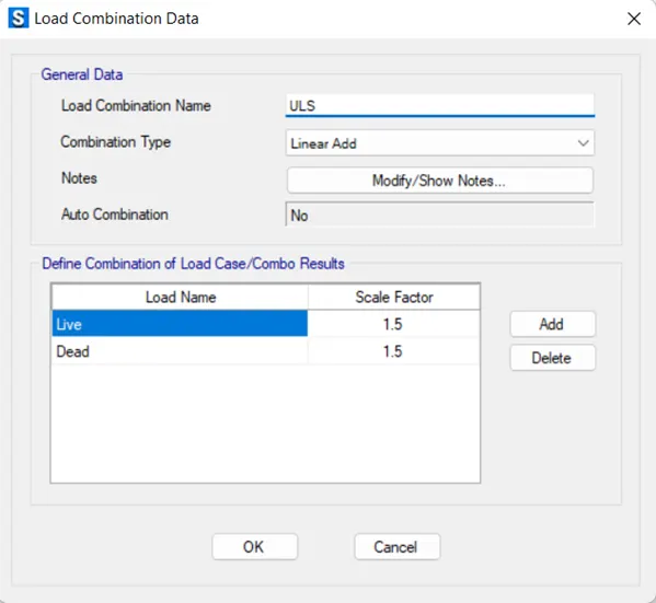
STEP 7) Load combination
- Serviceabilty limit state unfactored dead & live load as 1
- Ultimate limit state factored dead & live load as 1.5
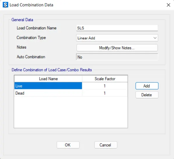
STEP 8) Assign area load on footing
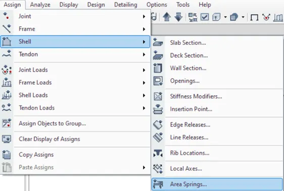
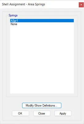
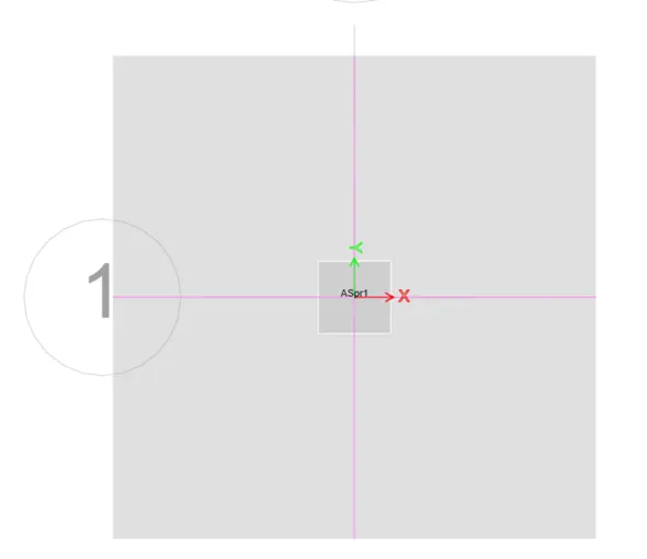
- Select the footing then assign area spring load
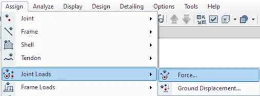
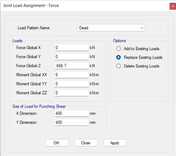
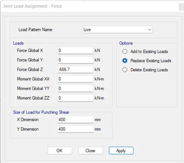
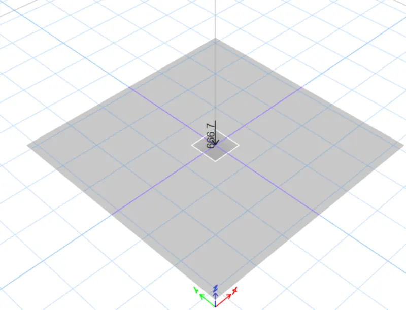
STEP 9) Assign Joint Load On Column Point
- Select the point of column and assign the dead load and live load
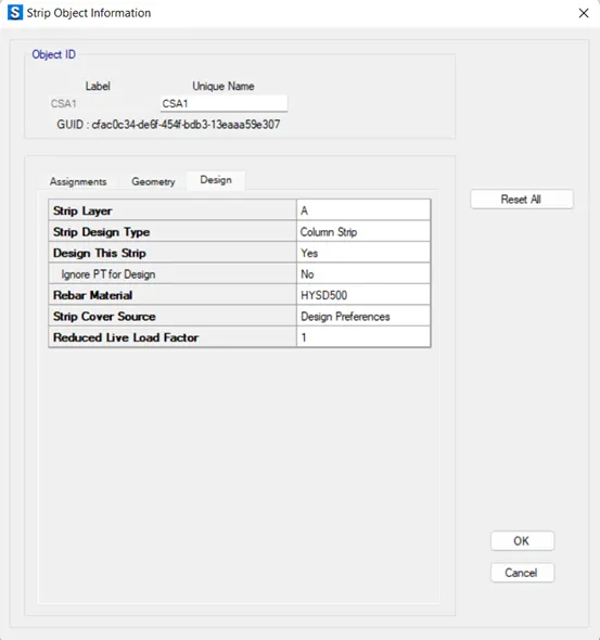
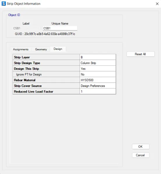
STEP 10) Design Strip
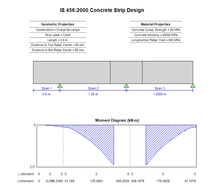
- Select X & Y direction strip and right click to assign the strip
STEP 11) Run Analysis
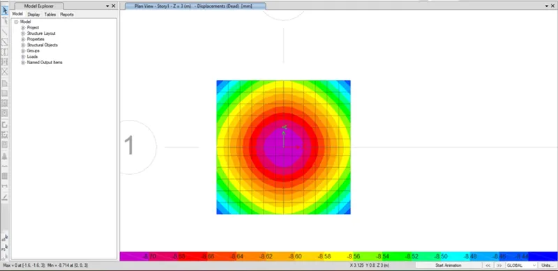
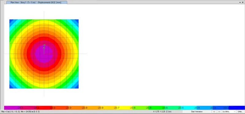
- The modal show the maximum deflection which is allowable
STEP 12) Checks need to be performed in SAFE analysis
1. Safe bearing capacity under service load
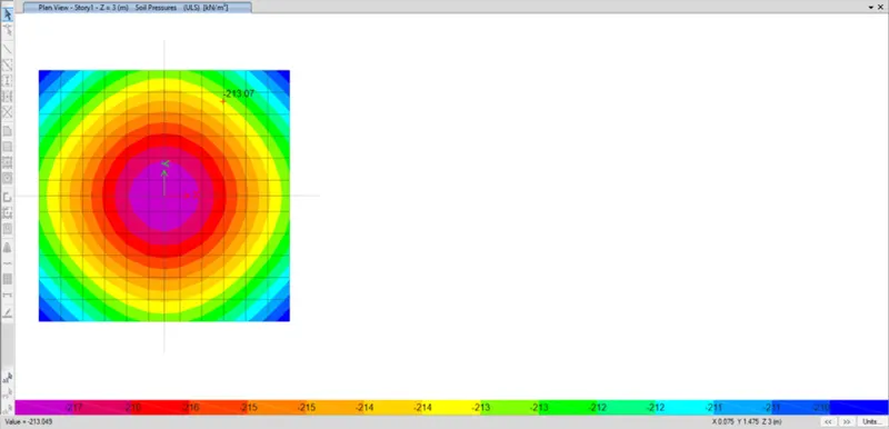
2. Settlement under service load
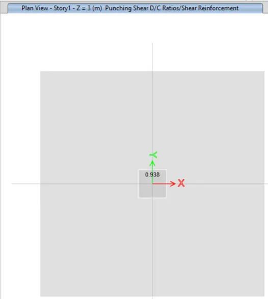
3. Two way shear check punching shear
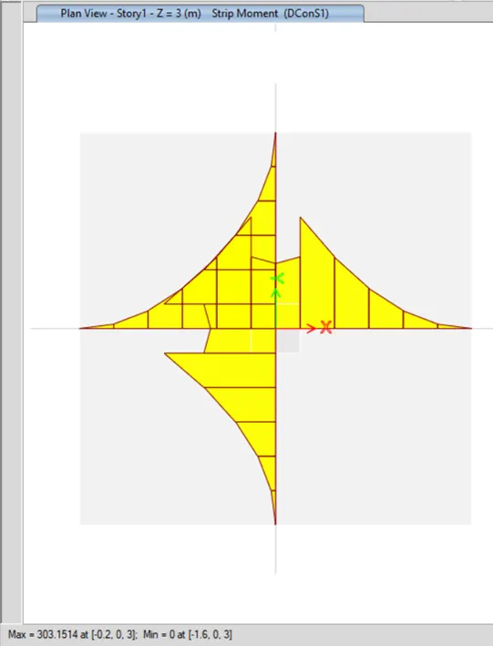
4. Ultimate bending moment and shear
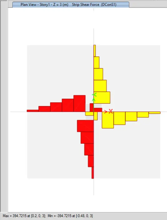
5. Flexural reinforcement design for footing slab
2. A column of size 600x600 carrying an unfactored gravity load (DL+LL) of 1175 KN is to be supported on pile cap, which ultimately transfers load to the piles underneath. Piles of 16 metres length and 500 mm diameter are to be used. Each pile has a load carrying capacity of 200 KN. Model, analyse and design the pile cap on SAFE to evaluate the following:
- Pile group to be used
- Depth of pile cap
- Longitudinal steel on top and bottom face in both directions
DESIGN OF PILE FOUNDATION
AIM:
To design a pile foundation with given criteria and to know the general procedure of pile foundation with SAFE software
INTRODUCTION:
Modalled the pile foundation on SAFE, analysed and design to obtain the result
Given data-
Column size = 600 x 600
Axial load (Unfactored load) = 1175kN
Pile length = 16m
Loading capacity of each pile is = 200kN
Data Required for the Safe Analysis and Design-
Dead load breakup = 1175/2 = 587.5kN
live load breakup = 1175/2 = 587.5kN
no of pile = axial load/ capacity of single pile = 1175/200 = 5.8 = 6 pile required
so that area of pile = 3.14x500^2 = 196349m^2
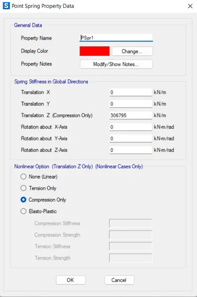
point spring of pile = (AXE)/L=(196349X2500)/16000 = 306796 kN/m
min. spacing b/w pile = 2.5D = 2.5 x 500 = 1250mm
edge distance = 200mm
PROCEDURE:
STEP 1) Create a Modal
- Form the safe software home interface select new modal
- Select Unit Built in Setting from Modal Initialization dialog box
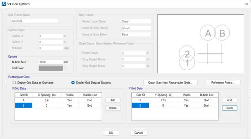
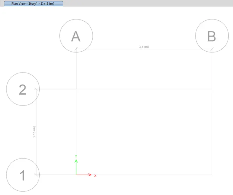
- Create grid for modal
- Foundation is ready in user window of SAFE
STEP 2) Define Material Properties
- Add new material as concrete grade of M25 and Rebar as fe500
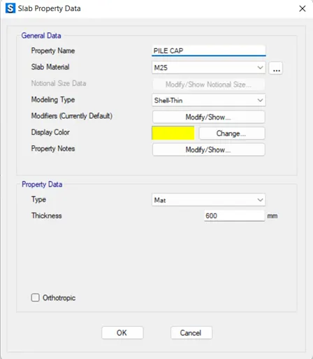
STEP 3) Define Section Properties
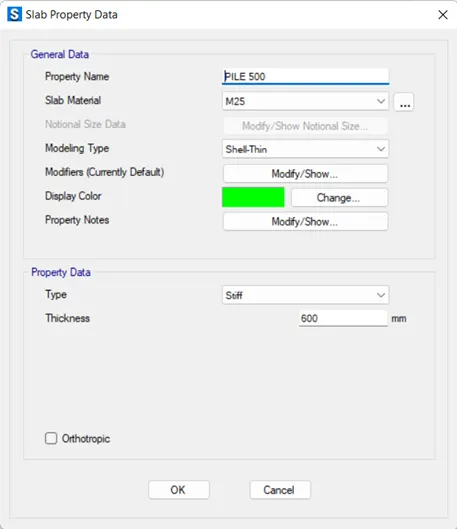
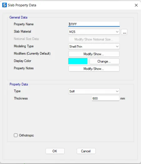
- Add section property as a PILE CAP, PILE and COLUMN STIFF with thickness of 500
STEP 4) Define Point Spring
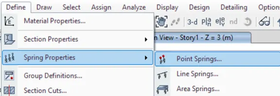
- Form define go to spring properties select Point Springs and add
STEP 5) Load Pattern
- Form define go to load pattern add dead load and live load
STEP 6) Load combination
- Serviceabilty limit state unfactored dead and live load
- Ultimate limit state factored dead and live load
STEP 7) Draw Plie Cap, Plie and Column Stiff
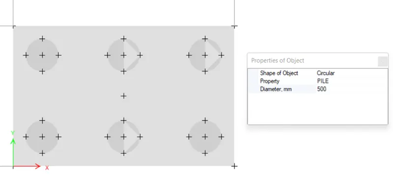
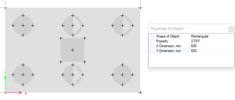
- Select draw slab tool and change property as plie cap then draw the slab
- For pile, first draw the joints (points) with taken offset and replicate for other
- Select tool quick draw area around point then change the property & dimension and click on points similarly for column stiff
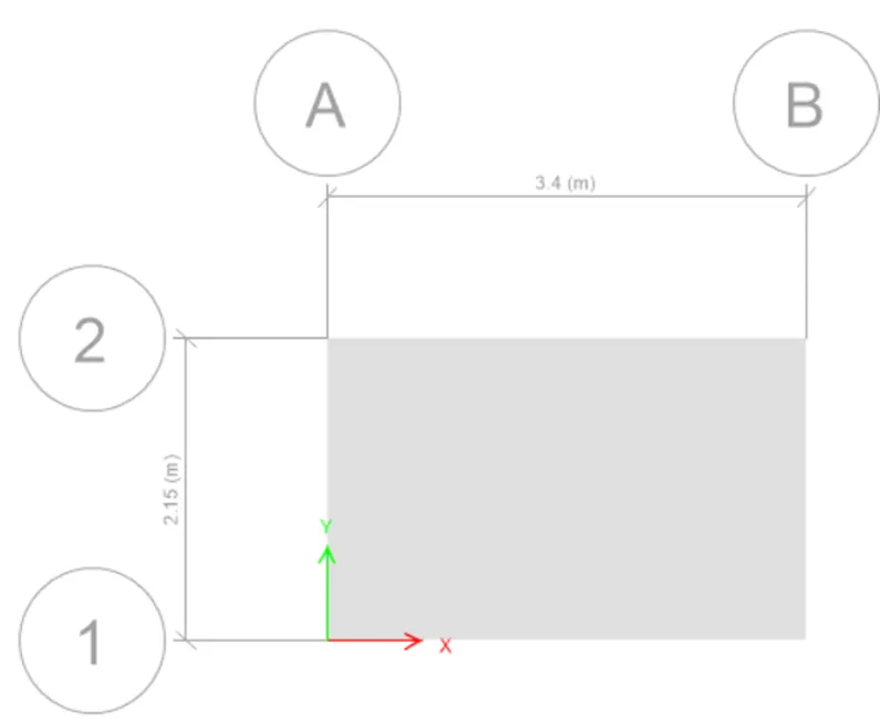
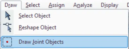
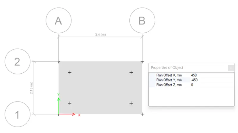
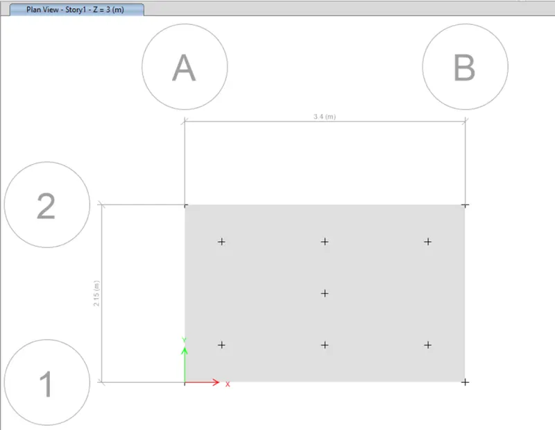
STEP 8) Assign spring on Pile
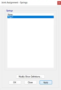
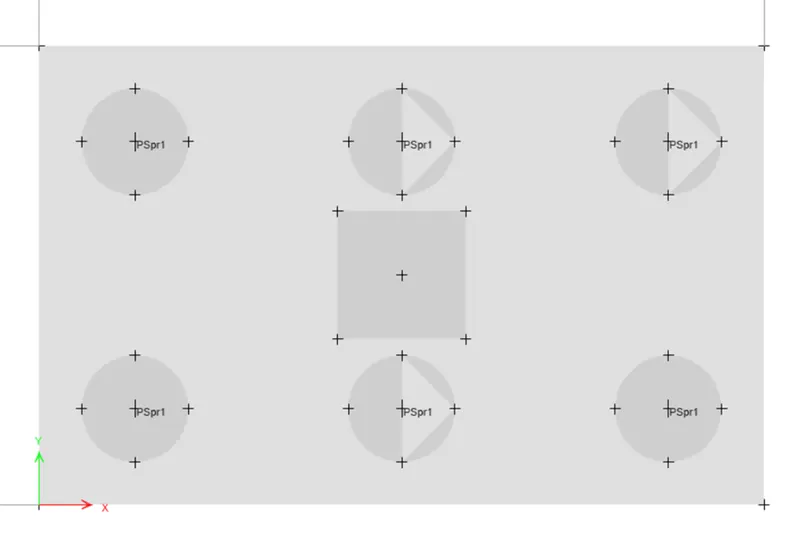
- Select the center point of plie then assign point spring load

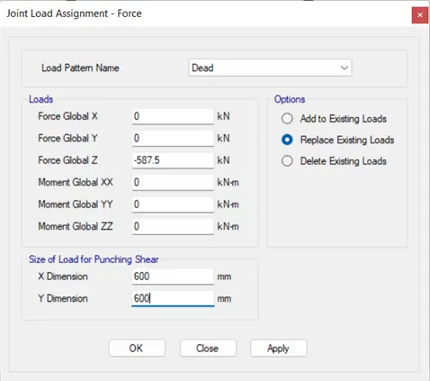
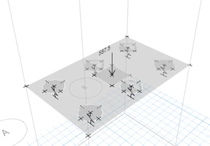
STEP 9) Assign Joint Load On Column Point
- Select the point of column and assign the dead & live load
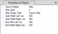
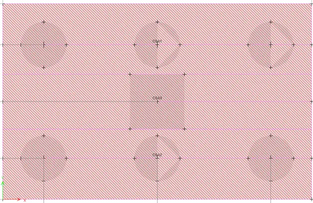
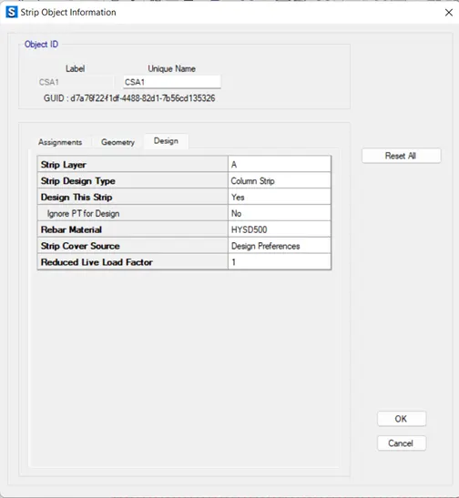
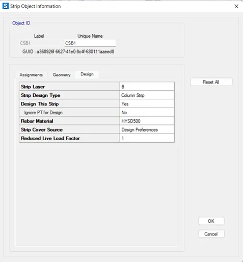
STEP 10) Design Strip
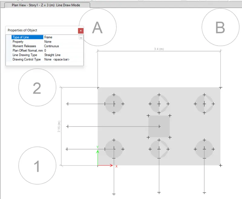
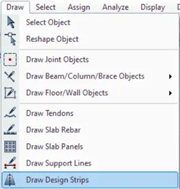
- For strip design, first we have to create a reference line by choosing draw line with none property later delete that line
STEP 11) Run Analysis-
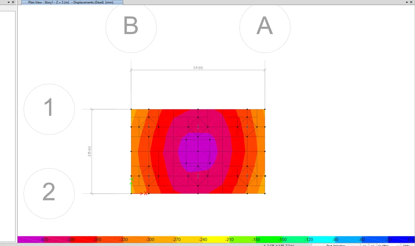
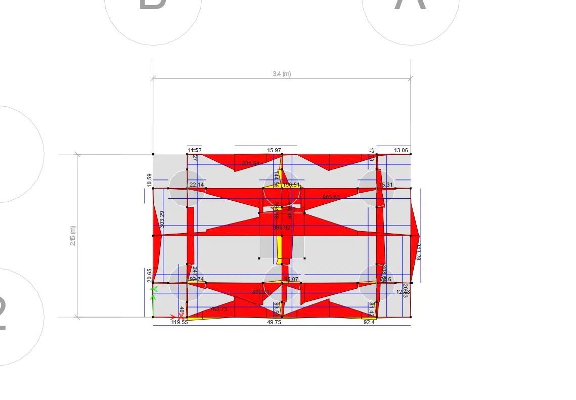
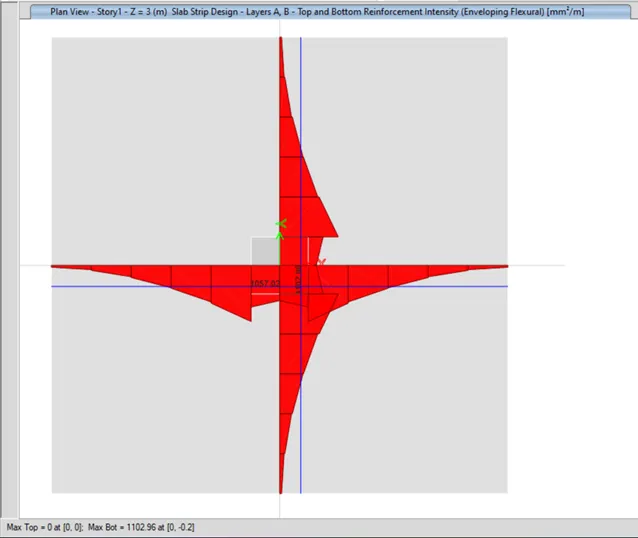
STEP 12) RESULT-
Checks need to be performed in SAFE analysis
1. Individual pile capacity under service load
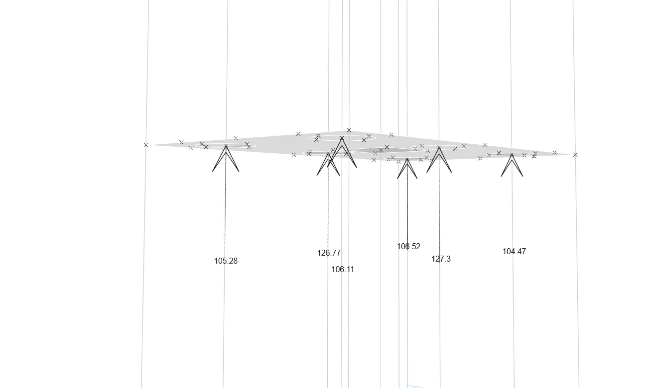
2. Settlement under service live
3. Two ways shear check (punching shear)
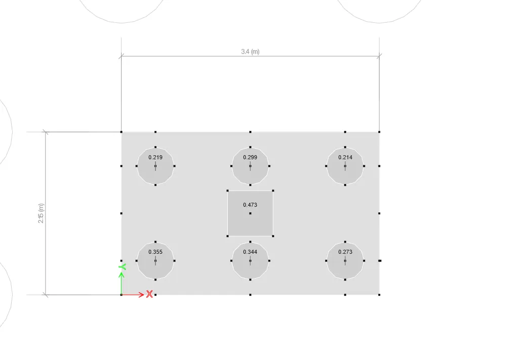
4. Flexural reinforcement design for footing slab