Foundation Design using SAFE
AIM-
- TO model the isolated footing provided in week 11 on safe
- to analayzwe and design it to verify the size
- to model the pile cap on safe.
PROCEDURE
step 1
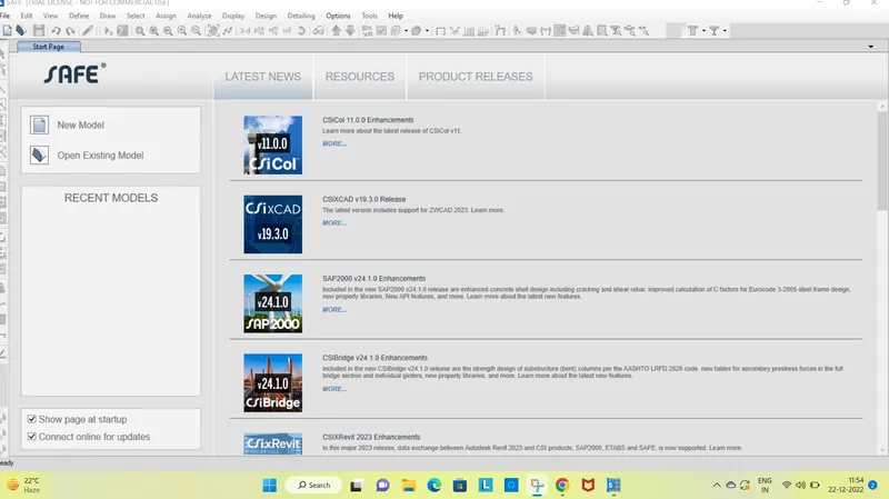
- open safe software
- click on the new model
STEP 2
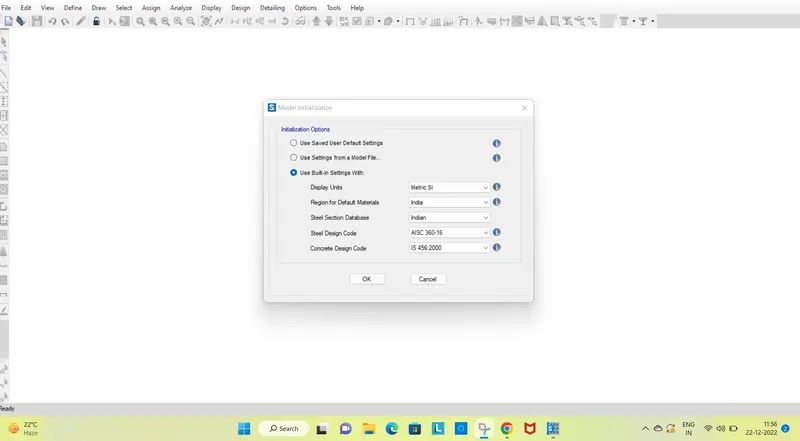
- once you click on new model
- a following dialog box will opwn
- provide the neccery data
step 3
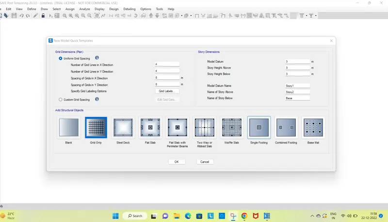
- once you click okey
- model templete box will open
- click on single footing
step 4
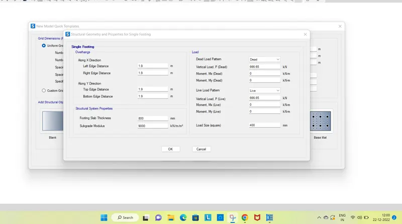
enter the dimension as per the calculation we have done in week 11 challlenge
step 5
- once you click ok
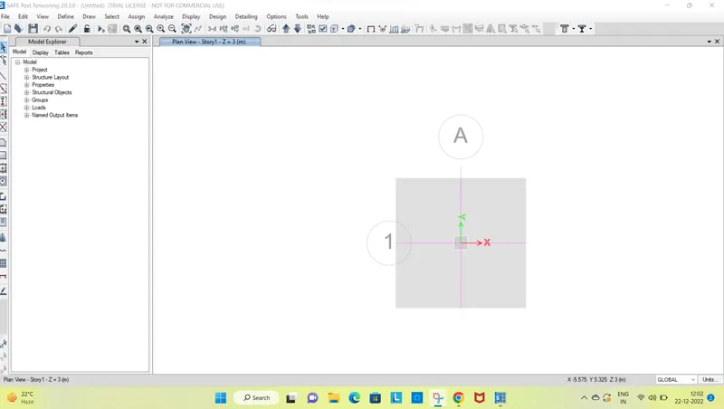
- you will see the geometry is created in model spaces as follos
step 6
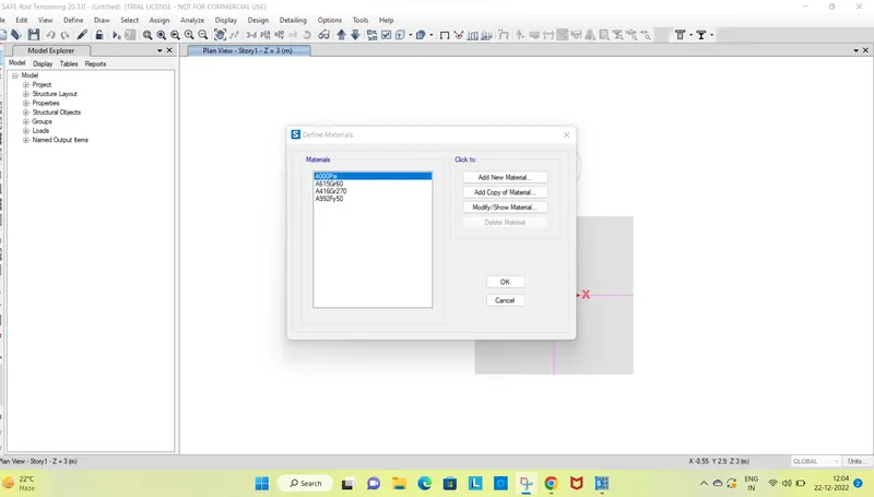
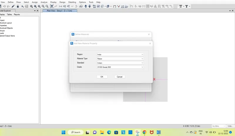
- now we have add material properties
- click on define
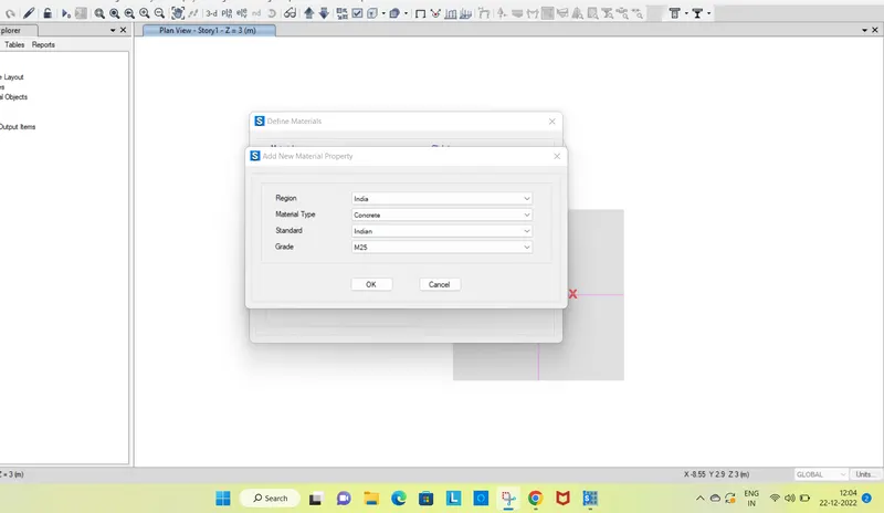
- click on add new material
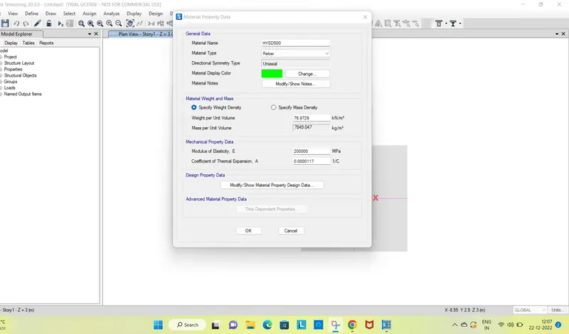
- one you click add new material add the following parameter
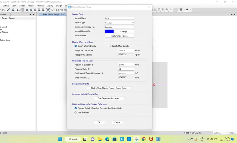
click on ok
similerly add the rebar properties
step 7
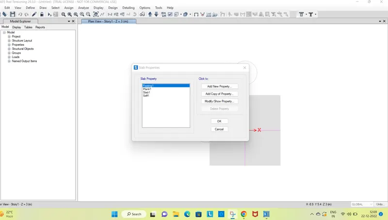
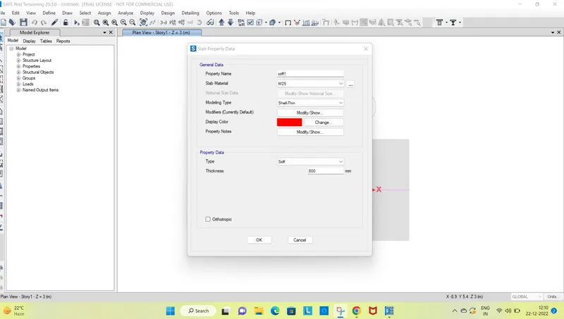
now we have to define slab properties
as we already define slab properties in grid section
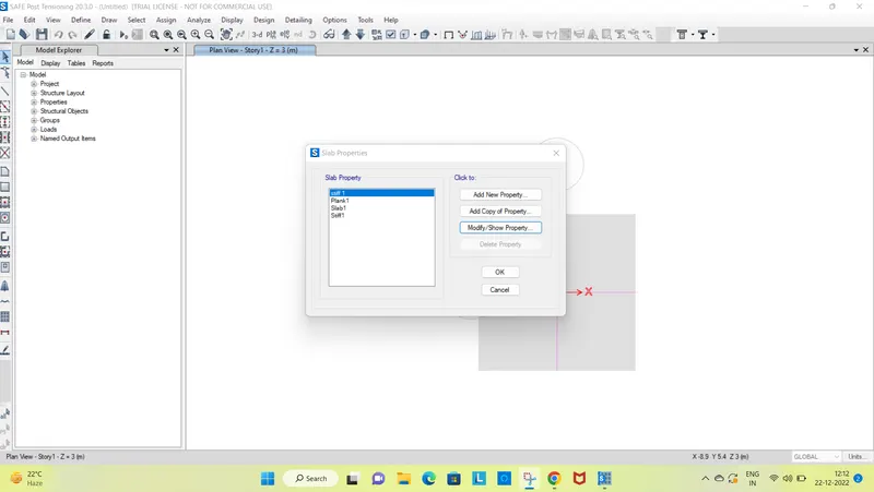
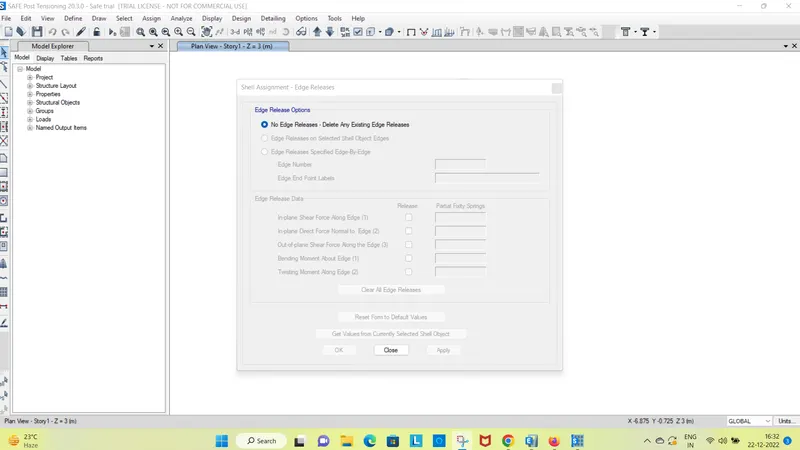
step 8 now we have to assign soil properties
define soil properties
STEP 9
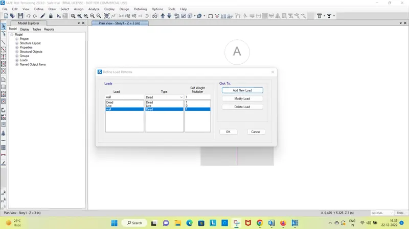
now we have to cheak if load are defined or not
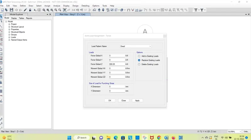
STEP 10
NOW we have to define the load combination
for that define- load combination
STEP 11 -
- NOW RUN the model
- click on the run analysis
- save rhe file
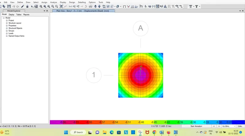
- now you will see the displacement
- click on deformed shape - selct combination as - SLS and see displacement
- as displacement is - 12 mm which is less than 25mm ...safe
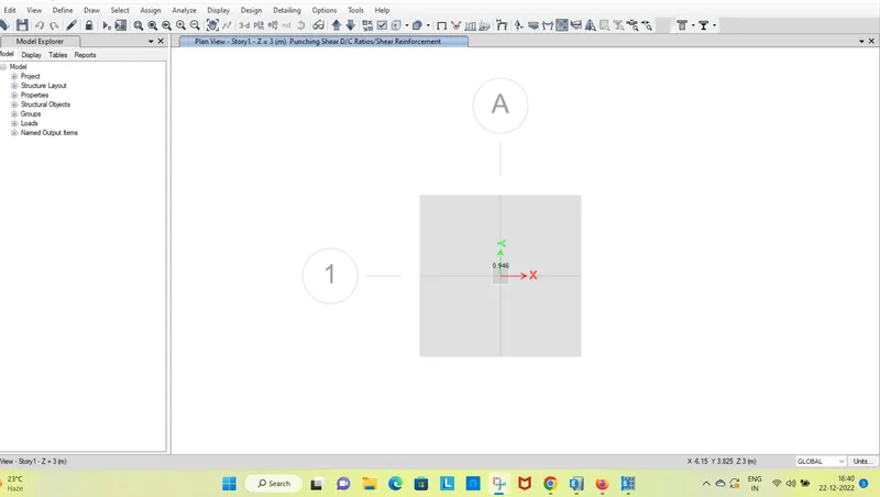
- cheak for punching shear
- click on diplay - punching shear
- as we can see that punching shear is less then 1
- 0.956<1 ... safe
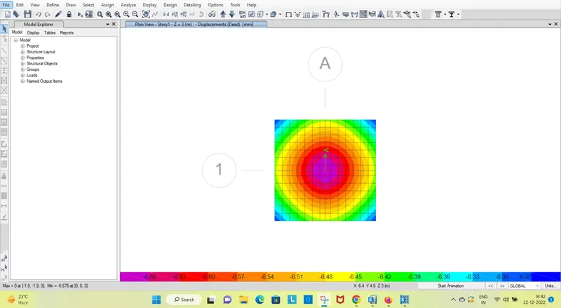
CHEAK FOR DIPLACEMENT
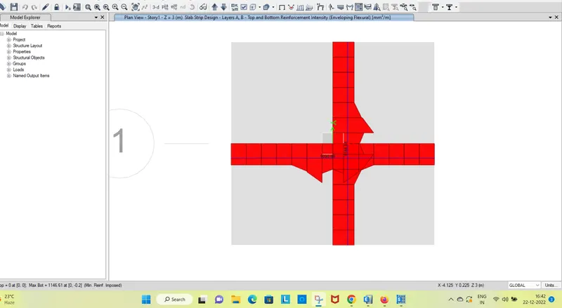
FIND OUT AREA OF REINFORCEMENT
RESULTS
- isolated footing is designed for square column of size 400*400mm
- we have to provide footing size as 4m*4m
- bearing soil pressure is cheaked and found ro be safe
- punching shear rtio is cheak and found to be safe
Q 2)
AIM- to model analyse and design the pile cap on safe
PROCEDURE-
step 1.
step 1
- open safe software
- click on the new model
STEP 2
- once you click on new model
- a following dialog box will opwn
- provide the neccery data
step 3
- once you click okey
- model templete box will open
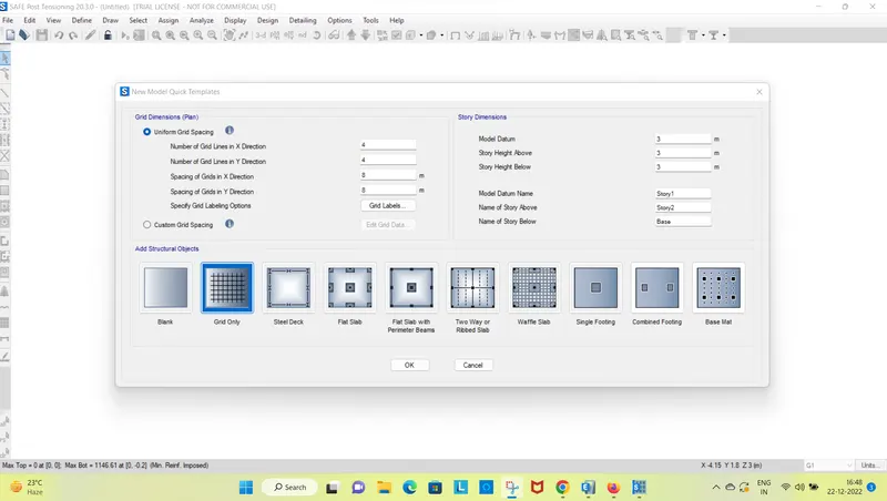
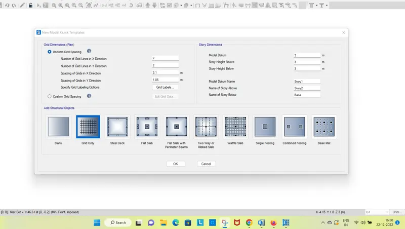
- click on grid only
- enter no of grids in x directiom and y = 2
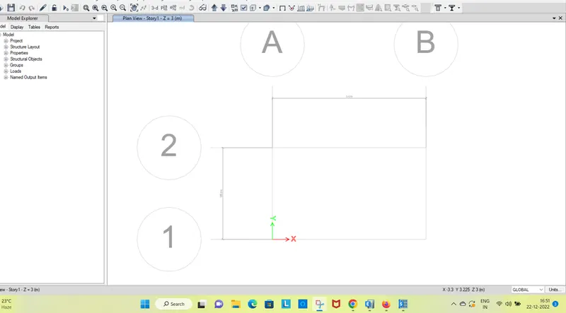
- enter spacing in x = 3.1m
- enter spacing in y = 1.85 m
- S
STEP 5
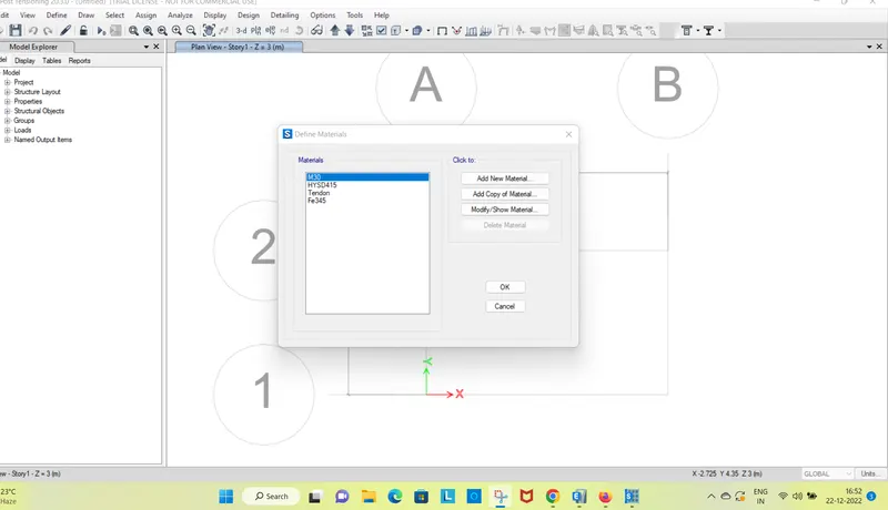
now we have to assign the material
define - material properties
click on add new mmaterail
STEP 6
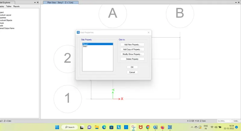
- now we have to define slab properties
- in pile cap we have to define 3 slabs
- footing
- for column
- for pile cap
step 7.
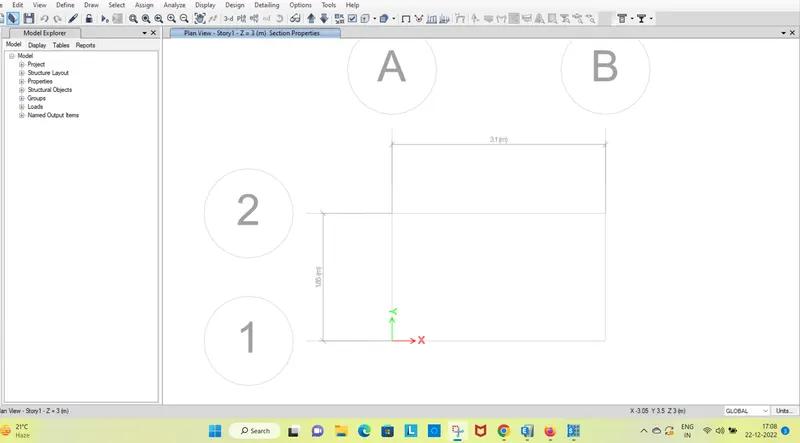
- once slab properties are defined
- now we have to start the modelling
- select quick draw slab option
- draw the slab select footing as property
step 9
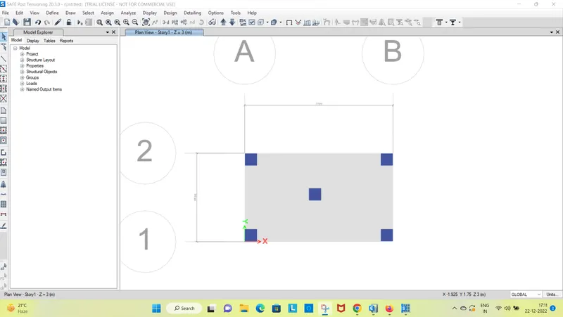
- now we have to add column slab
- click on quick draw area
- slect the property
- draw the cloumn
- draw pile cap
step 10
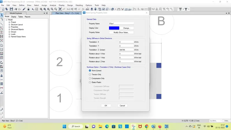
- now we have to add spring to the pile beacause it behave like a spring
- click on assign - suppot data- point spring
- spring constant from above calculation is taken as
- add sproing constant - 306795kn/m
- select compressive only
step 11
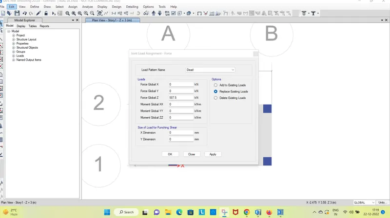
- now we to add the load
- go to assign - joint load - point load
- assign 587.5 kn live load
step 12
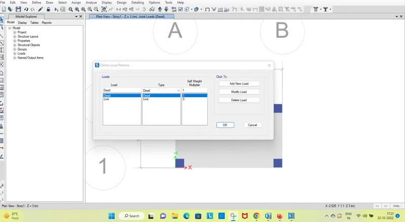
now we have to add load combination
define - load combination
define the load combination as follow
step 13
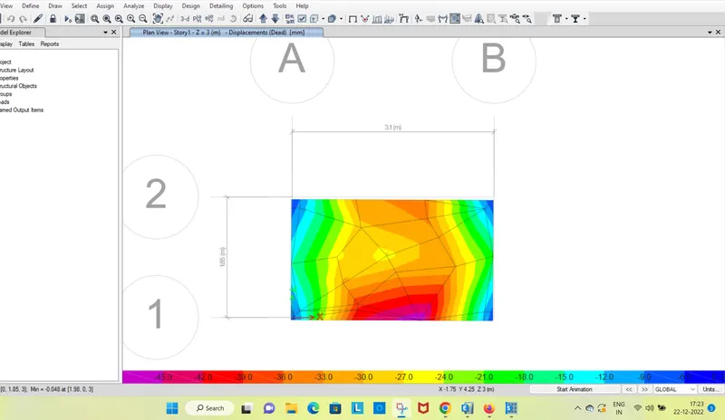
- now run the model
- click on run analysis
- we found that dispalcement is less than allowable settlement
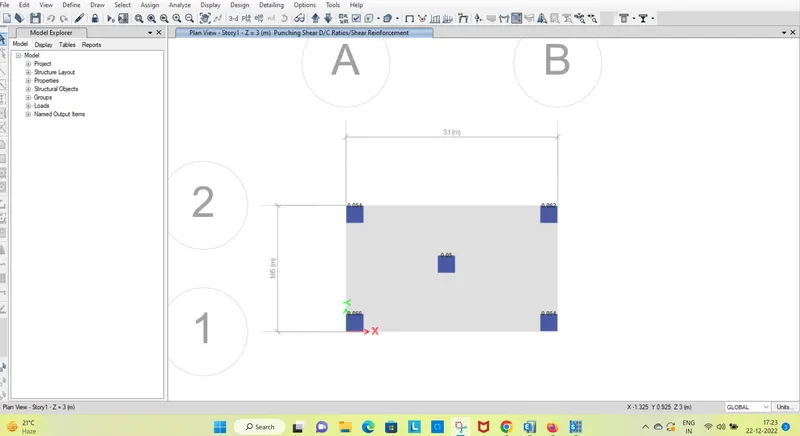
step 15 cheak for punching shear
joint reaction
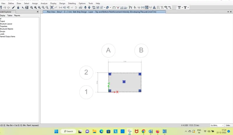
results
- pile cap designed for square column of size 600mm*600mm
- we have to provide pile cap size as 3.1*1.85m
- bearing soil pressure is cheaked and found to be safe
- punching shear ration is cheak and found to be safe .