Foundation Design using SAFE
AIM: the main aim of this challenge is to design isolated footing which is designed manually in previous challenge using safe software.
INTRODUCTION:
we have the following data which is designed in challenge 11 is shown below,
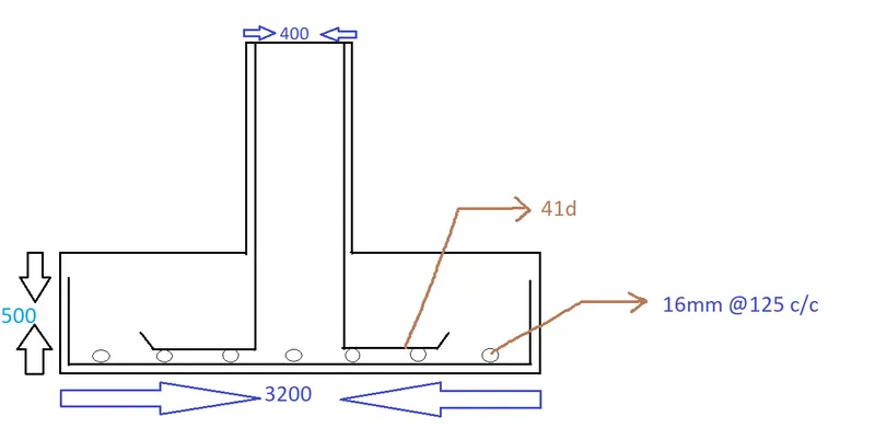
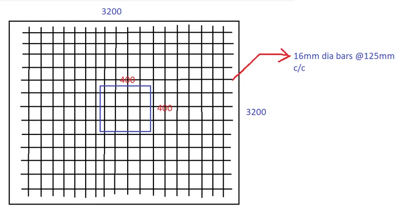
- square footing for a column size of 400mm*400mm
- compression axial load for the load combination of (1.5DL +1.5 LL) is 2000 KN
- safe soil bearing capacity is 150 KN/m^2 at a depth of 2m from E.G.L
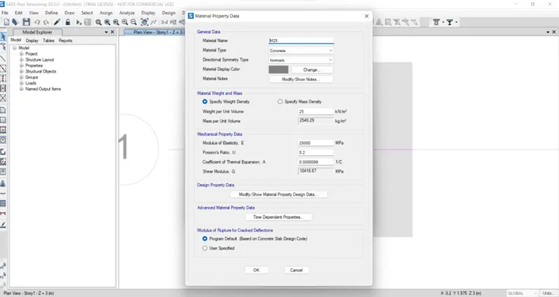
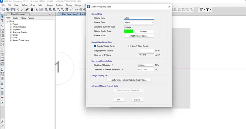
- assuming M25 grade concrete, fe500 grade steel
- unfactored load =2000/1.5=1333.3KN
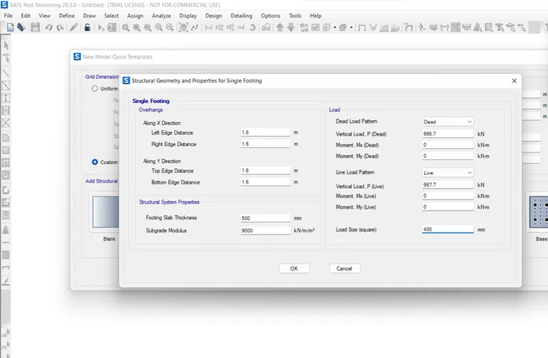
- dead load breakup=1333.3/2=666.7 KN
- live load breakup= 1333.3/2= 666.7 KN
- subgrade modulus for soil = (SBC*FOS)/Max. settlement= (150*3)/0.05= 9000 KN/m^3
- rebar yielding strength (fy)= 500 N/mm^2
- rebar ultimate strength (fu) = say 545 N/mm^2
- elastic modulus of M25 concrete =5000*square root of Fck= 5000*square root of 25=25000 N/mm^2
PROCEDURE:
- starting with the safe software and with the new model
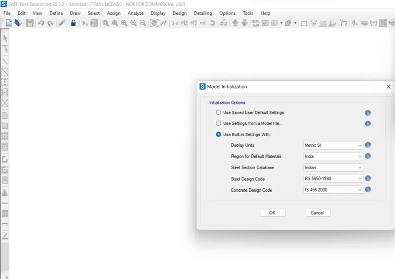
- entering into the model with model initialization settings as built in
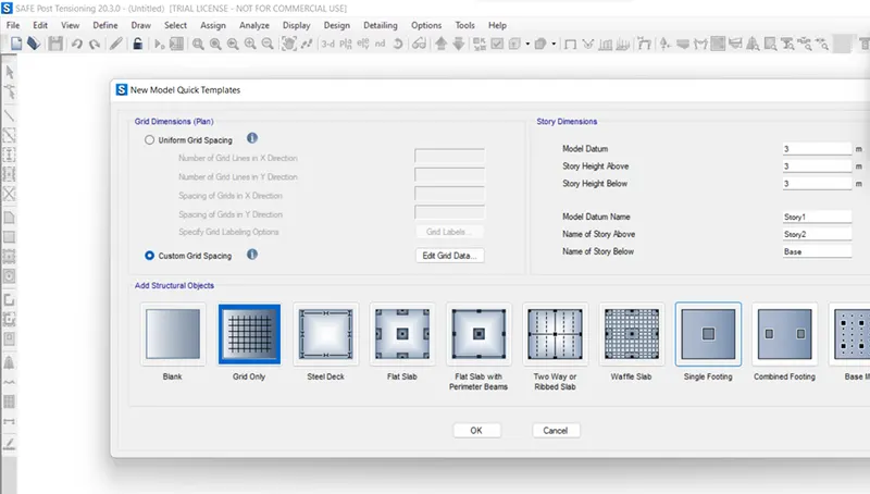
- taking the single isolated footing quick template as shown below
- giving the input details for single footing as shown below
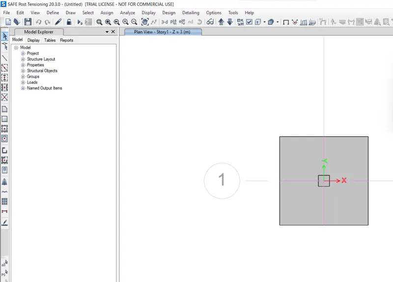
- quick template for isolated footing is as follows
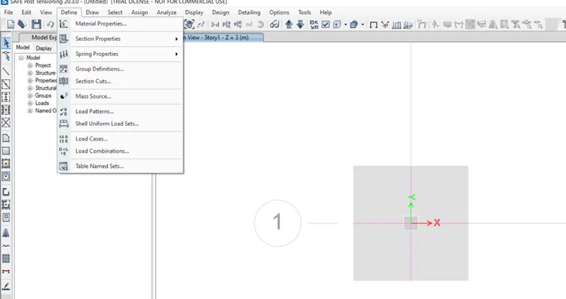
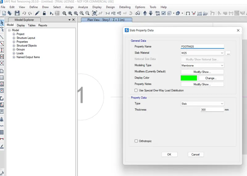
- defining the material properties such as M25 grade concrete, fe500 steel grade and slab properties such as footings, column as shown below
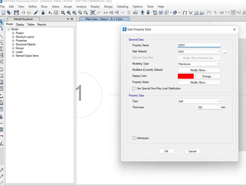
- defining the loads such as dead, live and soil surcharge as shown below
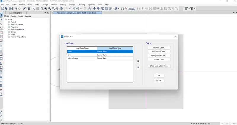
- assigning the soil sub grade for the footing slab
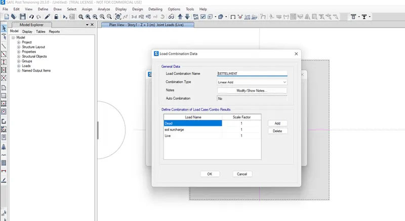
- defining the load combination for servicibility and ultimate load as shown below
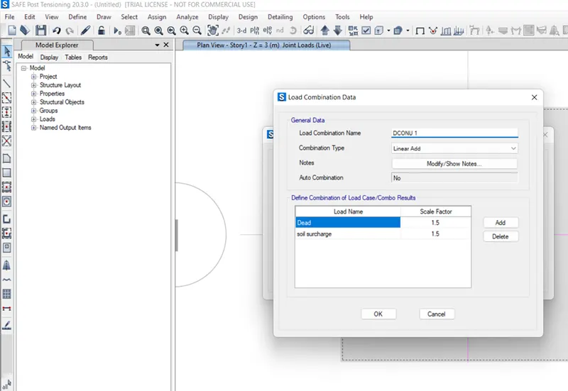
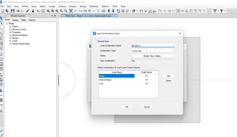
- drawing the design strips as shown below
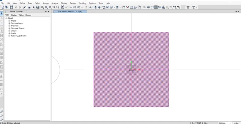
- checking the model for analysis
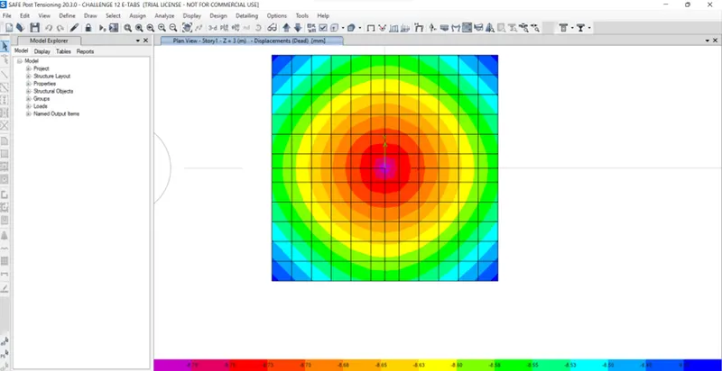
- if check passed, the model is gonna run for analysis
RESULT:
the following results are verified after analysis
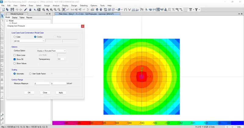
1.safe bearing capacity under service load : the reslts are under 150 KN/m^2, so it's okay.
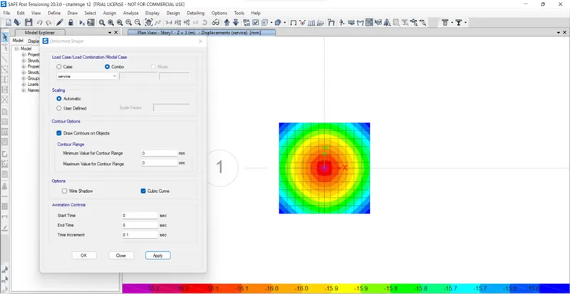
2.settlement under service load: the deformation is also safe and with in the limits as shown below
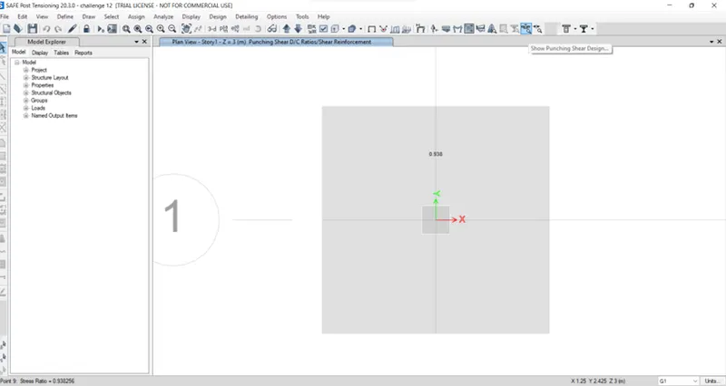
3.two way shear check (punching shear ): it is also with in the limit, so it's okay.
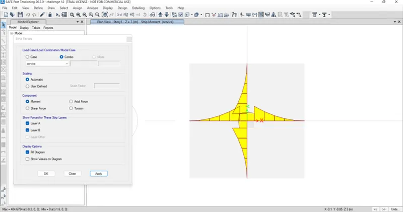
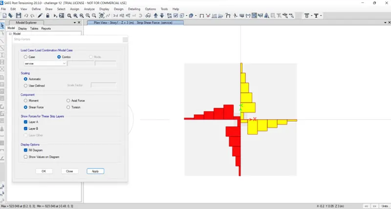
4. ultimate bending moment: the bending moment and shear force is shown below
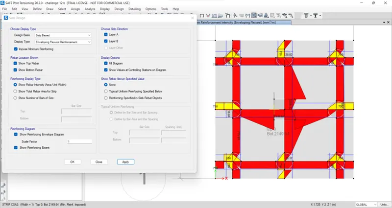
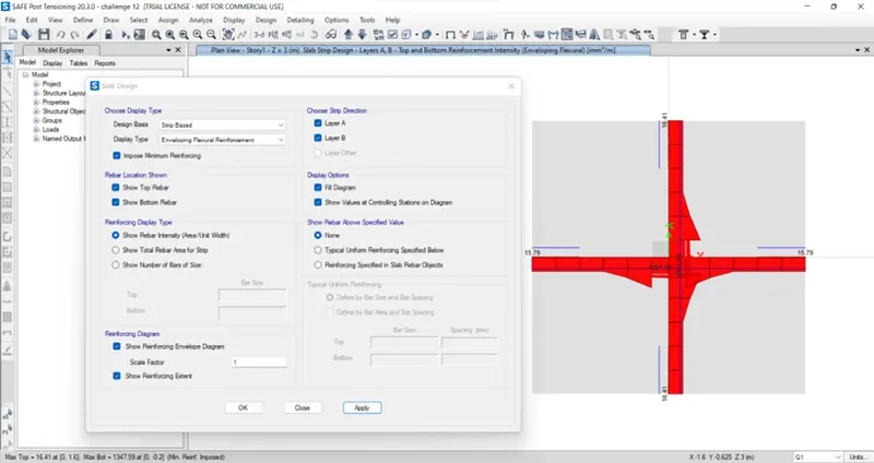
5.flexural reinforcement design for footing slab: the reinforcement details are shown below
2)
AIM: the main aim of the challenge is to make the design of pile footing using safe software
INTRODUCTION:
we have the following data for pile footing
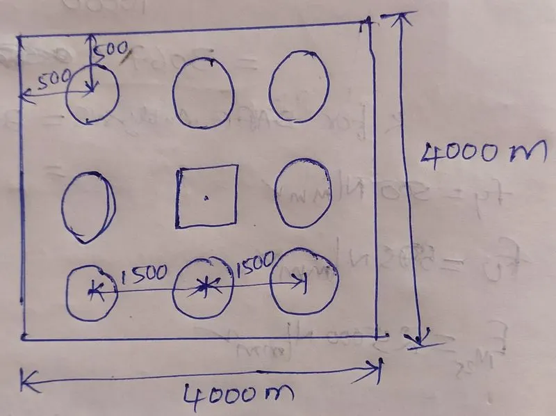
- A column of size 600x600 carrying an unfactored gravity load (DL+LL) of 1175 KN is to be supported on pile cap, which ultimately transfers load to the piles underneath. Piles of 16 metres length and 500 mm diameter are to be used. Each pile has a load carrying capacity of 200 KN.
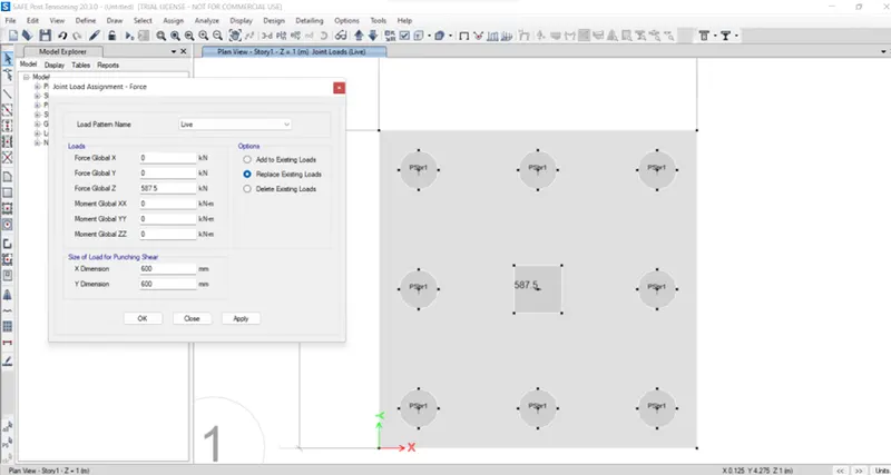
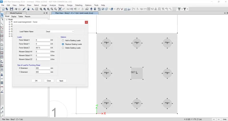
- dead and live loads are taking equally i.e 587.5 KN
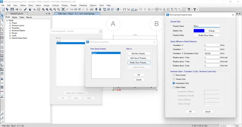
- in the pile foundation, point springs are used i.e point spring of pile = AE/L= (196349*25000)/16000=306796 N/mm= 306796 KN/m
- rebar yeilding strength (fy) = 500 N/mm^2
- rebar ultimate strength (fu) = 545 N/mm^2
- elastic modulus of M25 concrete = 25000 N/mm^2
- no of piles required = unfactored load with self weight addition/individual pile capacity= (1175*1.1)/200=6.5
we will consider 8 piles for symmetric placement of piles under pile cap
- taking center to center distance between piles = 3*pile diameter = 3*500 = 1500mm
- edge distance from pile center = 1*pile diameter=1*500=500mm
- assume pile cap depth as 500mm
PROCEDURE:
- starting with the safe software and with new model having model initialization settings as builtin as shown below
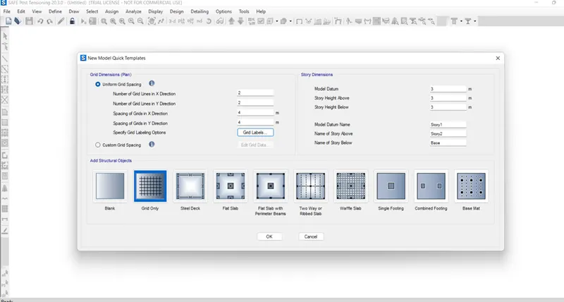
- using the new model quick templates, the footing is done with the given inputs as shown below
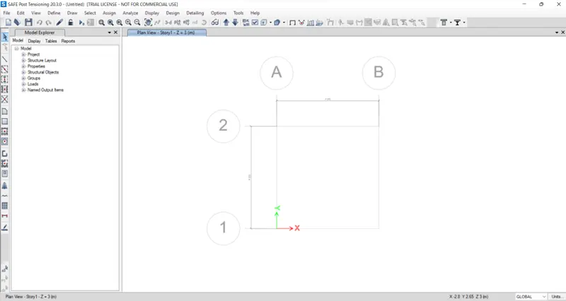
defining the materials such as M25 grade concrete, fe500 grade steel and slab sections such as pile-cap, column, pile-500 as shown below
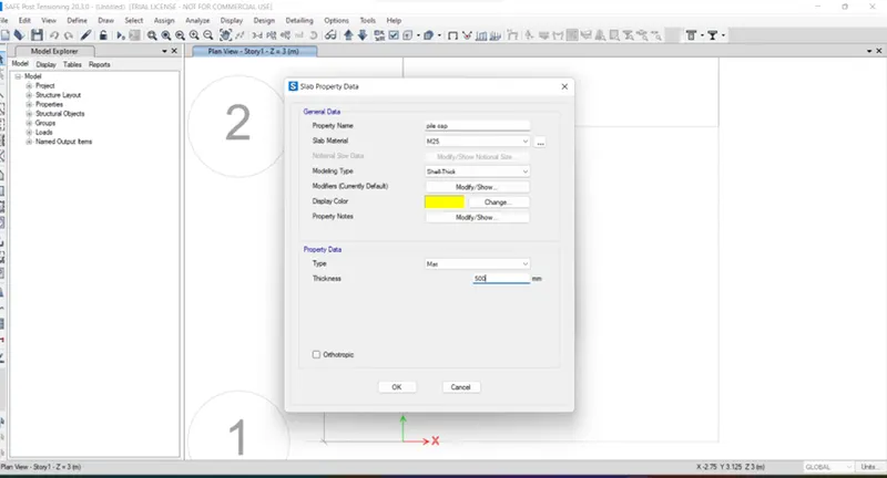
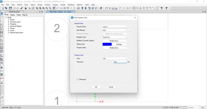
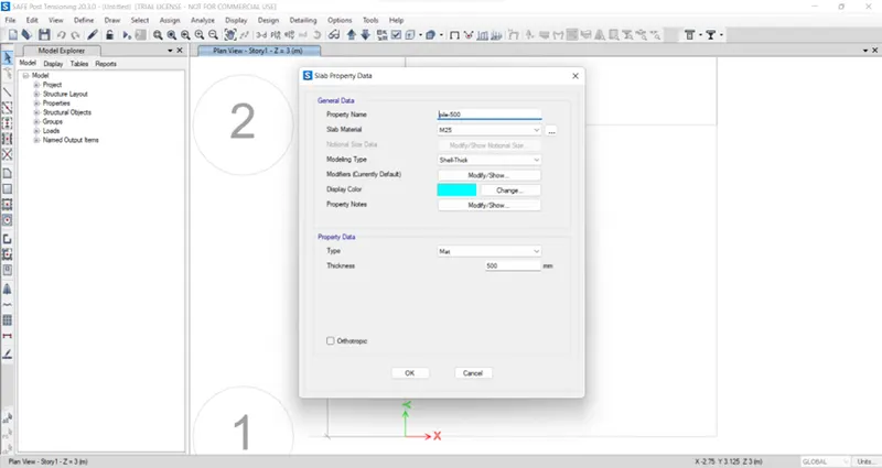
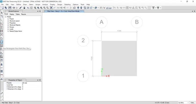
- using the option called draw floor/plan, the pile-cap is drawn as shown below
- using draw joint objects, the points are drawn for reference to draw pile-500 and column as shown below
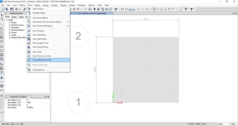
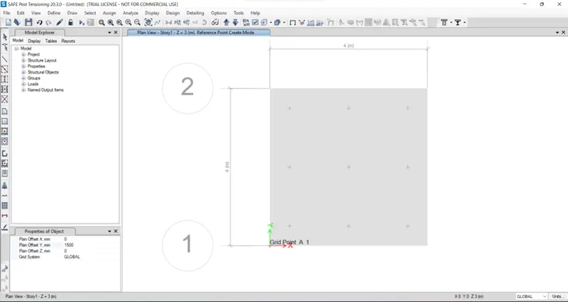
- using option draw area about points, the pile-500 and column is drawn as shown below
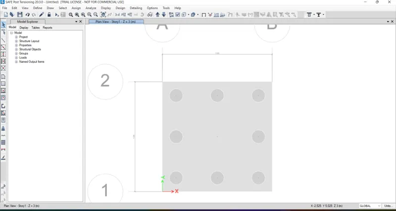
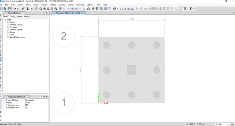
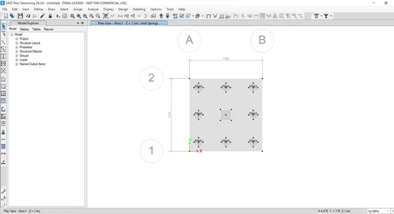
- using pile-500 joints, the point springs are assigned as shown below
- at the column joint, the dead and live load is assigned as shown below
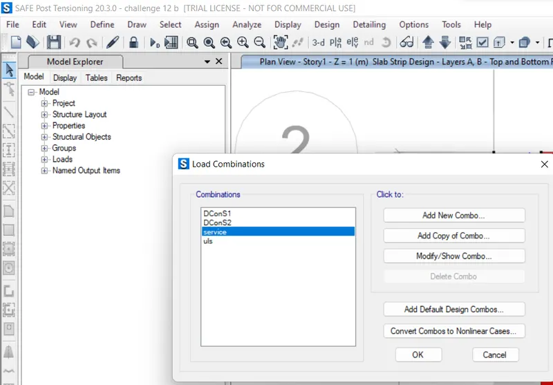
- also defining the load combinations for servicibility and iltimate limit. the design strips are also provided as shown below
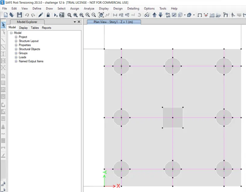
- finally the model is checked for analysis, if check is completed without any warnings.then, the model is gonna run for analysis
RESULT:
after the analysis, the following results are verified
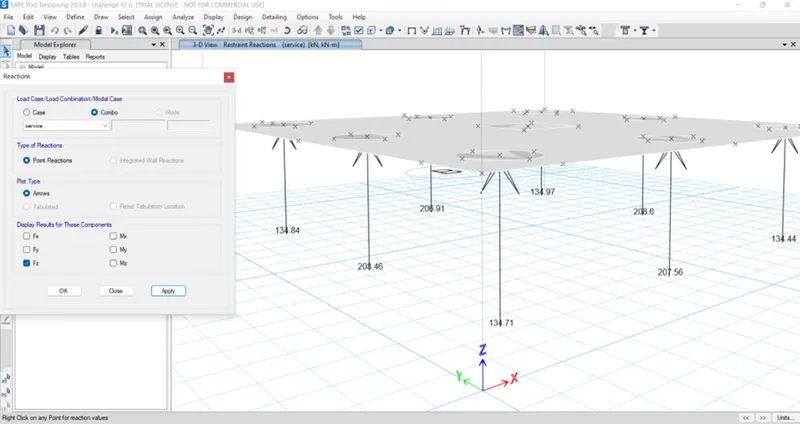
1.individual pile capacity: it's also safe shown below
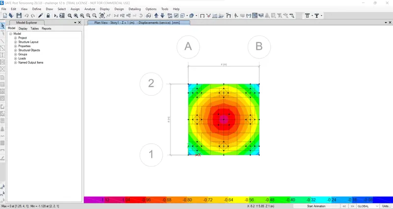
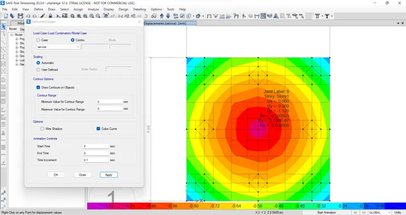
2.settlement under service loads: it's aslo safe
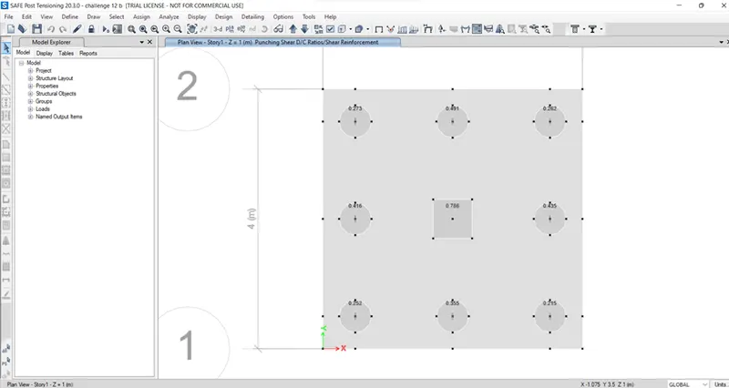
3. two way shear check: its also safe as shown below
4. flexural reinforcement design for footing slab: the reinforcement details are shown below