Foundation Design using SAFE
1. ANS,
AIM :
-
Model the isolated footing provided in week 11 challenge on SAFE. Analyze and design it to verify the size, depth and steel provided as per calculations.
INTRODUCTION :
- Draw the model of Isolated footing and check the desire requirement with use of CSI Safe software.
- Open the Safe software and open new on file then change the setting of Code as IS 456 - 2000
- Make it as metric command and add grid lines of the footing model
PROCEDURE :
- Draw a Footing of size 4 * 4 and depth of 600 mm
- Draw Column of size 0.40 *0.40
- Before draw the column and footing Define the material like ( Concrete M25 , Rebar FE500)
- Define Slab propety add column 0.40*0.40 and Footing 4 *4 with depth 600 mm
- Edit --- Design strips and draw the strips in horizontal and vertical to cross the column.
- Assign point load to the column center 587.5 Kn Dead and Live load.
- Define load combination SLS and Ultimate load combination.
- Once all done then run the analysis.
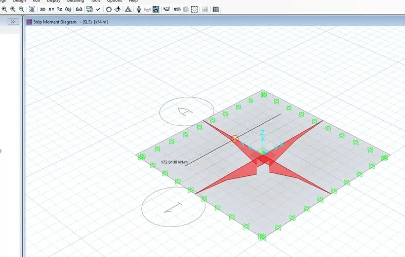
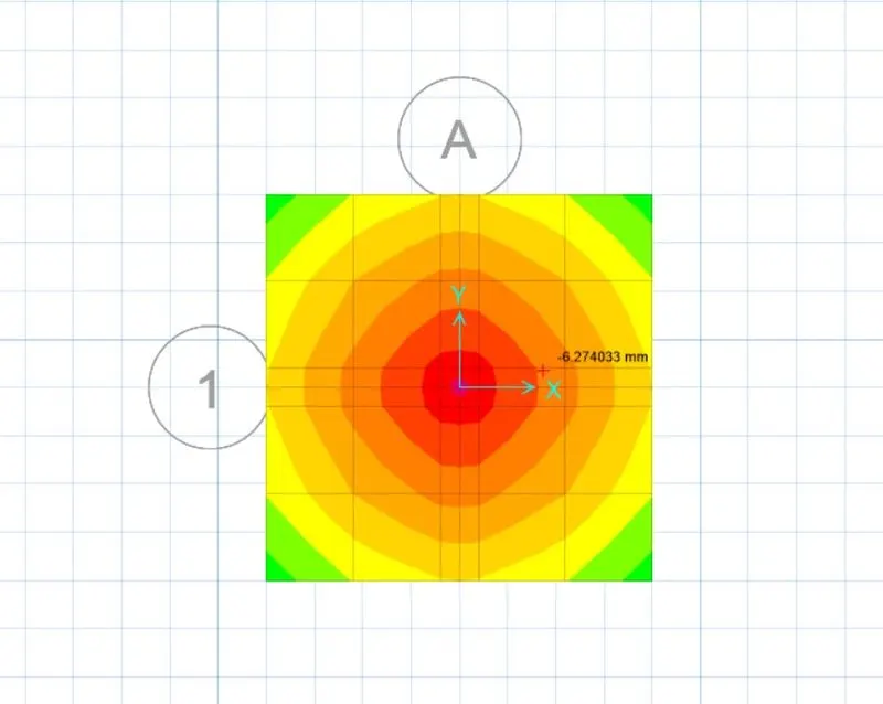
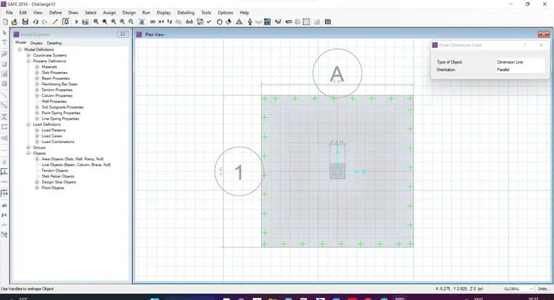
RESULT :
- As per the result of the design model the footing Deformation , punching shear and String desing all details under safe to execute the Model.
2, Ans,
AIM :
-
A column of size 600x600 carrying an unfactored gravity load (DL+LL) of 1175 KN is to be supported on pile cap, which ultimately transfers load to the piles underneath. Piles of 16 metres length and 500 mm diameter are to be used. Each pile has a load carrying capacity of 200 KN. Model, analyse and design the pile cap on SAFE to evaluate the following:
- Pile group to be used
- Depth of pile cap
- Longitudinal steel on top and bottom face in both directions
Note: Participants must refer to IS 2911 (part 2) and SP 34 for 2nd challenge
INTRODUCTION :
- To draw the pile foundation some of the datas are required and the datas are given below,
- Column = 600 mm * 600 mm
- Pile lenght = 16 m
- Pile dia = 500 mm
- Load at pile = 200 kn
- Spring constant = E*A/L
- = 25000*3.142*250*250/16000= 306835 n/mm = 306.835 kn/mm
PROCEDURE :
- Draw the pile cap of size 3.5 * 3.5.
- Before start to draw Define the material and Slab defination ( column, pile and pile cap) with the given details.
- Define column = 500 * 500 with depth 600 mm, pile under mat = 600 mm and pile cap = footing = 600 mm.
- Draw Pile and column using draw points option in DRAW menu and offset in both X and Y direction.
- Then Draw Pile and column using Quick draw acess around points.
- Assign load spring load on Pile from ASSIGN -- support load -- spring load and enter the value Spring constant trozonal load = 306.835 kn/mm.
- Assign point load to column with 587.5 kn/m.
- Load combination of Ultimat load of 1.5 Dead load + 1.5 Live load .
- EDIT --- Draw string --- along the pile center to center with end of the pile cab in both X and Y direction.
- Once check the Design as per IS 456 - 2000 and other values as per code and Run the analysis F5.
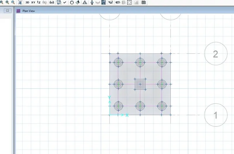
RESULT :
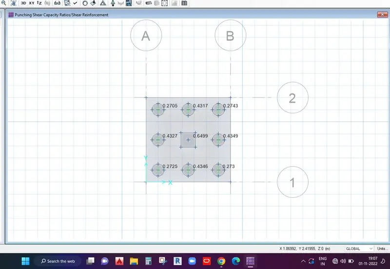
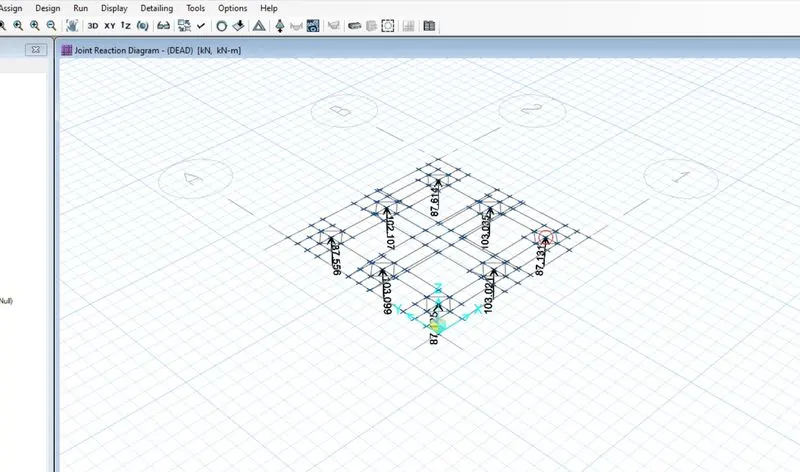
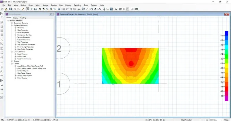
- From the above run the model is run successfull and the result for the pile and isolated footing is executed and the Displacement , punching shear , strip design and Reaction under safe, Hence Proved.