Foundation Design using SAFE
Foundation Design using SAFE
1. Model the isolated footing provided in week 11 challenge on SAFE. Analyze and design it to verify the size, depth and steel provided as per calculations.
Aim
To model and analyse the isolated footing on SAFE and also verify the size, depth and reinforcement provided
Procedure in Detail
1. Open Safe--> New Model---> Modify the Design Codes, Units and Design Preference as required.
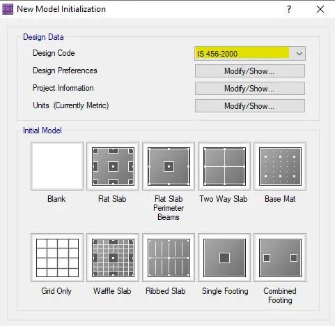
Designed as per IS standards therefore IS456:2000
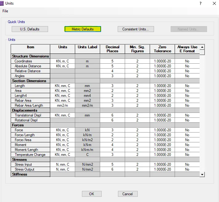
Choose Metric Units
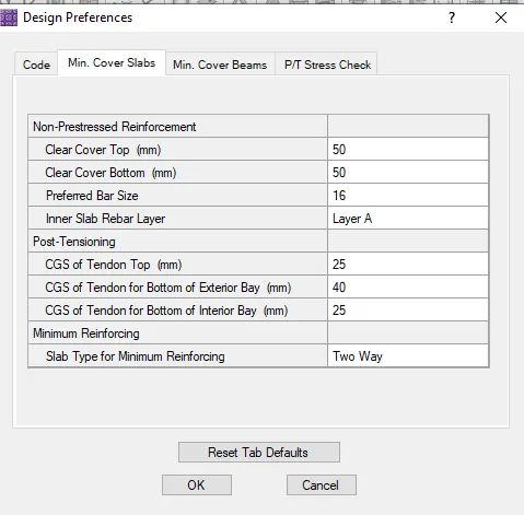
Preferred the reinforcment bar size and cover of footing
Select Single footing and give the details as required
Based on Challenge 12 the axial compression load on column as 2000kN
Safe bearing capacity of soil as 150 kN/m^2
The settlement of footing as 50mm
The unfactored load = 2000/1.5=1333.33kN
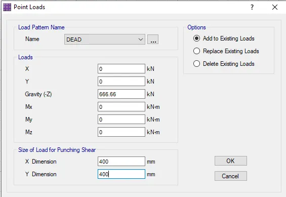
As the Dead and live load were given separately, therefore DL = LL= 666.66kN
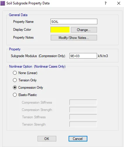
Subgrade Modulus = F.O.S x S.B.C/ permissible settlement
= ( 3 x 150)/0.050= 9000kN/m^3
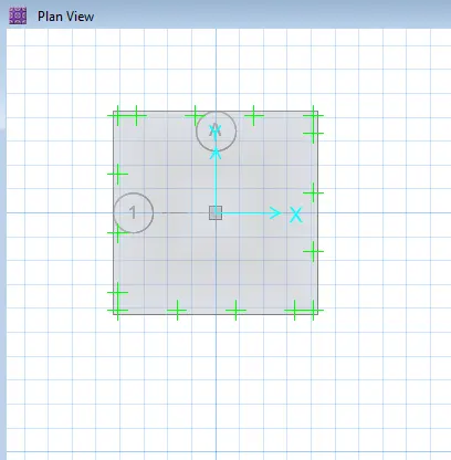
Once the value were given to single footing template and apply ok we we get the model as shown below
2. Material Define
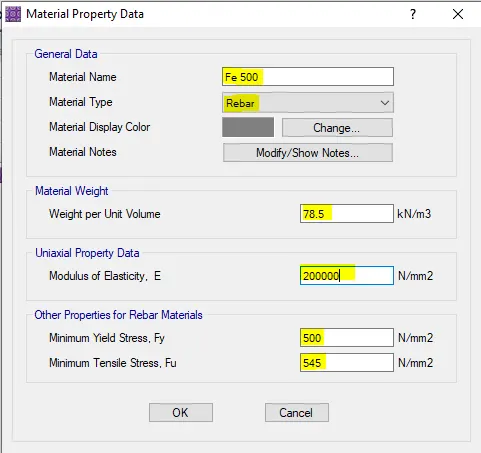
Go to Define->Material-->Add New property-->give the requirements
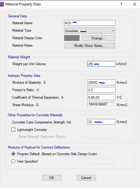
Similarly for rebar give the values as required
3. Define Frame properties
For footing the properties were designed as slab
go to define-->As we already define the size and shapes therefore cross check the value.
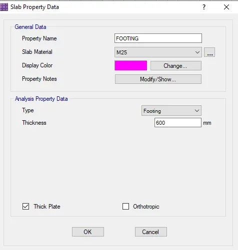
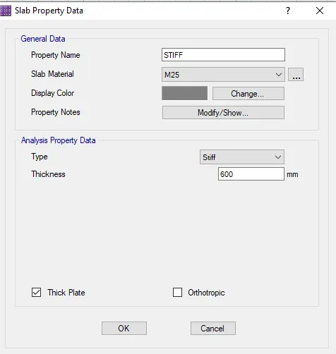
Similarily for Define Soil Subgrade properties
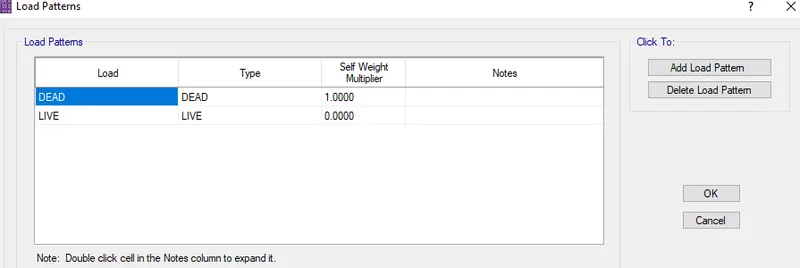
4. Define Load Pattern
5. Assign Loads
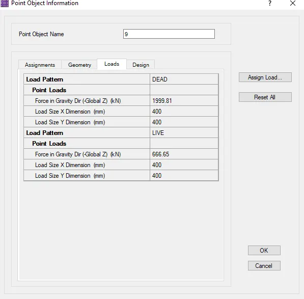
Loads are assigned as point load. Select the column point--> Go to assign --> Load Data---> Point Loads--> Give the parameters
6.Define Load Combinations
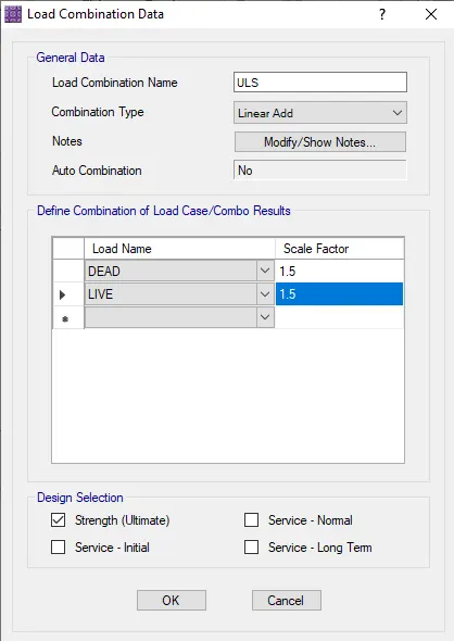
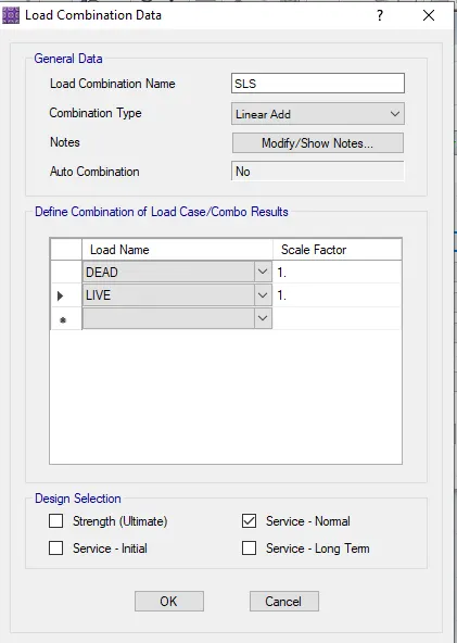
Two Load Combinations were defined
ULS for strength and SLS for serviceability
7.Check design preference
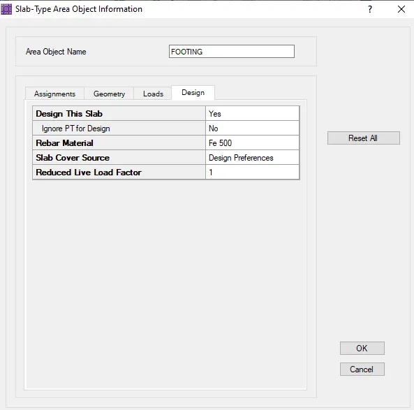
Check the design preference the reinforcement as Fe 500 and minimum cover for footing as 50mm
8. Analysis
Once analyze the structure displacement and soil pressure to be check with the soil report
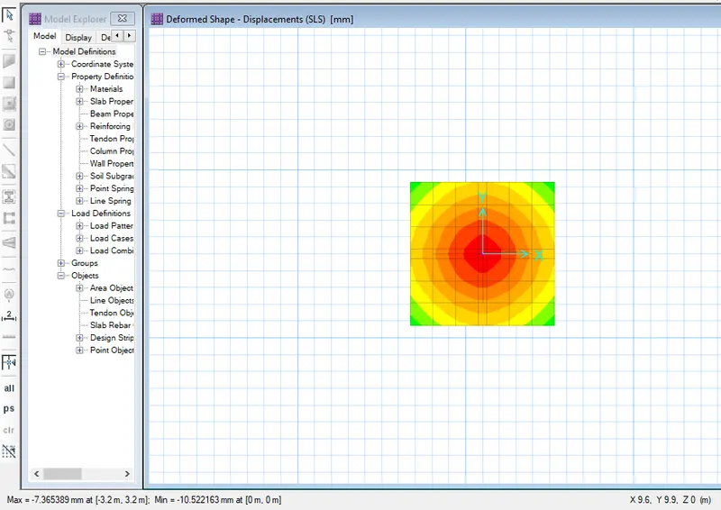
Displacement with maximum of 7.362mm which under the limit there fore satisied
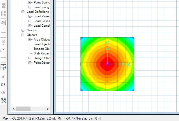
The maximum soil pressure of 66.29 and min 99kN/m^2. therefore it satisifies
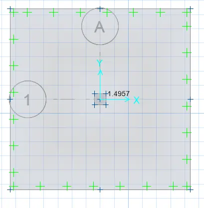
The punching shear value as 1.4 therefore we need to increase the depth of the footing.( As per standards punching shear should be less than 1
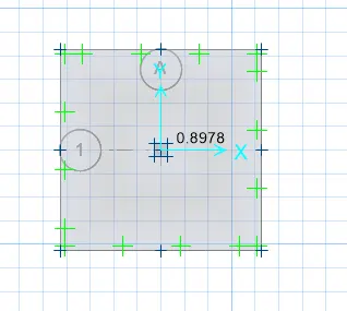
by Increasing the depth of footing we getthe value of 0.84, therefore it safisfies the limit
9. Design for reinforcement
Select the Object--> Edit-->Add Design Strips Layer A--> Auto -->
Run analysis again
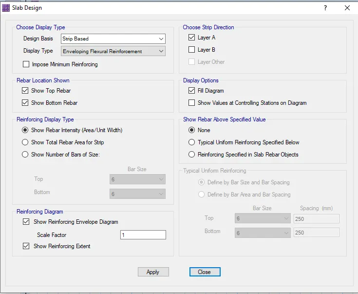
Go to Display--> show Slab Design-->Choose Strip Direction
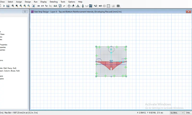
Similarly for the other layer B
Results
Thus the given isolated footing were analysed and and designed using safe software and verified with IS standard requirements
2. A column of size 600x600 carrying an unfactored gravity load (DL+LL) of 1175 KN is to be supported on pile cap, which ultimately transfers load to the piles underneath. Piles of 16 metres length and 500 mm diameter are to be used. Each pile has a load carrying capacity of 200 KN. Model, analyse and design the pile cap on SAFE to evaluate the following:
- Pile group to be used
- Depth of pile cap
- Longitudinal steel on top and bottom face in both directions
Aim
To model and analyse and design the pile cap footing using Safe and evaluate the depth and reinforcement of the foundation.
Procedure in Detail
The given parameters were
Column size 600 x 600 mm
Unfactored Load = 1175 kN
Length of the Pile 16m
Pile Diameter 500mm
Pile Capacity 200kN
Solution
Number of piles required 1175/200= 5.875 therefore 6 nos
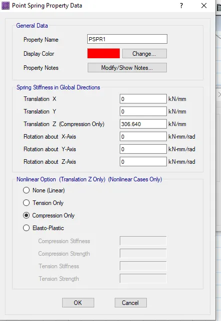
Spring Constant = EA/L
E--> young modulus of concrete
As per IS 456 E for M25 grade concrete is 5000.√fckf.ck=25000N/mm^2
A--> Cross sectional area of pile 0.785 x 500^2 = 196250mm^2
Pile length --> 16000mm
Substitute the value we get spring constant as 306640N/mm
Once the grid dimensions and Material properties given then provide the slab properties
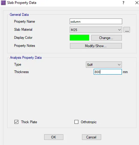
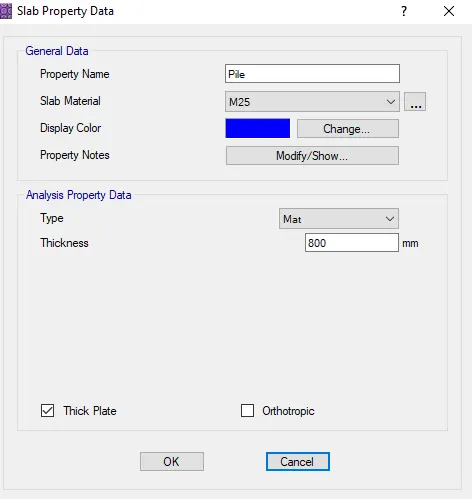
Here for Pile Foundation total three properties to be given i.e pile cap, pile and colum stiff
1. Define Pile Cap
Go to Define--> Slab Properties--> Add New
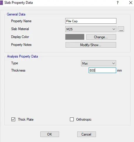
2. Define Column
3. Define Pile
4. Draw model of slab using Quick draw tools
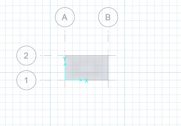
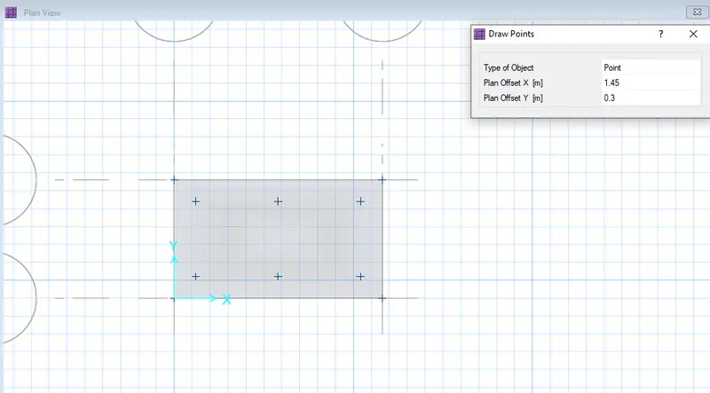
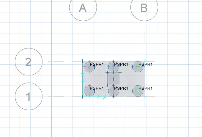
To draw piles first add points
Go to Drawpoints--> Dialog box open at top right corner--> Give the type of object as point and then provide the coordinate point
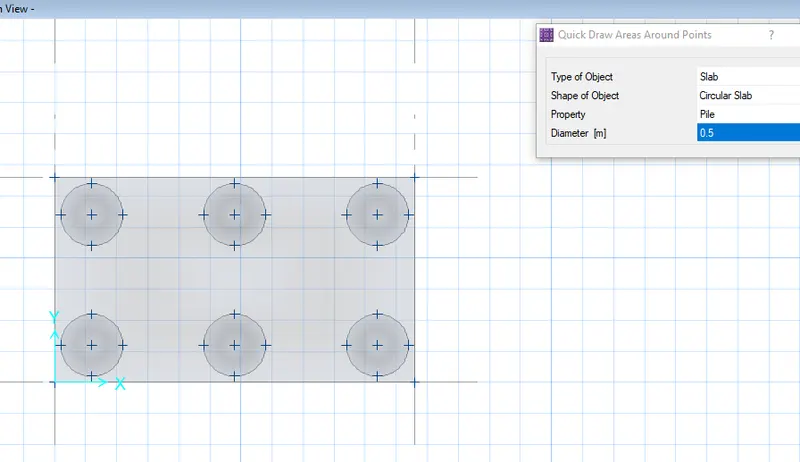
Add piles to the points we marked
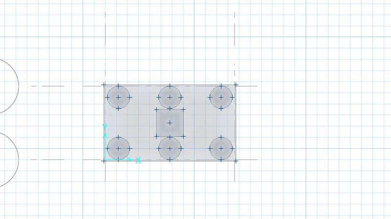
Create Columns of size 600x 600 mm Draw column in center using coordinates
5. Assign Spring to Piles
Assign-->Support Data-->Point Springs
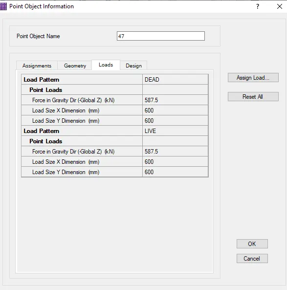
6.Assign Load and Load Combination
7. Analysis
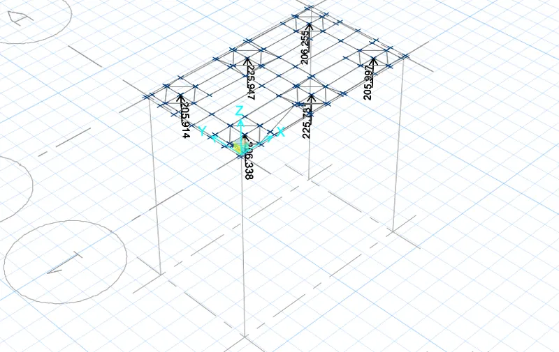
Once the load and load combination were design then run analysis and check the displacement and punching shear
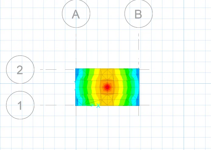
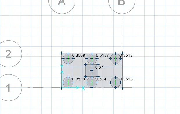
Point Reaction
All the above parameters are within the limit therefore satisfies.
Design reinforcement Details
Once the analysis were completed then design the model by design strip
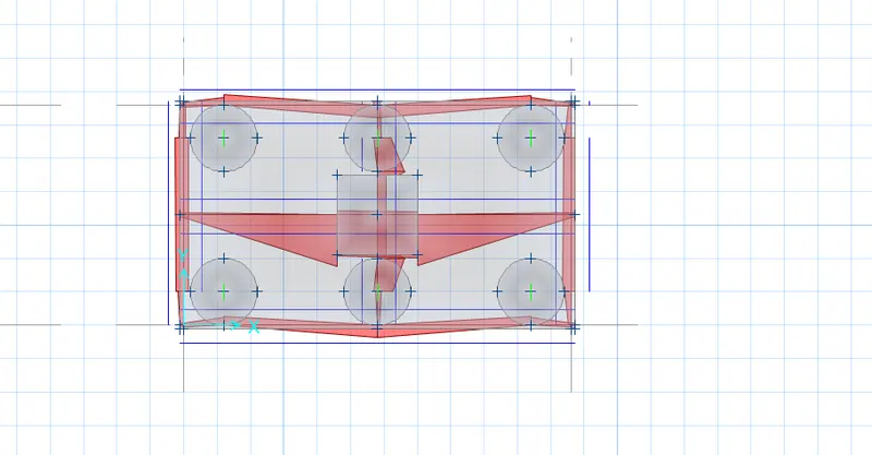
Results
Thus the Pile cap were designed using SAFE were done and verified