FINAL TEST
Questions based on PFI Engine:
1. What is the Compression ratio for the engine?
Compression ratio is the ratio of the maximum volume of the cylinder when the piston is at the bottom dead center to the minimum volume of the cylinder when the piston is at TDC.
From the below graph Vmax and Vmin values were found out.
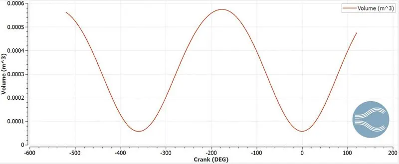
`V_c`= Clearance volume and `V_s`= Swept volume.
Compression ratio= `V_max/V_min`= `(V_c+V_s)/V_c=(0.000574)/(5.723e-5)`= 10.02.
2. Modify the compression ratio for this engine to 10.3 without changing geometrical parameters.
The compression ratio can be changed by changing the Swept/displacement volume or by changing the clearance volume.
We have, original `V_s= V_max-V_min= 0.000574-0.00005723= 0.000517m^3`.
Compression ratio= `(V_c+V_s)/V_c` and for given compression ratio= 10.3.
The new swept volume= `V_s=10.3V_c-V_c=10.3*0.00005723-0.00005723=0.000532m^3`.
and the new clearance volume for compression ratio= 10.3 is `V_c=V_s/(10.3-1)=0.0000556 m^3`.
3. Calculate Volumetric Efficiency for this engine.
Volumetric efficiency is the ratio between the actual (measured) volume of intake air drawn into the cylinder/engine and the theoretical volume of the engine/cylinder during the intake engine cycle.
`V_s=V_max-V_min=0.000574-0.00005723=0.000517 m^3`.
`eta_v=V_a/V_s`.
`eta_v=m_a/(rho_aV_s`. We know that the ideal gas equation is,
`P_aV_a=m_aRT_o` where `V_a=(m_aRT_o)/P_a`.
`P_a=101325 pa ,R=287J/(kgK),T_o=303K`.
`Va= 0.0004432 m^3`.
`eta_v=V_a/V_s=0.0004432/0.000517=0.857=85.7%`.
4. Measure the air mass flow rate for this engine in kg/s.
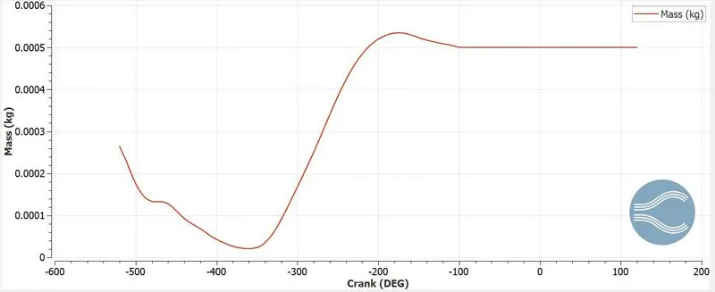
Mass of air from the above graph, ma= 0.0005344 kg.
Speed(N)= 3000 rpm= 3000/60 rps= 50 revolution/sec.
Mass flow rate `m_a`= (`m_axxN`)= `0.0005344xx50=0.0267 (kg)/s`
5. Why is the cell count varying during the simulation?
Cell count is varying due to the use of Adaptive Mesh Refinement(AMR) and Fixed embedding that has been provided. The velocity and temperature AMR is provided which basically captures the gradient of temperature and velocity and accordingly refines the mesh. Also, the fixed embedding is provided to the injector and spark plug which refines the mesh around that. So the cell count varies.
6. In a real engine, valves are in contact with the cylinder head but while running simulation, there is a small gap. Why?
In a real engine, there is no gap between valves and cylinder head. The portion is completely sealed. So that heat is not escaped through the gap. The heat is only dissipated through the cylinder head and cylinder walls. Valve spring and other components are required to keep the valves and cylinder head in contact. But in the case of simulation valve spring and other components are not designed, so a gap is provided instead of that. If the gap becomes big there will be less dissipation of heat from the cylinder causing an increase in temperature inside the cylinder. This will lead to knocking and NOx emissions.
7. How many seconds does combustion last in this case?
Speed= 3000 rpm= 3000/60 rps= 50 revolution/sec= 360*50 degree/sec
Combustion time= 240.199 degree
Combustion time in seconds= 240.199/(360*50)= 0.0133 s.
Questions based on DIESEL Engine:
1. What is an advantage of SECTOR Simulation?
Basically, in sector simulation, we take a sector of the cylinder rather than the full engine cylinder for simulation. Here we perform a closed cycle simulation. This reduces the computational time to a great extent. As we are taking a sector of the combustion chamber number of cells is less. Thus computational time is reduced drastically.
2. When will the sector approach not work?
The sector simulation will not work if we are performing an open cycle analysis. The valves timing needs to be considered in an open cycle analysis. Also in the closed cycle, the injectors are symmetric about the center of the engine. So a closed cycle analysis can be performed but not in the case of the open cycle.
3. How to choose Start Crank Angle (SCA) and End Crank Angle (ECA) for a sector simulation?
As we know that sector simulation holds good for closed cycle simulations, the engine is simulated for 360 degrees only. So the beginning of compression stroke can be the start and the end of expansion stroke can be the end of the simulation.
4. Can we convert the PFI case into a SECTOR case? Explain your answer?
The PFI engine is an open cycle analysis. A sector approach is only possible for closed cycle analysis. In a closed cycle simulation the engine is simulated for 360 deg. The position of injectors in the PFI case may not be symmetrical to consider sector simulation and also spark plug modeling also needs to be considered in the PFI engine. So it is not a good idea to simulate a PFI engine using a sector approach.