Final Project: Electric Rickshaw modelling
Aim:- Create a detailed MATLAB model of an electric rickshaw (three wheel passenger vehicle) as per details below:
Objectives:-
Rear wheels driven by PM brushed type motor
Assume efficiency points of motor controller and motor
Make an excel sheet of all input and assumed data
Results: For any three standard driving cycles show energy consumption, temperature rise of motor and controller for 100 km constant speed driving at 45 kmph.
Introduction:-
ELECTRIC RICKSHAW:-
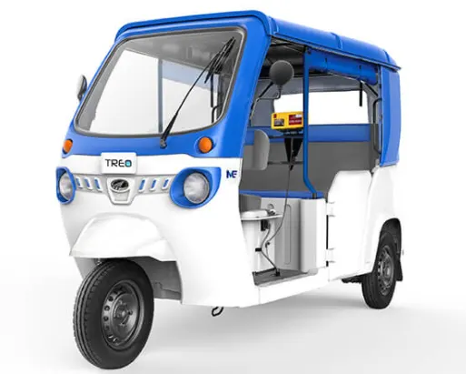
Mahindra Treo is a revolutionary new range of electric autos, e-rickshaw and cargo version. Powered by the advanced Lithium-ion technology, Mahindra Treo offers higher savings, superior ride quality and best in-class interior space. Ride the change with Mahindra Treo for a better tomorrow!
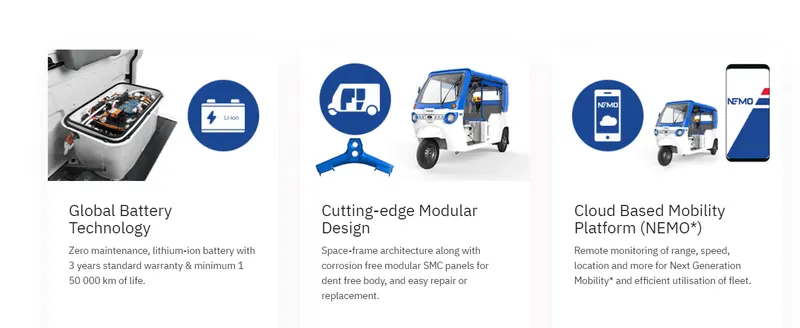
Key Highlights of Treo Zor:
Delivers Impressive Performance:
- Best-in-industry power of 8kW and Best-in-segment torque of 42Nm
- Boost Mode: Boost your driving experience with higher speeds and get quick turnaround times
- Advanced IP67-rated motor offers enhanced protection against dust & water entry
- Best-in-segment payload of 550 kgs - Get higher earning opportunities with the highest-in-class payload among electric 3 wheelers
- Get more trips per day with a certified driving range of 125 km
Safe & Stable like never before:
- Enjoy a safe & stable ride with longest-in-industry wheelbase of 2216 mm, when compared with diesel & electric cargo 3 wheelers
- Tread over potholes with ease with largest-in-industry tyres of 30.48 cm, when compared with diesel & electric cargo 3 wheelers
Advanced Lithium-ion Battery:
- Get a maintenance-free ride with battery life exceeding 1.50 lakh km
- Ease of charging: Charging your Treo Zor is as easy as charging a mobile phone. Just plug it into a 15AMP socket!
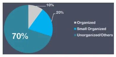
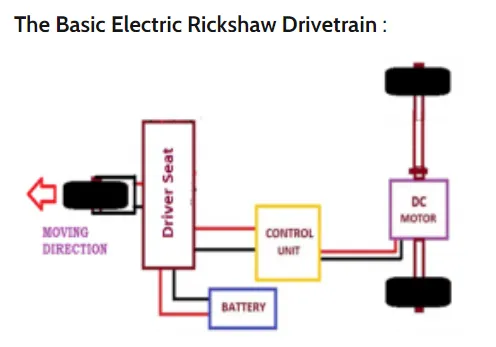
Electric rickshaws are becoming popular these days because of their low fuel cost, and less human effort compared to pulled rickshaws. They are being widely accepted as an alternative to petrol/diesel/CNG auto rickshaws. They are three-wheelers powered by an electric motor ranging from 650-1400 Watts. They are mostly manufactured in India and China. Battery run rickshaws could be a low emitter complementary transport for the low income people, who suffer most from a lack of transport facility, if introduced in a systematic manner. E-Rickshaw's have now transitioned from being a market entrant in the automobile segment of the country to evolve as a leading short distance transport solution. The share of production for e-rickshaws for now is indicated below.
Battery-run rickshaws could be a low-emitter complementary transport for the low-income people, who suffer most from a lack of transport facility, if introduced in a systematic manner according to experts.
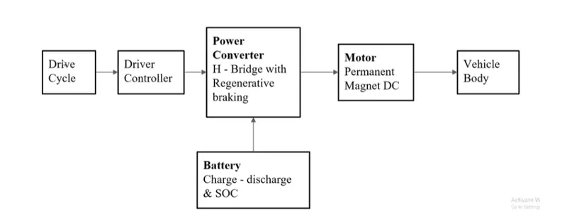
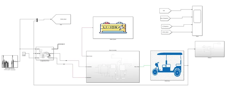
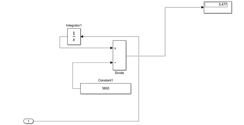
In the designed Electric Rickshaw main blocks are Battery, drive cycle, controller, DC Motor, Vehicle body & Transmission system. Drive cycle is the input data like how a human drive his actual vehicle here FTP75, WOT & Excel (Manually Prepared in Excel sheet) drive cycles are used to make the designed vehicle to give the output how it reacts to the drive cycle. The main objective is to obtain the speed by the driver, to estimate the temperature of Motor and Controller, to estimate the sates of charge (SOC), distance travelled by the vehicle. There is a SOC block that will estimate the state of charge of a battery, distance is calculated by speed and time parameters for all the three Drive cycles.
Electric Rickshaw Model:-
Modelling of Vehicle Body System:-
Part 1:- Vehicle body
The Subsystem consists of different blocks namely
- 3 tires
- Vehicle body
- Inertia
- Simple Gear
The Subsystem is Shown below:-
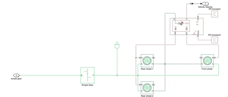
Note:-The above figure shows that when the Rear wheels 1 & 2 moves Automatically Front wheel also moves.
Tire:-
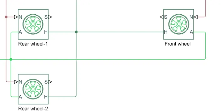
A- Axles [Mechanical rotational port associated with the axle that the tire sits on.]
S- Slip [Physical signal output port associated with the relative slip between the tire and road.]
H- Hub [Mechanical translational port associated with the wheel hub that transmits the thrust generated by the tire to the remainder of the vehicle.]
N- Normal force [Physical signal input port associated with the normal force acting on the tire. The normal force is positive if it acts downward on the tire, pressing it against the pavement.]
These tires are connected to the vehicle body.
The vehicle body has various inputs can be modulated for the vehicle to have a basic setup as it consists of parameters
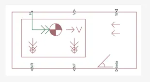
- NR - Normal Force Rear [Physical signal output port for normal force on the rear axle. Wheel forces are considered positive if acting downwards.]
- NF - Normal Force Front [Physical signal output port for normal force on the front axle. Wheel forces are considered positive if acting downwards.]
- H - Horizontal motion[Conserving port associated with the horizontal motion of the vehicle body. Connect tire traction motion to this port.]
- V - Longitudinal velocity,Speed of the vehicle body [Physical signal output port for vehicle longitudinal velocity.]
- Beta - Road incline angle,The grade of the vehicle.[Physical signal input port for road incline angle.]
INERTIA:-
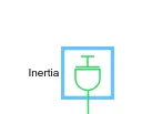
This block generally represents the mechanical rotational element.
`T=Jfrac{dw]{dt}`
Where,
T= Inertia torque
J = Inertia
Ω = Angular Velocity
T = Time
The inertia is connected to the simple gear to find the inertia because of axel and gear are a mechanical rotating devices.
SIMPLE GEAR
The Simple Gear block represents a gearbox that constrains the connected driveline axes of the base gear, B, and the follower gear F
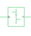
B: The output B,base gear is connected with the input of DC motor R. It is a Rotational mechanical conserving port.
F: The output of F,Follower gear is connected with rear axle.It is also a Rotational mechanical conserving port.
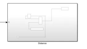
Distance Subsystem:-
To find distance of the vehicle a Subsystem is shown below
Battery System:-
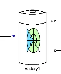
The Battery block represents a lithium-ion battery model.The Battery model is shown below.
The Battery subsystem shows below
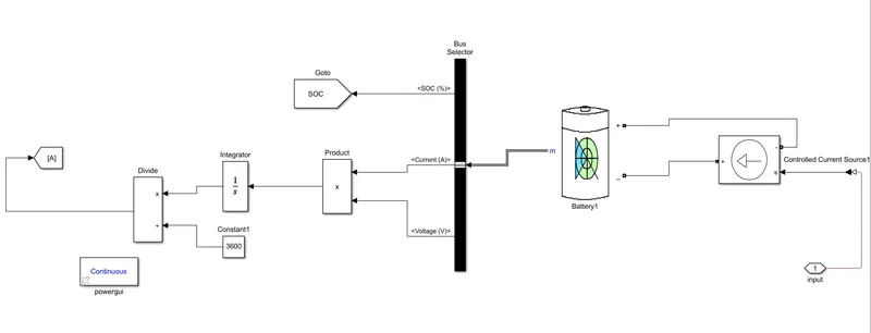
The Components used in Battery are
- Controlled Current Source
- Bus Selector (SOC,Current,Voltage)
- product
- integrator
- constant
- Divide
- Goto
- If we select Infinite for the Battery charge capacity parameter, the block models the battery as a series resistor and a constant voltage source.
- If we select Finite for the Battery charge capacity parameter, the block models the battery as a series resistor and a charge-dependent voltage source.
- In the finite case, the voltage is a function of charge and has the following formula is mentioned as
`V=V_o(frac{SOC}{1-beta(1-SOC)})`
Where
- SOC (state-of-charge) is the ratio of current charge to rated battery capacity.
- V0 is the voltage when the battery is fully charged at no load, as defined by the Nominal voltage, Vnom parameter.
- β is a constant that is calculated so that the battery voltage is V1 when the charge is AH1.
The connection of the battery is as follows,the negative(-)terminal is connected to the ground and then controls the current source physical port to the positive direction which indicates the flow of current.
The positive (+) terminal is connected to the controlled current source of electrical conserving ports.
Controlled Current Sensor:-
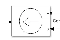
- The Controlled Current Source block represents an ideal current source that is powerful enough to maintain the required current through the voltage across the source
- In the controlled Current sensor,it has two-port connected to the battery and one electrical converting port is connected with the PS-Simulink converter to rate transition block and scope.
- The current sensor is a device that detects and converts current to get an output voltage, which is directly proportional to the current in the designed path.
- When current is passing through the circuit, a voltage drops across the path where the current is flowing. Also, a magnetic field is generated near the current-carrying conductor.
PS-Simulink Converter:-

- The PS-Simulink Converter says about connecting the physical signal to the simulink signal. We use this block in the system to connect mostly scopes like physical signals to the simulink signal or simulink scope.
- For Calculating the SOC we have to use Subsystems to connect different parameters like Rate transition,Gain block,Discrete Time Integrator,Constant and Sum block.
product Block:-
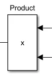
The Product block outputs the result of multiplying two inputs: two scalars, a scalar and a nonscalar, or two nonscalars that have the same dimensions. The default parameter values that specify this behavior are:
-
Multiplication:
Element-wise(.*) -
Number of inputs:
2
Powergui:-
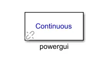
The powergui block allows you to choose one of these methods to solve your circuit:
-
Continuous, which uses a variable-step solver from Simulink®
-
Discretization of the electrical system for a solution at fixed time steps
-
Continuous or discrete phasor solution
The powergui block also opens tools for steady-state and simulation results analysis and for advanced parameter design.
You need the powergui block to simulate any Simulink model containing Simscape™ Electrical™ Specialized Power Systems blocks. It stores the equivalent Simulink circuit that represents the state-space equations of the model.
When using one powergui block in a model:
-
Place the powergui block in the top-level diagram for optimal performance.
-
Make sure that the block is named
powergui.
Motor and Controller System:-
The motor and Controller Subsystem is shown below
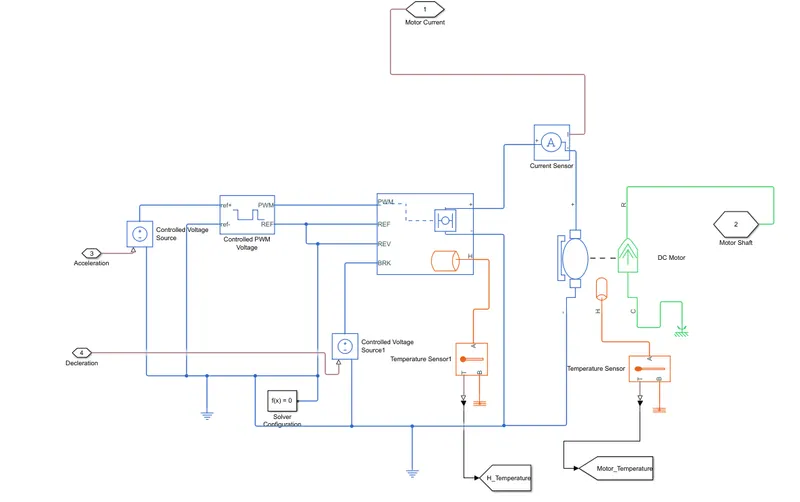
The Components Used in above figure are
- DC Motor
- Mechanical Reference
- Thermal port
- Temperature Sensor
- H-Bridge
- Current sensor
- Controlled Voltage source
- Controlled PWM Voltage
- Solver Configuration
- Electrical Reference
- Thermal Reference
- DC Motor:-
T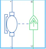
Parameters:-
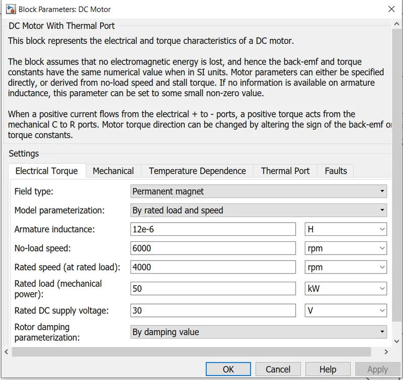
As we see in the above figure it mainly has 2 sides to the block.The Mechanical block is on the right and electrical block is on the left. Mechanical block has 2 ports ,C and R.The C refers to Casing and R refers to the rotor which produces a Torque.The electrical side has a positive and a negative terminal for the Voltages to be applied.If a positive voltage is Electrical conserving port associated with the DC motor.If a negative voltage is Electrical conserving port associated with the DC motor.
Here in this system ,the positive terminal is connected with the current sensor; the negative terminal is connected with the negative terminal of H-Bridge.
R is DC motor rotor which connects with mechanical rotational port where it is simple gear where as C is DC motor case it is connected to the mechanical rotational reference
Mechanical Reference:-
The mechanical reference block is shown below
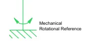
The Mechanical Rotational Reference block represents a reference point, or frame, for all mechanical rotational ports. All rotational ports that are rigidly clamped to the frame (ground) must be connected to a Mechanical Rotational Reference block.
Thermal port:-

It is used to regulate the temperature of the motor
Step 1:- press Right click on the DC Motor block r H-Bridge Block
Step 2:- now get the options and press simscape option
Step 3:- Now u will get no thermal port and Block Choices .press block choice and get the block
H-Bridge:-
The power converter is needed to provide power of the correct form and magnitude from one component to another.In EV’s a power converter is needed to provide a DC voltage from battery of the EV to DC motor.As mentioned i have used a type of H-Bridge motor drive as my power converter.The block is shown below
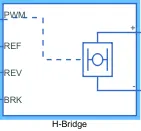
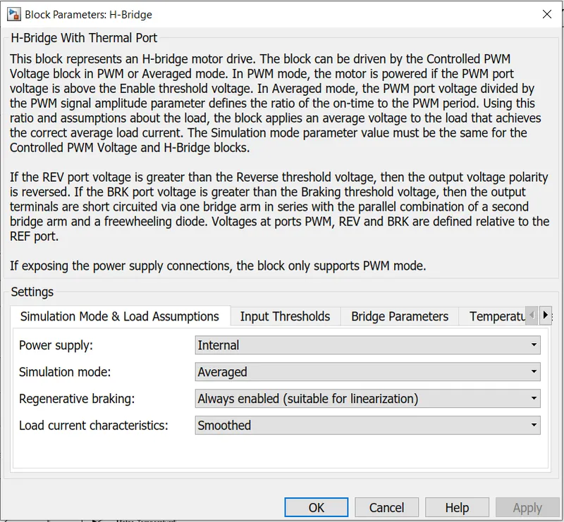
The H-bridge has 2 ports:-the left side is for controlling of voltage signals and the right side for the terminals to provide the controlled voltage of DC motor.The left side ports of the H-Bridge are shown below
- PWM:-This stands for Pulse Width Modulation which will provide the voltage pulses to the H-Bridge either in the PWM or average mode
- REF:-This stands for the Reference
- REV:-This stands for the Reverse
- BRK:-This stands for the Brake
Here PWM output port is connected with PWM input port of controlled PWM voltage.The REF and REV port are connected with REF port of controlled PWM voltage port.The BRK port is connected with a controlled voltage source.
It shows that the Positive terminal is connected to the positive terminal of the current sensor and negative terminal is connected with the negative terminal of the DC motor.
Controlled PWM Voltage:-
The Controlled PWM Voltage block represents a pulse-width modulated (PWM) voltage source. The block is shown below.

Ref+:-Positive electrical reference voltage.
Ref - :-Negative electrical reference voltage
PWM:-Electrical conserving port associated with the pulse-width modulated signal.
REF:-Electrical conserving port associated with the floating zero volt reference
For the Electrical input ports variant of the block, the demanded duty cycle is
`100*frac{V_(ref)-V_(min)}{V_(max)-V_(min)} percent`
where:
- Vref is the reference voltage across the ref+ and ref- ports.
- Vmin is the minimum reference voltage.
- Vmax is the maximum reference voltage.
The value of the Output voltage amplitude parameter determines amplitude of the output voltage.
Controlled Voltage Source:-
The Controlled Voltage Source block represents an ideal voltage source that is powerful enough to maintain the specified voltage at its output regardless of the current flowing through the source.The block is shown below
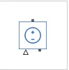
The output voltage is V = Vs, where Vs is the numerical value presented at the physical signal port.
The block has one physical signal input port and two electrical conserving ports associated with its electrical terminals.
Temperature Sensor:-

The Temperature Sensor block represents an ideal temperature sensor, that is, a device that determines the temperature differential measured between two points without drawing any heat.
Connections A and B are thermal conserving ports that connect to the two points where temperature is being monitored. Port T is a physical signal port that outputs the temperature differential value.
The block positive direction is from port A to port B. The measured temperature is determined as T = TA – TB.
Ports
The block has the following ports:
A-
Thermal conserving port associated with the sensor positive probe.
B-
Thermal conserving port associated with the sensor negative probe.
T-
Physical signal output port for temperature.
Solver Configuration:-
The Solver Configuration block specifies the solver parameters that your model needs before you can begin simulation.The Block is shown below.

The block has one conserving port. You can add this block anywhere on a physical network circuit by creating a branching point and connecting it to the only port of the Solver Configuration block.
It is connected with the controlled PWM voltage and for a model only one solver configuration is connected.
Electrical Reference:-
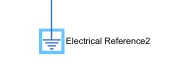
- The Electrical Reference block represents an electrical ground.As it shown below
- Electrical conserving ports of all the blocks that are directly connected to ground must be connected to an Electrical Reference block.
- A model with electrical elements must contain at least one Electrical Reference block.
- In this we had connected the electrical reference for the battery and motor etc..
Thermal Reference:-

The Thermal Reference block represents a thermal reference point, that is, a point with an absolute zero temperature, with respect to which all the temperatures in the system are determined.
Ports
The block has one thermal conserving port.
Longitudinal Driver:-
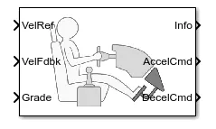
The Longitudinal Driver block implements a longitudinal speed-tracking controller. Based on reference and feedback velocities, the block generates normalized acceleration and braking commands that can vary from 0 through 1.
The different types are
- VelRef:-Reference velocity, vref, in m/s.
- VelFdbk:-Longitudinal vehicle velocity, U, in the vehicle-fixed frame, in m/s.
- Grade:-Road grade angle, θ or γ, in deg.
- Info:-Bus signal containing these block calculations.
- AccelCmd:-Commanded vehicle acceleration, yacc, normalized from 0 through 1.
- DecelCmd:-Commanded vehicle deceleration, ydec, normalized from 0 through 1.
The inputs parameters are given below:-
- Control Type:-PI is a Proportional-Integral (PI) Control with tracking windup and feed-forward gains.
- Reference and Feedback unit:- m/s
Discussing about Connection:-
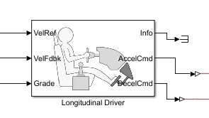
- VelRef:-Reference vehicle velocity is connected with speed result block.its units is m/s.
- VelFdbk:- Longitudinal vehicle velocity is connected with an integrator block for continuous-time integration of the VelFdbk signal.
- Grade:- Road grade angle is connected with constant block is 0
- Info:-Bus signal,Here we have used the signal to terminate the signal block.
- AccelCmd:-Commanded vehicle acceleration is connected with controlled voltage source input signal by combination with PS-Simulink Converter.
- DecelCmd:-Commanded vehicle deceleration is connected with another controlled voltage source signal by combination of PS-Simulink converter.
Drive Cycle Source:-
The Drive Cycle Source block generates a standard or user-specified longitudinal drive cycle.
In the model i have used FTP75 Drive Cycle Source.The drive cycle source is given below
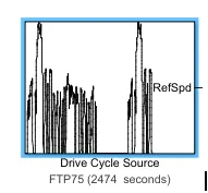
The output plotted the model for FTP75 Model is
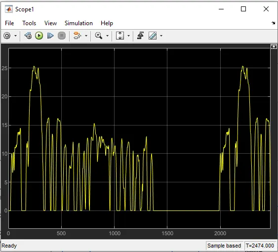
The connection drive cycle RefSpd is connected with the VelRef of Longitudinal driver and to the scoop results which generate vehicle reference speed.
The block output is the specified vehicle longitudinal speed, which we can use to:
- Predict the engine torque and fuel consumption that a vehicle requires to achieve desired speed and acceleration for a given gear shift reference.
- Produce realistic velocity and shift references for closed loop acceleration and braking commands for vehicle control and plant models.
- Study, tune, and optimize vehicle control, system performance, and system robustness over multiple drive cycles.
Results:-
For FTP75 Drive Cycle:-
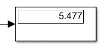
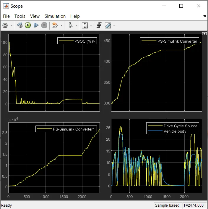
- The actual Speed is approximately followed the 90% of reference Drive cycle.
- SOC of the battery is reduced to = 0
- Motor Temperature is increased `≈450°c`
- Control Temperature is `2.5*10^4`
- vehicle body increases when we increase the rated load and decrease the Rated DC supply voltage
Conclusion:-
As per the Motor specification, Type of controller, Vehicle Parameters & Battery used we could see that the reference speed almost matches with the vehicle speed for the drive cycle FTP 75
The Parameters that can be changed / Improved:
- Detailed simulation rather than performing averaged mode simulation.
- Here I have compromised with the temperature of Motor and controller to achieve vehicle speed is near to reference speeds.Since I haven’t used any cooling system in the model. In the real time application, the motor temperature is less than 100
- Optimization of Battery pack for increased mileage and peak performance
- Optimization in the vehicle parameters such as vehicle mass, Front Area, Drag, Tire design etc
- Better Motor characteristics or Motor such as BLDC motor, which reduces the losses produced from brushes and better efficiency. Hence Better motor power and Torque can be achieved
- This Battery powered Rickshaw will be the most popular mode of transport in the future.