Final Project: Electric Rickshaw modelling
Create a detailed MATLAB model of an electric rickshaw (three wheel passenger vehicle) as per details below:
Rear wheels driven by PM brushed type motor
Assume efficiency points of motor controller and motor
Make an excel sheet of all input and assumed data
Results: For any three standard driving cycles show energy consumption, temperature rise of motor and controller for 100 km constant speed driving at 45 kmph.
Aim:
To Create a detailed MATLAB model of an Electric Rickshaw (three wheel passenger vehicle).
Software used:
MATLAB R2020a (Simulink)
Objectives:
- Rear wheels driven by PM brushed type motor
- Assume efficiency points of motor controller and motor
- Make an excel sheet of all input and assumed data
- Results: For any three standard driving cycles show energy consumption, temperature rise of motor and controller.
Block Diagram:
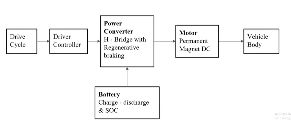
In the designed Electric Rickshaw main blocks are Battery, drive cycle, controller, DC Motor, Vehicle body & Transmission system. Drive cycle is the input data like how a human drive his actual vehicle here FTP75, WOT & FTP72 drive cycles are used to make the designed vehicle to give the output how it reacts to the drive cycle. The main objective is to obtain the speed by the driver, to estimate the temperature of Motor and Controller, to estimate the sates of charge (SOC), distance travelled by the vehicle. There is a SOC block that will estimate the state of charge of a battery, distance is calculated by speed and time parameters for all the three Drive cycles.
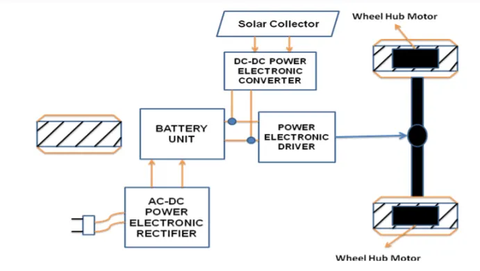
Drive train of the Electric Auto Rickshaw
Components
The main components of an EV are:
- Auxiliary Battery: In an electric drive vehicle, the auxiliary battery provides electricity to power vehicle accessories.
- Traction Battery Pack: Traction battery pack is also known as Electric Vehicle Battery (EVB) which is used to store the electricity. Some examples of traction battery energy storage systems are as given:
- Lithium-Ion
- Nickel-Metal Hydride
- Lead-Acid
- Ultra-Capacitors
- DC/DC Converter: Basically, DC/DC converter is an electronic device which is used to converts higher-voltage DC power from the traction battery pack to the lower-voltage DC power. The converted power is used to run the vehicle accessories. It is also used to recharge the auxiliary battery.
- Electric Traction Motor: Another important component is electric traction motor and this device is used to provide motive power to the wheels.
- Onboard charger: Takes the incoming AC electricity supplied via the charge port and converts it to DC power for charging the traction battery. It monitors battery characteristics such as voltage, current, temperature, and state of charge while charging the pack.
- Power electronics controller: This unit manages the flow of electrical energy delivered by the traction battery, controlling the speed of the electric traction motor and the torque it produces.
- Charge port: The charge port allows the vehicle to connect to an external power supply in order to charge the traction battery pack.
- Thermal system (cooling): This system maintains a proper operating temperature range of the electric motor, power electronics, and other components.
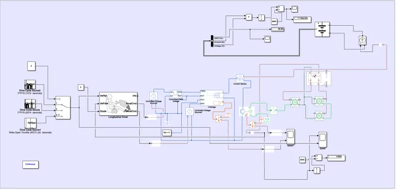
MATLAB Model of an Electric Rickshaw:
Model parameters:
Drive Cycle:
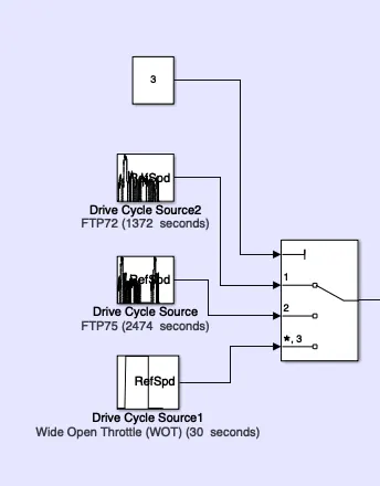
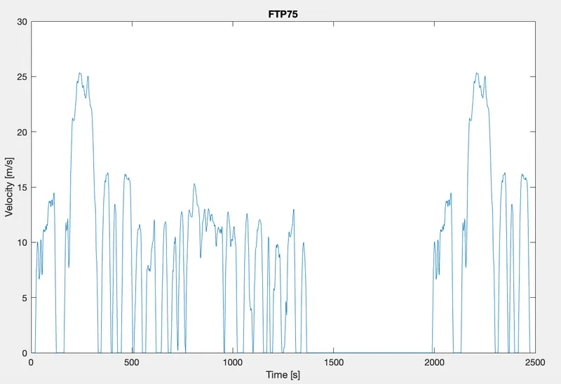
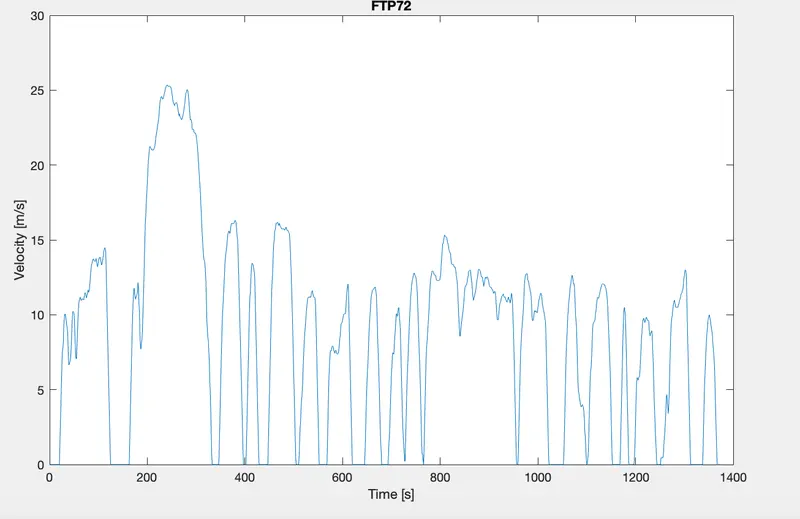
Drive cycle is assumed as the driver's input of a vehicle, it replaced how a driver will drive a vehicle. Here I have used three drive cycles which is used to test the vehicle performances. These drive cycle will have high speed, low speed, braking conditions in it. There are different drive cycles like WOT, FTP75 etc., Here in this model I have used FTP 75, WOT & FTP72
Generates a standard or user-specified longitudinal drive cycle. The block output is the vehicle longitudinal speed. You can import drive cycles from:
- Predefined sources
- Workspace variables, including arrays and time series objects
- mat, xls, xlsx, or txt files
Use the fault tracking parameters to identify drive cycle faults within specified speed and time tolerances.
FTP 75:
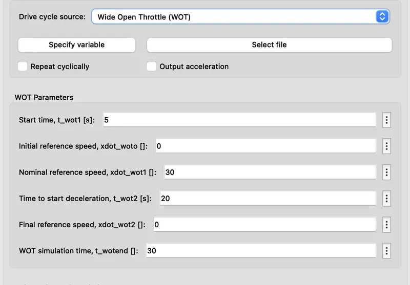
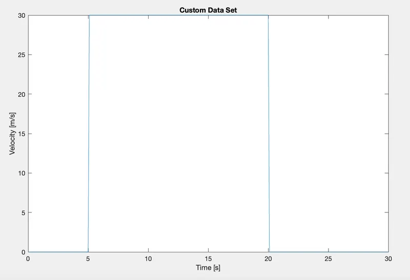
When the 'WOT' drive cycle is chosen, some extra parameters are made available for modification which are shown below:
FTP72:
All 3 Drive cycles are controlled by the controller provided above by constant through Multi-port switch.
Longitudinal Driver:
The longitudinal driver block is used for giving normalized acceleration and deceleration commands to a controller based on 2 sets of data. The first data set is the reference velocity and the second data set is the feedback velocity. The longitudinal driver block is shown below:
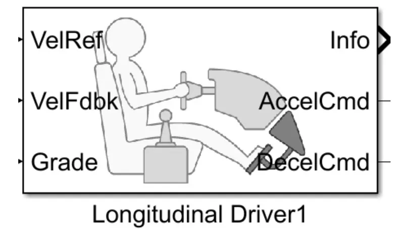
The longitudinal driver block has the following ports:
- VelRef - This stands for the reference velocity and it is the velocity data provided from a drive cycle source.
- VelFdbk - This stands for the feedback velocity and it is the velocity data provided from the vehicle body's velocity port which outputs the velocity data.
- Grade - This port provides a grade or inclination angle for the surface on which the vehicle is travelling in degrees.
- Info - This port is for the bus signals which consist of block calculations e.g. acceleration/deceleration command, difference between reference and vehicle speed.
- AccelCmd - This port provides the acceleration command to a controlled voltage source.
- DecelCmd - This port provides the deceleration command to another controlled voltage source.
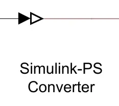
The working of the longitudinal driver block is simple. The reference velocity data coming from a drive cycle source is compared to the feedback velocity data coming from the vehicle body block. If the reference velocity is greater than the feedback velocity, an acceleration command will be given as an output to the controlled voltage source. If the reference velocity is lesser than the feedback velocity, a deceleration command is given as the output to another controlled voltage source instead. For the acceleration and deceleration commands to be given as output signals, I have used a Simulink - PS converter block. This block is needed whenever we wish to connect a Simulink input signal to a physical signal. In this case, the input signal is velocity data and this is logic data which we want to convert to a physical signal i.e.. voltages to the controlled voltage source.
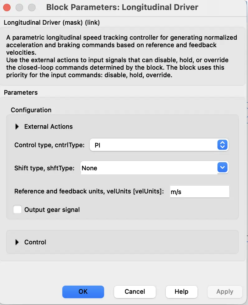
As we can see, I am using a PI controller for this block and I have set the reference and feedback velocities to be in m/s units. All the other parameters are unchanged.
The Simulink - PS converter block is shown below:
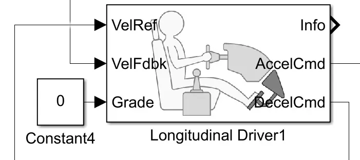
Grade
The grade port of the longitudinal driver block is connected to a constant block with a constant value of 0. This is so that no road inclination is modelled for the simulation. This can be seen in the image below:
Motor & Controller:
1. Motor type: DC Motor (PM brushed type motor)
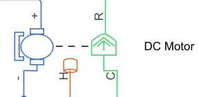
This block represents the electrical and torque characteristics of a DC motor includes Thermal port to sence the temperature of Motor.
The block assumes that no electromagnetic energy is lost, and hence the back-emf and torque constants have the same numerical value when in SI units. Motor parameters can either be specified directly, or derived from no-load speed and stall torque. If no information is available on armature inductance, this parameter can be set to some small non-zero value.
When a positive current flow from the electrical + to - ports, a positive torque acts from the mechanical C to R ports. Motor torque direction can be changed by altering the sign of the back-emf or torque constants. Motor Parameters:

the thermal here we took has 20000j/k because as the motor runs it generates heat the thermal mass should be greater it is above the mass it may cause the thermal runaway causes the damage to the entitr system so assume it has the greater value.
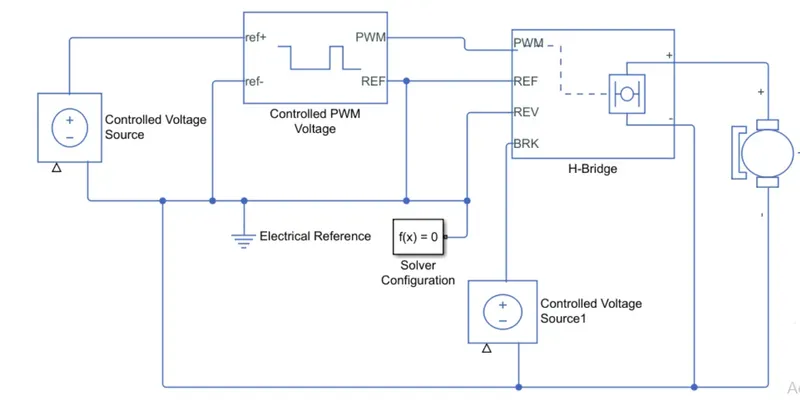
TheMotor controller will get input from the longitudinal driver. Its tasks are to control the speed of the motor and drive according to the input of the driver. Majorly motor controlled we designed had two main parts named PWM voltage generator and H-Bridge.
Input1 is getting from the accelmd of a longitudinal driver and it is given to a controlled voltage source block where it is input to the controlled PWM voltage. Controlled PWM voltage will generate a PWM signal in such a way that H-bridge will generate the required voltage to operate the DC motor for the given driver input. PWM voltage block negative reference and REF are grounded and REF of H-bridge respectively. H-bridge is a motor controller that has IGBT components aligned in the shape of H and will operate only two at a time respectively to the input of the signal from the PWM block. When deceleration occur this H-bridge will give an output from the positive and negative terminals of it. These negative & positive terminals are later connected to the DC motor and battery. All these components are the simscape electrical components so they need a connection to the solver configuration block which helps to solve the simulation.
2. Controlled PWM Voltage source:
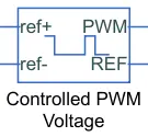
This block creates a Pulse-Width Modulated (PWM) voltage across the PWM and REF ports. The output voltage is zero when the pulse is low, and is equal to the Output voltage amplitude parameter when high. Duty cycle is set by the input value. Right-click the block and select Simscape->Block choices to switch between electrical +ref/-ref ports and PS input u to specify the input value.
At time zero, the pulse is initialized as high unless the duty cycle is set to zero or the Pulse delay time is greater than zero.
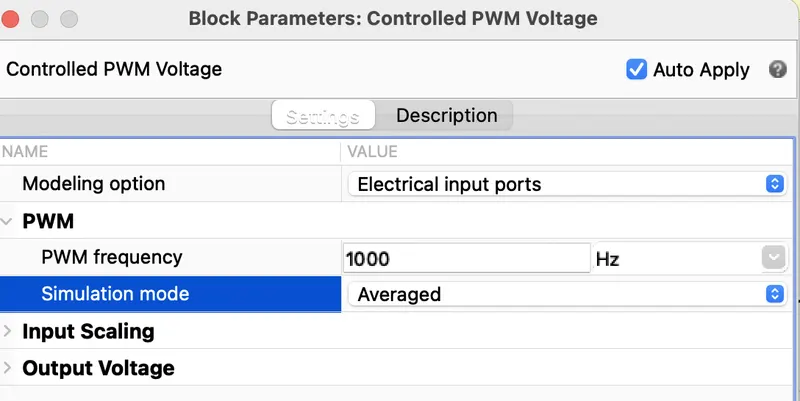
The Simulation mode can be set to PWM or Averaged. In PWM mode, the output is a PWM signal. In Averaged mode, the output is constant with value equal to the averaged PWM signal.
Select Simulation mode as Averaged.
Controlled Voltage Source
The input ports of the controlled PWM voltage block are still unconnected and that is because they require a controlled voltage source to provide the voltages to produce the voltage pulses to be fed in to the H-Bridge. For this, I have used the controlled voltage source block. This block is useful because it will provide the necessary voltage that is powerful enough to maintain the voltage at the output regardless of the current that passes through it. This controlled voltage source block is shown below:
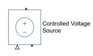
In this model, 2 controlled voltage sources have been used. One block is to provide the voltage for the acceleration of the vehicle and the other is to provide the voltage for the deceleration of the vehicle.
Electrical Reference
The electrical reference block is used to create a grounding effect for electrical circuits. Any model that uses electrical or electronics components will need to have at least one electrical reference block in it. The electrical reference block is shown below:
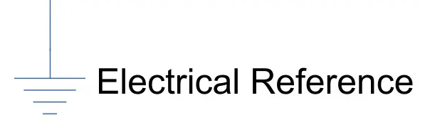
In my EV model, we are using this block for 2 occasions. The first is for to create an electrical ground between the controlled voltage source, controlled PWM voltage and the H-Bridge blocks. The second is for the battery system which will be modelled afterwards.
Solver Configuration
The solver configuration block is used to solve any necessary equations in a model and in my case, I have used them in the connection to the 'REV' port of the H-Bridge block. The solver configuration block is shown below:
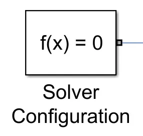
The image below shows the connections that can be made with the components discussed till this point.
3. Power Converter:
H-Bridge:
H-Bridge is used as a DC-DC converter.
The power converter is needed to provide power of the correct form and magnitude from one component to another. In the case of EVs, a power converter is needed to provide a DC voltage from the battery of the EV to the DC motor so that it can operate properly with the required parameters. As mentioned earlier, I have used an H-Bridge motor drive as my power converter. Its block is shown below:
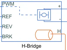
The H Bridge has 2 sides to it: the left side is for the controlling of the voltage signals and the right side is for the terminals to provide the controlled voltage to the DC motor. The left side ports of the H-Bridge block are:
- PWM - This stands for Pulse Width Modulation which will provide the voltage pulses to the H-Bridge either in the PWM or average mode.
- REF - This stands for Reference.
- REV - This stands for Reverse.
- BRK - This stands for Brake.
- orange line represents the temperature by using temperature sensor.
Opening the H-Bridge block will take us to its parameters shown below:
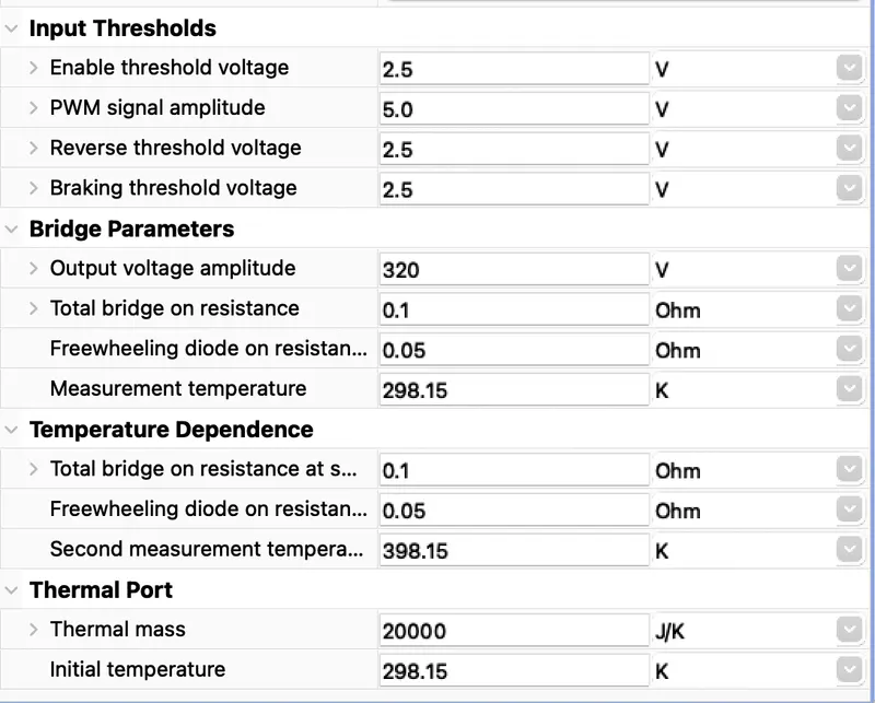
The main parameters are for the simulation mode and load assumptions of the H-Bridge. I have selected the H-Bridge to run on an internal power supply with an averaged simulation mode instead of the PWM mode. This is because using the PWM mode will result in significantly longer simulation times compared to using the averaged mode. I have enabled the regenerative braking mode and set the load current characteristics to the smoothed option.
The next parameters of the H-Bridge are its input thresholds. Here we can set the various voltage limits of its 4 left hand side ports. These values are left to their default settings.
The last parameters for the H-Bride pertain to its bridge parameters. Only the first parameter of 'Output voltage amplitude' was modified. This is because the DC motor has been parameterized to run on a DC supply voltage of 320V. So this same value is used for the output voltage amplitude.
the thermal here we took has 20000j/k because as the motor runs it generates heat the thermal mass should be greater it is above the mass it may cause the thermal runaway causes the damage to the entitr system so assume it has the greater value.
Temperature Sensor:
Temperature Sensor is used to mesure the temperature of H-Bridge and Motor.
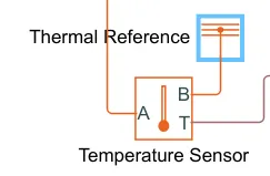
This block measures temperature in a thermal network. There is no heat flow through the sensor. The physical signal port T reports the temperature difference across the sensor. The measurement is positive when the temperature at port A is greater than the temperature at port B.
- Thermal Reference: Used to ground the thermal sensor.
Gear
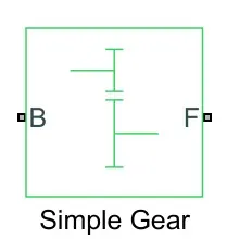
Next, we will model the transmission system of the EV. I have decided to use a 'Simple Gear' block so as to simplify the transmission system parameters. This block models a gear system with a fixed gear ratio with no inertia effects, however we can modify the effects of the meshing of the gear teeth. The simple gear block is shown below:
The mechanical rotational reference block is shown below:
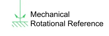
- Mechanical Rotational Reference: Used to ground all the mechanical rotational parts.
Tires
The tires used in this EV model are the 'magic formula' tires. There are several tire blocks that can be used for modelling a vehicle but I have used the magic formula ones because it allows us to model the longitudinal behavior of vehicle tires on highways. They also allow us to model extra effects such as tire inertia, stiffness which allow for greater accuracy of real world conditions. The magic formula tire block is shown below:
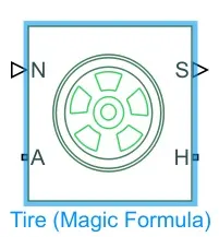
We can see that it has 4 ports and they are:
- N - This port stands for 'Normal' and is the physical signal input port for the normal force acting on the tire and is considered positive in the downwards direction.
- S - This port stands for 'Slip' and is the physical signal output port is that reports the slip acting on the tire.
- A - This port stands for 'Axle' and is the mechanical rotational conserving port for the wheel axle.
- H - This port stands for 'Hub' and is the mechanical translational conserving port for the wheel hub through which the thrust developed by the tires is applied to the vehicle body.
-
Double clicking the magic formula tire block takes us to its parameters.
Main
The image below shows the settings for the main parameters of the magic formula tires:
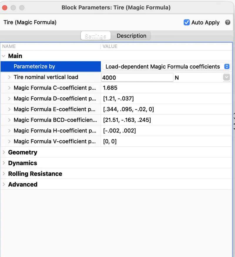
As we can see, we are parameterizing the tires with 'Load dependent Magic Formula coefficients' and the remaining parameters that follow with it are default.
Geometry
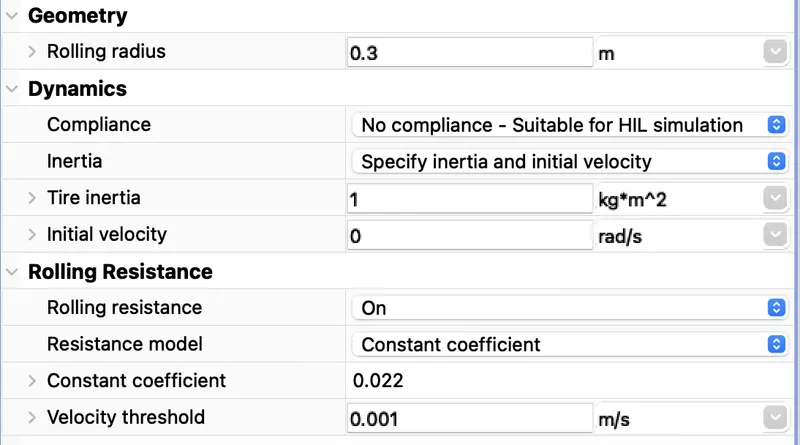
The image below shows the parameters of the tire geometry. There is only one parameter that can be modified and it is the rolling radius and has been set to a nominal value of 0.3m.
-
Dynamics
The next parameters are the dynamics of the magic formula tires. This is where we can model additional effects e.g. tire inertia and the initial velocity if we are modeling to specify those 2 conditions.
-
Here, we can model the rolling resistance parameters on the tires and I have chosen to switch ON the rolling resistance force on the tires. Also, I have selected a constant coefficient of rolling resistance of 0.022 and a velocity threshold of 0.001.
-
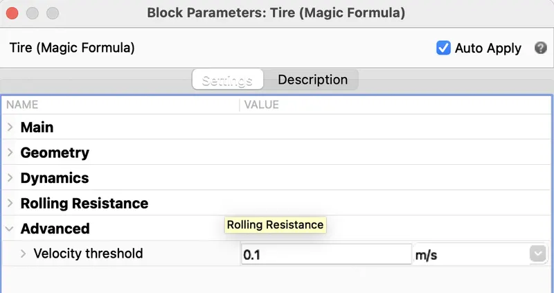
Advanced
Finally, the last parameter for the magic formula tires is the velocity threshold and this has been set to 0.1m/s. Below this speed, the block will not model any of the mentioned effects of motion on to the tire, hence called a 'threshold' velocity.
-
Vehicle Body
To model a vehicle's body, we need to first add the vehicle body block and this is shown below:
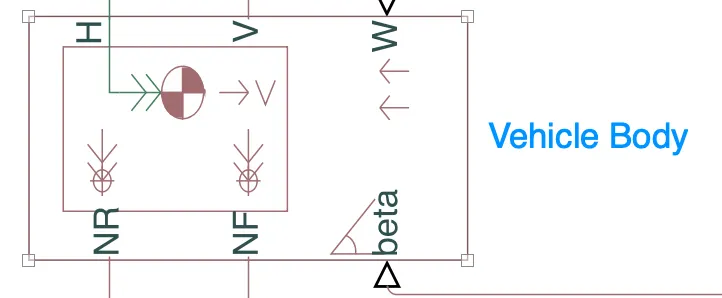
This block contains 6 ports which can be used to model the various aspects of the vehicle body. The ports are mentioned and elaborated below:
- H - This stands for 'Hub' and is used to connect the hubs of the wheels to the main body of the vehicle.
- V - This is a physical signal output port which stands for 'Velocity' and is used to output the speed/velocity at which the vehicle is moving at.
- W - This is a physical signal input port and allows us to model a 'headwind' acting on the vehicle by giving a speed for it.
- NR - This is a physical signal output port to model the rear wheel normal forces.
- NF - This is a physical signal output to model the front wheel normal forces.
- beta - This is a physical signal input port and allows us to model the vehicle on an inclination angle to create the effect of a hill climbing force.
-
If we double click the vehicle body block, we can see and modify its parameters and this is shown in the image below:
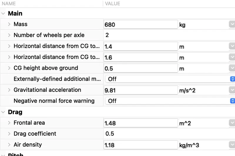
Main :As you can see, we are able to modify various parameters of the vehicle body e.g. mass, number of wheels per axle, distance of the center of gravity to the front and rear axles. These are the main parameters and have been left with the default values assigned when the block was added to the workspace. The next tab shows the parameters for 'Drag' and this is shown below: here the kerb weight of the vehicle is 600kg as the payload weight is 80kg man .
Battery:
| Internal Resistance | 0.0012 ohm |
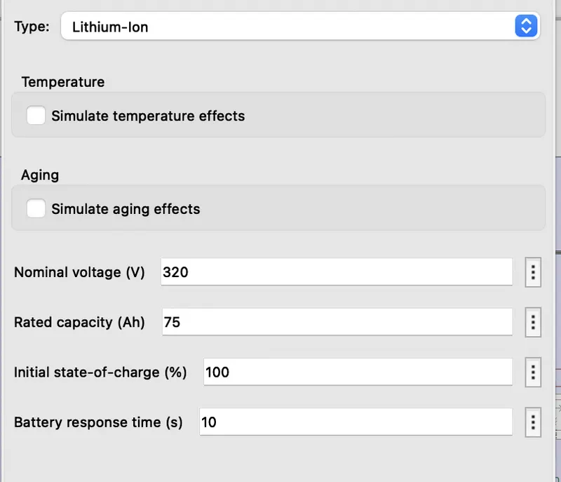
The battery is required to power the controller and motor. The controller uses the battery power according to produce the input given by the motor to obtain maximum speed. The battery is also used to power every electrical component in the vehicle. The battery has two stage one is charging and another one is discharging state. The battery is of 75Ah capacity.
The Nominal voltage of battery is 330 V
Initial SoC is of 100%
The battery as a series internal resistance plus a charge-dependent voltage source defined by:
V=Vnom⋅SoC/1−β⋅(1−SoC)
where SoC is the state of charge and Vnom is the nominal voltage. Coefficient beta is calculated to satisfy a user-defined data point [AH1,V1].
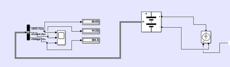
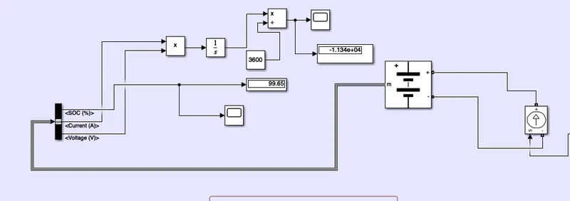
The battery has a positive and negative terminal which is given the voltage-controlled source where the battery consumption is controlled by the motor controller and then it is given to the SOC block.
State of charge (SoC):
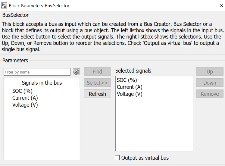
SoC is the percentage or level of battery presents after certain travel or consumption of battery charge by the vehicle. In the designed vehicle battery charge or SOC is calculated by the giving it to the rate transition and then to gain where 1/(nominal battery capacity) then to a discrete-time integrator and it will get minus from the 1 as it is considered a 100% of battery and it is multiplied with 100 to get percentage of battery.
The majority of blocks are simscape blocks where physical to simulink converter is used to convert the physical signal from simscape block to simulink signal.
Results:
1. For FTP75 Drive Cycle:
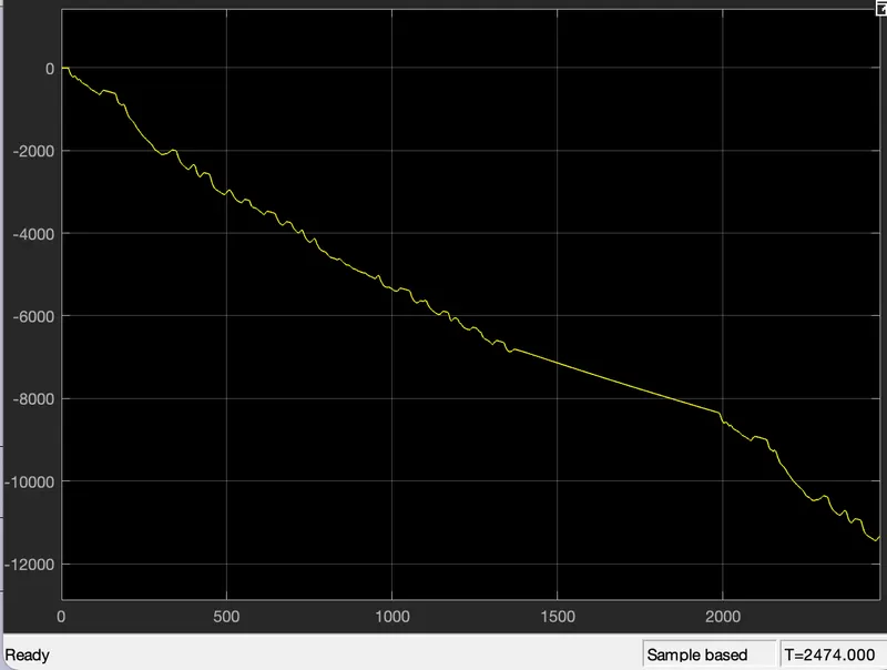
By running the Vehicle with FTP75 Drive cycle for 2474 sec. the distance travelled is 5.95519.44km.">km.
19.44km.">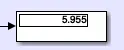
to get the FTP75 results we need get the input to the multiport as 2 then only it switches 2 and enable
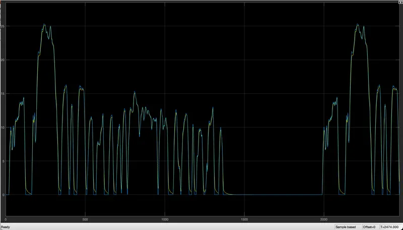
- The actual Speed is approximately followed the 95% of reference Drive cycle.
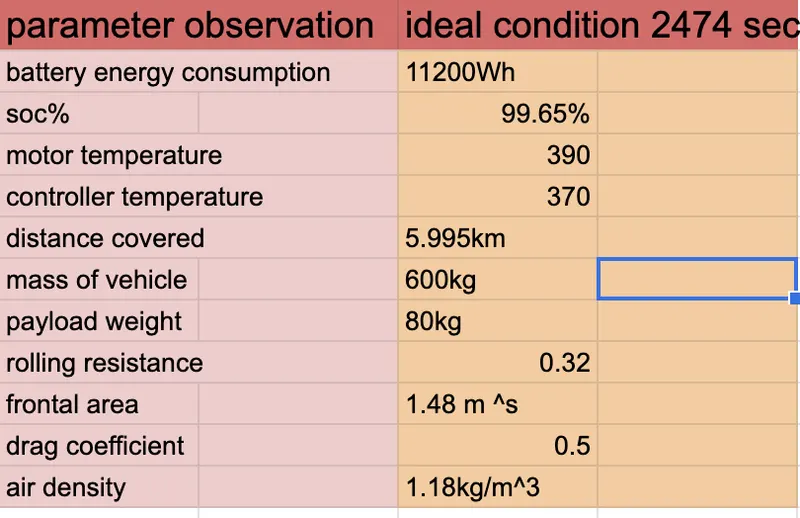
- Energy consumed by the battery is 11200 Wh at the end of the cycle.
- The SoC% of the battery
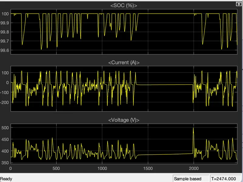
- as we see the state of charge it is not constant and it is fluctuations are and as per driving condition this happens and in this case we the driver input as the FTP75 drive cycle as the soc changes like it charges and discharge as per the driving cycle intially the soc of charge is 100% as vechicle runs its gets discharge and the brake pedal is pressed it charges as renegrative braking. as the end of the simulation the state of charge is 99.65%.
- The Temperature of Motor is increased to 390•C
- The Temperature of Controller is 370C
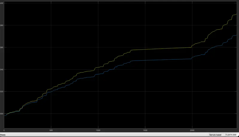
- inthis the blue line represents the controller temperature
- yellow line represents the motor temperature
1. For FTP72 Drive Cycle:
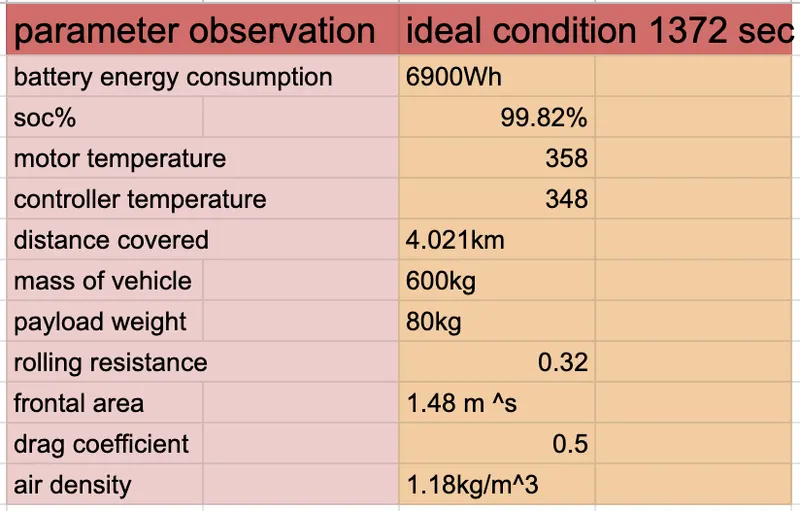
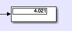
By running the Vehicle with FTP75 Drive cycle for 1372 sec. the distance travelled is 4.02119.44km.">km.
to get the FTP75 results we need get the input to the multiport as 1 then only it switches 1 and enable
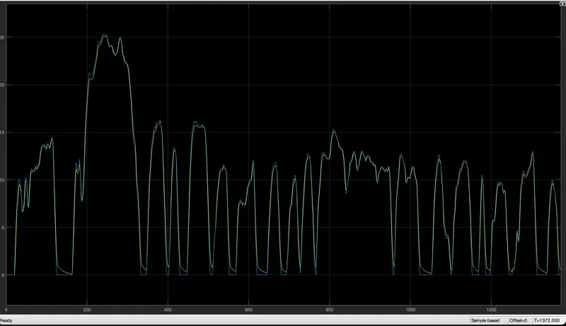
- The actual Speed is approximately followed the 92% of reference Drive cycle.
Energy consumed by the battery is 6900 Wh at the end of the cycle.
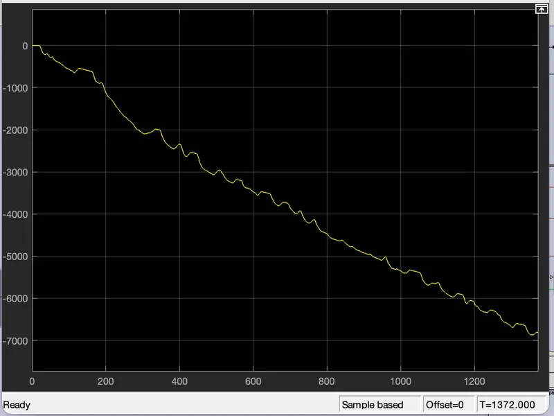
- The SoC% of the battery
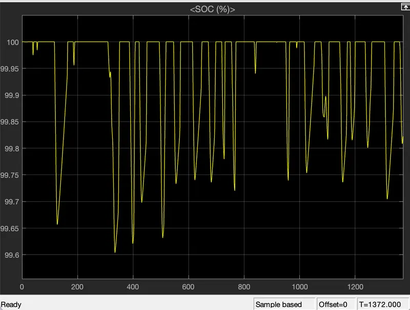
- as we see the state of charge it is not constant and it is fluctuations are and as per driving condition this happens and in this case we the driver input as the FTP75 drive cycle as the soc changes like it charges and discharge as per the driving cycle intially the soc of charge is 100% as vechicle runs its gets discharge and the brake pedal is pressed it charges as renegrative braking. as the end of the simulation the state of charge is 99.82%
- The Temperature of Motor is increased to 358•C
- The Temperature of Controller is 348 C
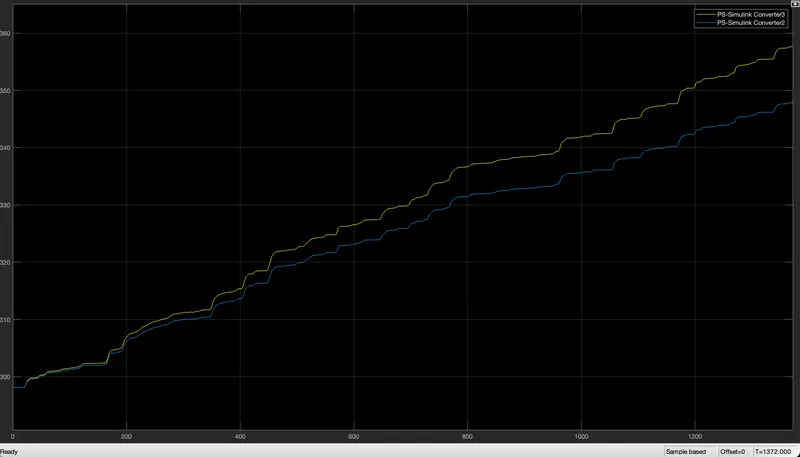
- inthis the blue line represents the controller temperature
- yellow line represents the motor temperature
For WOT Drive cycle:
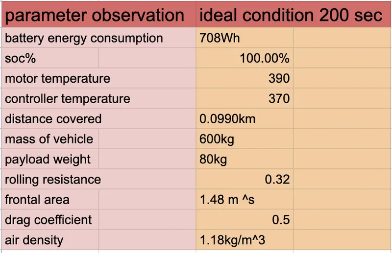
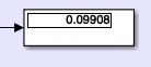
By running the Vehicle with WOT Drive cycle for 200 sec. the distance travelled is 0.09908km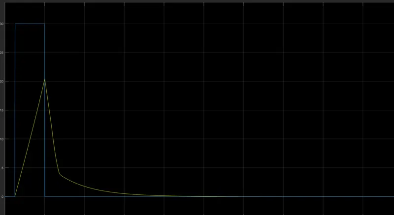
- The actual Speed is approximately followed the 85% of reference Drive cycle.
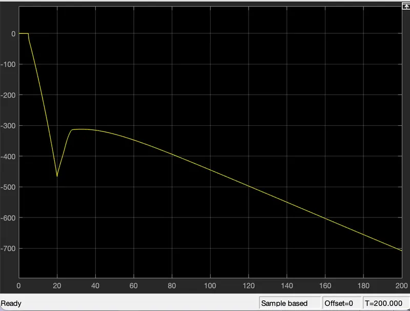
Energy consumed by the battery is 708 Wh at the end of the cycle.
- The SoC% of the battery
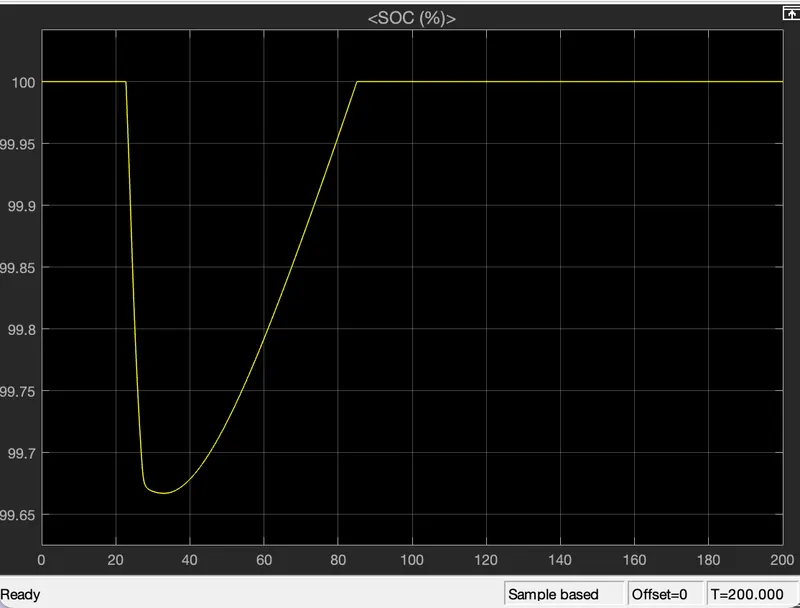
- intial the state of charge is 100% at t=20sec it start discharging as per the drive cycle wot it is full accleration then it discharges to 99.66%when it comes back to it state due to renerative braking again it start charging at t=82. and at the end of the cycle it reaches to 100%.
- The Temperature of Motor is increased to 305.7•C
- The Temperature of Controller is 305.2 C
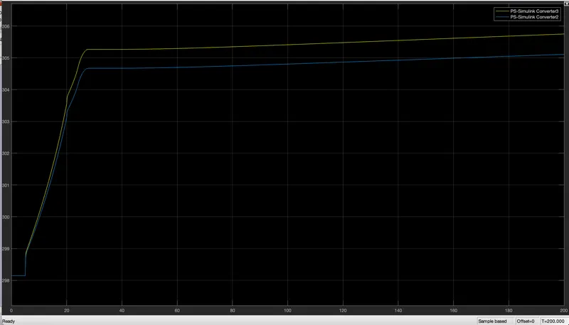
- inthis the blue line represents the controller temperature
- yellow line represents the motor temperature