Final Project: Electric Rickshaw modelling
ELECTRIC RICKSHAW:
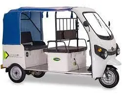
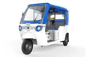
Electric rickshaws (also known as electric tuk-tuks or e-rickshaws or toto or e-tricycles) have been becoming more popular in some cities since 2008 as an alternative to the auto-rickshaws and pulled rickshaws because of their low fuel cost, and less human effort compared to pulled rickshaws. They are being widely accepted as an alternative to petrol, diesel, CNG auto-rickshaws. They are three-wheelers powered by an Electric motor ranging from 650 to 1400 Watts. They are mostly manufactured in India and China, only a few other countries manufacture these vehicles. Battery-run rickshaws could be a low-emitter complimentary transport for the low-income people, who suffer most from a lack of transport facility if introduced in a systematic manner according to experts.
I) AIM:
To create a detailed MATLAB model of an electric rickshaw (three wheel passenger vehicle).
II) OBJECTIVES:
To create an Electric Rickshaw model with following details,
1) Rear wheels to be driven by PM brushed type motor.
2) Assuming efficiency points of motor controller and motor.
3) To create an excel sheet with all input and assumed data.
4) Energy consumption values for three standard driving cycles.
5) Temperature rise of motor and controller for 100 km constant driving at 45 kmph.
III) SYSTEM LEVEL CONFIGURATIONS:
Blocks used to model Vehicle Subsystem:
1) Vehicle Body:
(Simscape - Driveline - Tires & Vehicles)
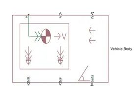
It has a total of six connections, in which V, NF & NR are the physical signal output ports for vehicle velocity, normal front & normal rear wheel forces. The connections W & beta are the physical signal input ports for wind speed & road inclination angle respectively, while connection H is the mechanical translational conserving port associated with the horizontal motion of the vehicle body.
Connection H is connected to a hub part of the tire, V is connected to the feedback velocity of the longitudinal driver block, NR & NF are connected to the rear & front tire of a vehicle. W & beta connections are connected to a constant block & the values of windspeed & inclination angle can be given accordingly.
2) Tire:
(Simscape - Driveline - Tires & Vehicles)
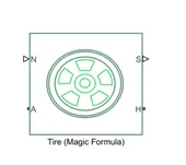
Connection A is the mechanical rotational conserving port for the wheel axle & are connected to both of the front & rear wheels axle. Connection H is the mechanical translational conserving port for the wheel hub & all four tires hub is connected to the hub port of the vehicle body. Connection N is a physical signal input port that applies the normal force acting on the tire & are connected to rear & front wheel . Connection S is a physical signal output port that reports the tire slip.
3) A simple gear block:
(Simscape - Driveline - Gears)
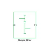
Represents a fixed-ratio gear or gear box. Connections B (base) and F (follower) are mechanical rotational conserving ports. Specify the relation between base and follower rotation directions with the Output shaft rotates parameter. Port F is connected to the axle of a rear wheel & hence it is called as rear wheel drive while port B is given as the input to the dc motor shaft.
4) PS Terminator block:
(Simscape - Foundation library - Physical signals - Sinks)
This block is used to terminate the physical signal output ports ,'S' of the tire which is left unconnected.
5) Inertia:
(Simscape - Foundation library - Mechanical - Rotational Elements)
It represents an ideal mechanical rotational inertia.
6) PS Constant block:
(Simscape - Foundation library - Physical Signals - Sources)
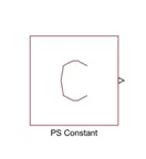
It creates a physical signal constant & accepts both positive & negative values. This block is used to give a constant physical values for wind & inclination angle.
7) Rotational Free End:
(Simscape - Foundation library - Mechanical - Rotational Elements)
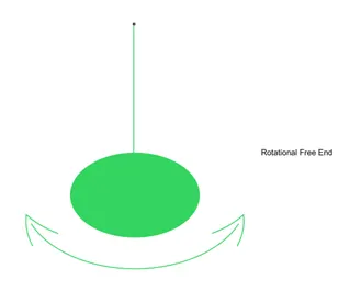
This block represents a mechanical rotational free end. Use it to allow a node to rotate freely without torque. This block can be used to optionally specify initial rotational velocity.
Blocks used to model DC Motor & Power Converter Subsystem:
1) DC Motor:
(Simscape - Electrical - Electromechanical - Brushed Motors)
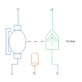
This block represents the electrical and torque characteristics of a DC motor. When a positive current flows from the electrical + to - ports, a positive torque acts from the mechanical C to R ports. Motor torque direction can be changed by altering the sign of the back-emf or torque constants. Port R is connected to the gear box, C to the ground while the +ve & -ve terminals of the motor is connected to the +ve & -ve terminals of the H-bridge respectively. We have enabled the thermal port option to view the temperature of the motor. Port H of the motor (thermal port) is connected to Port A of the temperature sensor.
2)H-Bridge:
(Simscape - Electrical - Semiconductors & Converters - Converters)
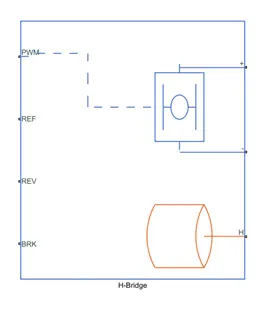
This block represents an H-bridge motor drive. The block can be driven by the Controlled PWM Voltage block in PWM or Averaged mode. In PWM mode, the motor is powered if the PWM port voltage is above the Enable threshold voltage. In Averaged mode, the PWM port voltage divided by the PWM signal amplitude parameter defines the ratio of the on-time to the PWM period. If the REV port voltage is greater than the Reverse threshold voltage, then the output voltage polarity is reversed. If the BRK port voltage is greater than the Braking threshold voltage, then the output terminals are short circuited via one bridge arm in series with the parallel combination of a second bridge arm and a freewheeling diode. Voltages at ports PWM, REV and BRK are defined relative to the REF port. We have enabled the thermal port option to view the temperature of the controller. Port H of the H-bridge (thermal port) is connected to Port A of the temperature sensor.
3) Temperature Sensor:
(Simscape - Foundation Library - Thermal - Thermal Sensors)
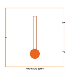
This block measures temperature in a thermal network. There is no heat flow through the sensor. The physical signal port T reports the temperature difference across the sensor. The measurement is positive when the temperature at port A is greater than the temperature at port B.
4) Thermal Reference:
(Simscape - Foundation Library - Thermal - Thermal Elements)
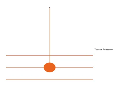
This block represents a reference point in a thermal network where the temperature is equal to absolute zero.
5) Controlled PWM Voltage:
(Simscape - Electrical - Integrated Circuits)
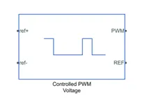
This block creates a Pulse-Width Modulated (PWM) voltage across the PWM and REF ports. The output voltage is zero when the pulse is low, and is equal to the Output voltage amplitude parameter when high. Duty cycle is set by the input value.At time zero, the pulse is initialized as high unless the duty cycle is set to zero or the Pulse delay time is greater than zero.
6) Controlled Voltage Source:
(Simscape - Foundation library - Electrical - Electrical Sources)
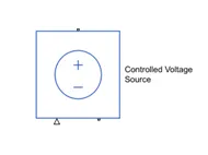
The block represents an ideal voltage source that is powerful enough to maintain the specified voltage at its output regardless of the current passing through it.
7) Current Sensor:
(Simscape - Foundation library - Electrical - Electrical Sensors)
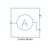
The block represents an ideal current sensor, that is, a device that converts current measured in any electrical branch into a physical signal proportional to the current. Connections + and - are conserving electrical ports through which the sensor is inserted into the circuit. Connection I is a physical signal port that outputs current value.
8) Mechanical Rotational Reference:
(Simscape - Foundation library - Mechanical - Rotational Elements)
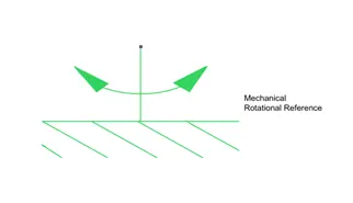
This block represents a mechanical rotational reference point, that is, a frame or a ground. Use it to connect mechanical rotational ports that are rigidly affixed to the frame (ground).
9) Electrical Reference:
(Simscape - Foundation library - Electrical - Electrical Elements)
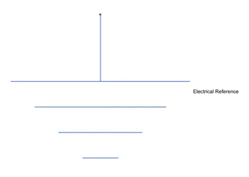
Electrical reference port. A model must contain at least one electrical reference port (electrical ground).
Blocks used to model Battery Subsystem:
1) Battery:
(Simscape - Electrical - Specialized Power Systems - Sources)
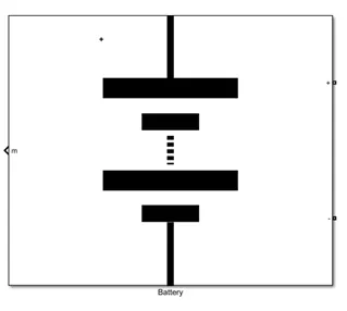
Implements a generic battery model for most popular battery types. Temperature and aging (due to cycling) effects can be specified for Lithium-Ion battery type.
2) Controlled Current Source:
(Simscape - Electrical - Specialized Power Systems - Sources)
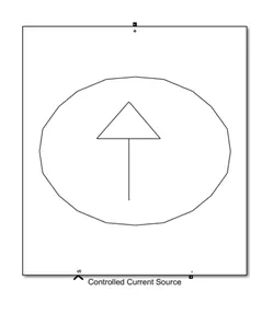
Converts the Simulink input signal into an equivalent current source. The generated current is driven by the input signal of the block.
3) Bus Selector:
(Simulink - Signal Routing)
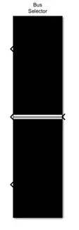
This block accepts a bus as input which can be created from a Bus Creator, Bus Selector or a block that defines its output using a bus object. The left listbox shows the elements in the input bus. Use the Select button to select the output elements. The right listbox shows the selections. Use the Up, Down, or Remove button to reorder the selections. Check 'Output as virtual bus' to output a single bus.
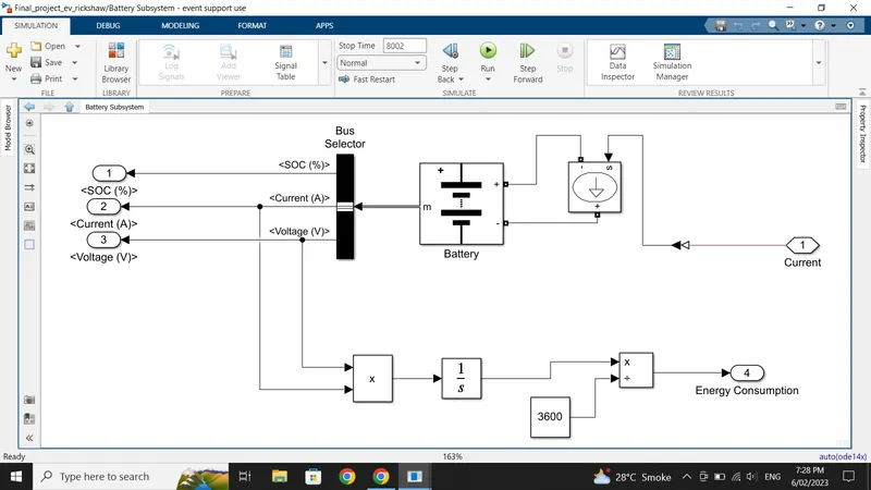
4) The Integrator, Product, Divide & Constant blocks are used for the calculation of Energy Consumed.
5) The Scope & Display blocks used to show the graph of various results.
Blocks used to model Driver Controller & Drive Cycle:
1) Longitudinal Driver:
(Powertrain Blockset - Vehicle Scenario Builder)
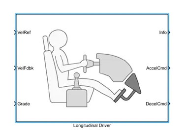
A parametric longitudinal speed tracking controller for generating normalized acceleration and braking commands based on reference and feedback velocities.
2) Multiport Switch:
(Simulink - Signal Routing)
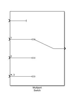
Pass through the input signals corresponding to the truncated value of the first input. The inputs are numbered top to bottom (or left to right). The first input port is the control port. The other input ports are data ports.
3) Drive Cycles:
(Powertrain Blockset - Vehicle Scenario Builder)
It generates a standard or user-specified longitudinal drive cycle. The block output is the vehicle longitudinal speed. In this also we can have multiple drive cycle source.
Here, we have used the following three drive cycles:
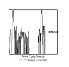
I) FTP75 Drive Cycle:
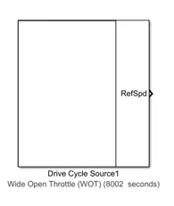
II) Wide Open Throttle (WOT) Drive Cycle:
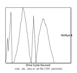
III) Manually made Drive cycle:
4) Converter Blocks:
We have to use an appropriate converter block to convert simulink signals into physical signals or vice versa.
I) Simulink-PS Converter:
(Simscape - Utilities)
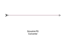
It converts the input simulink signal into a physical signal.
II) PS-Simulink Converter:
(Simscape - Utilities)
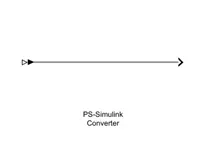
It converts the physical signal into a simulink output signal.
5) The Constant, Integrator, Divide Blocks are used for conversion.
6) The Scope & Display blocks are used to see the graph & display the results respectively.
4) MODEL EXPLANATION & ITS PARAMETERS:
EV car model:
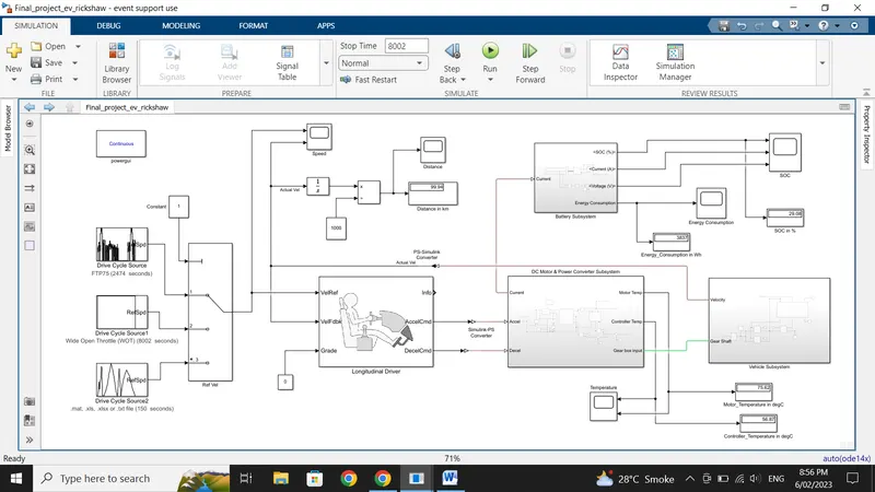
Vehicle Subsystem:
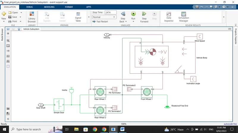
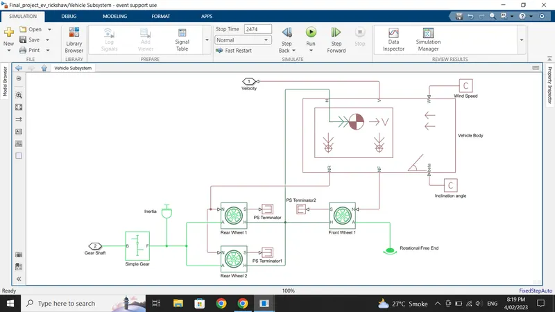
1) In the Vehicle subsystem, we have 'NR' connected to both the rear tire of the vehicle & 'NF' connected to the front tire of the vehicle. 'H' is the hub which is connected to the hub of all three tires. 'V' is the actual velocity of a vehicle where its ouput is connected to a scope via a PS-Simulink converter. 'W' & 'beta', is the wind speed & inclination angle of a vehicle which is given a constant value as per our desire with a constant block.
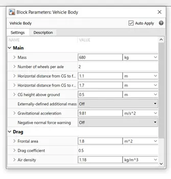
2) In the vehicle body block the parameters are set as shown.
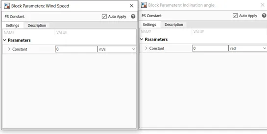
The wind speed & inclination angle is set to 0 i.e. no environment parameters is considered.
3) The tire (magic formula) block is used to design the vehicle wheels, we have consider the first two tire as the rear wheel & the third as the front wheel. The 'H' is hub which is connected together, 'N' is normal force so the rear wheels 'N' port is connected together & 'N' port of front wheel is connected, 'A' is the axle of the wheel & connected in same way as the 'N' port. All tires parameters are set as shown.

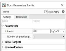
4) Port 'S' represents the slip & can't be left unconnected so a PS terminator block is used to terminate the signal. A vehicle also has some inertia so a inertia block is used & value of inertia is selected as default.
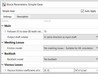
5) A simple gear system is used in order to drive the motor, we have taken teeth ratio as 10 & the gear shaft will rotate in the direction of the motor. The gear shaft output is connected to a input to a DC motor.
DC Motor & Power Converter Subsystem:
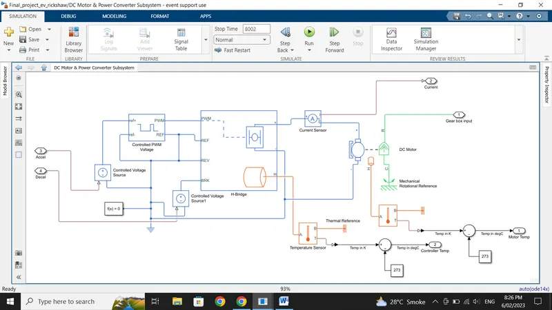
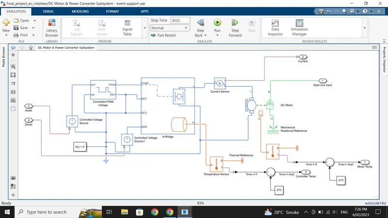
1) We have taken a Permanent magnet brushed type DC motor which converts electrical input signal into rotational mechanical output signal. The green colour of the DC motor is the mechanical part & blue is the electrical part. The mechanical ports are connected to a gear system which is further connected to the rear wheels of the vehicle, so the rear wheels are driven by PM brushed type DC motor & other is connected to a mechanical rotational reference which refers that the motor rotates keeping this quantity as reference.
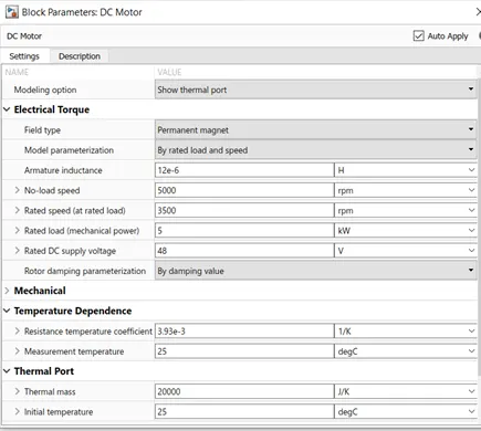
The positive terminal of motor is connected to a positive of H-bridge & negative is connected to a negative of a H-bridge. The thermal port has been enabled shown in orange colour in order to monitor the temperature of the motor which is connected to a temperature sensor, the output of temperature is in Kelvin so further it is converted in degree celsius. The parameters for DC motor are set as shown.
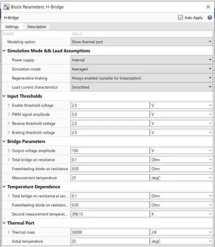
2) The H-bridge is used to control the motor direction. It can rotate the motor in forward & reverse direction thus regenerative braking takes place. The H-bridge is controlled by the PWM technique, thus by changing the width we can control the parameters of H-bridge. The output voltage of H-bridge will be equal to motor input voltage.
In H-bridge parameters we have selected simulation mode as averaged in order to have fast simulation & regenerative braking option is also enabled to get regenerative braking during high deceleration. The thermal port has been enabled shown in orange colour in order to monitor the temperature of the controller which is connected to a temperature sensor, the output of temperature is in Kelvin so further it is converted in degree celsius. The parameters for H-bridge are set as shown.
3) The PWM technique will check the reference value. If reference value is high it will take 1 & if it is low it will take as 0 & accordingly it will adjust the duty cycle & the voltage. Here also simulation mode is selected as average to have fast response.
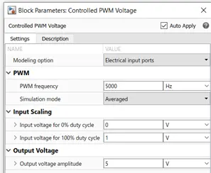
3) Now as the current is not be sensed by the battery input as it is physical signal, a current sensor is used in between H-bridge & a DC motor in order to have a physical current signal.
4) The controlled voltage source is used to have a specified voltage at its output. The acceleration & deceleration command input from longitudinal driver is fed to the controlled voltage source block.
5) While modelling with simscape it is necessary to have solver configuration block connected to a reference which handles the simscape equations.
Battery Subsystem:
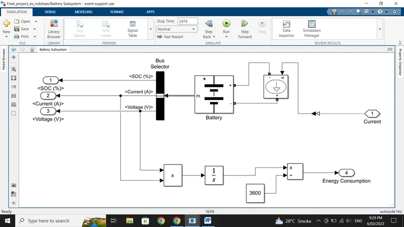
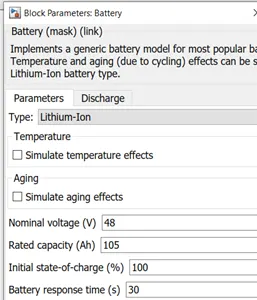
1) A lithium-ion battery is used for an EV vehicle to run which is connected to a controlled current source to have a specified current. Nominal voltage of battery is assumed to be 48 V & its Ah rating is assumed to be 105, while initial state-of-charge is 100% & battery response time is 30 seconds. The discharge values are determined from the nominal parameters of the battery.
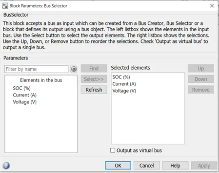
2) The m port of the battery is connected to the bus selector from where we get the SOC, current & voltage values.
3) Further the voltage & current values are multiplied by the product block to get Power in watts & further it is integrated & divided by 3600 to get Energy Consumed in Watt Hours.
Driver Controller & Drive cycle:
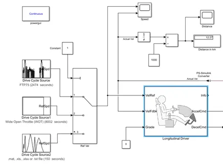
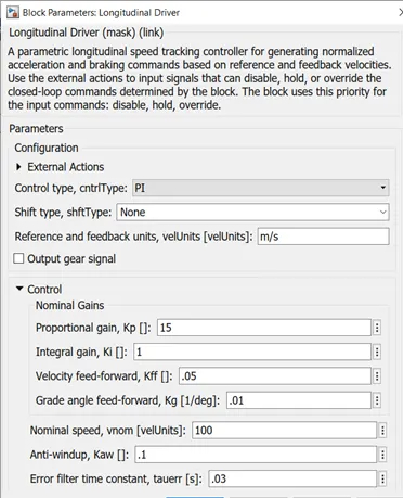
1) The longitudinal driver block is used to have the driver control. It represents the driver input As the longitudinal driver output has physical signal & it can't be sensed by the motor as it has electrical signals, so in order to convert the mechanical signal to electrical signal we have taken the controlled voltage source block. The acceleration is connected to the control PWM & the deceleration terminal is connected to the braking port of the H-bridge which is further connected to the DC motor. The reference velocity is the drive cycle which we have chosen & the feedback velocity is the vehicle velocity i.e. the actual velocity. As we are not considering the gradient, so it has been selected as '0' . The control type is selected as 'PI' control & rest are set as default.
2) We have taken three different drive cycles FTP75, WOT & a custom made drive cycle. To choose any of the drive cycle, multiport switch block is used which takes the input of any one of the drive cycle by giving the number of the port to which the drive cycle is connected accordingly that drive cycle will be selected.
3) The distance is found out in km by integrating the speed (m/s) w.r.t. time & dividing it by 1000.
4) Scope is connected to the different ports to see the results.
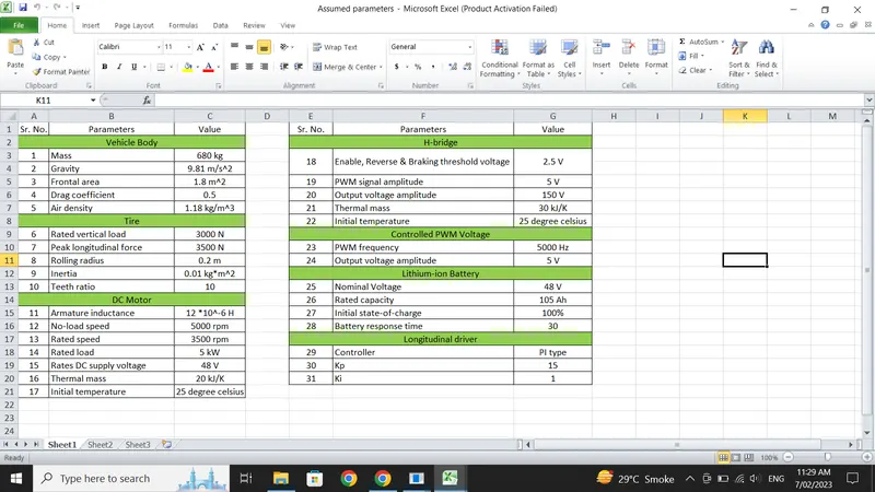
The Input & assumed data has been prepared in an Excel File.
5) RESULTS:
I) For FTP75 Drive Cycle:
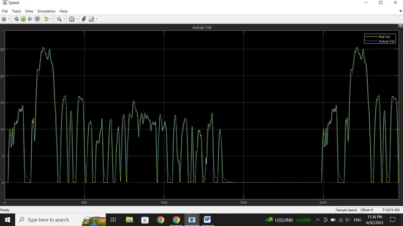
Run the Simulation for 2474 seconds.
The actual velocity (blue) is approximately following the reference velocity (yellow).
Means our modelled electric rickshaw follows the input drive cycle.
The distance travelled is 18.11 km.
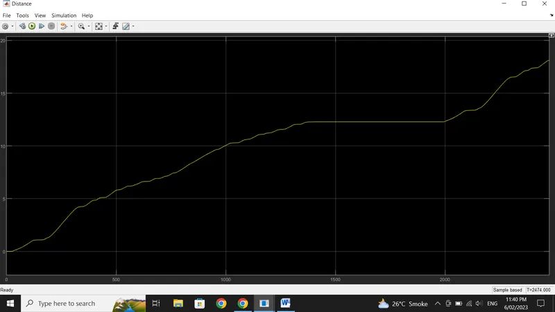
Energy consumed is 953.7 Wh for a distance of about 18.11 km.
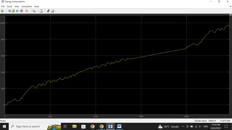
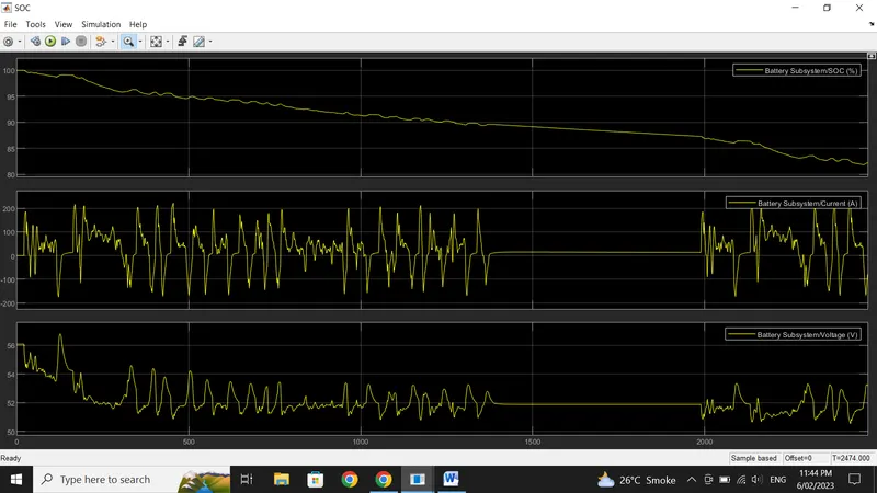
The battery gets discharged from 100 % to 82.22 %. Almost 82.22 % of the battery capacity is remaining after completing this drive cycle. The sudden spikes in SOC graph, represents the regenerative braking. During which the SOC value increases.
The current follows positive and negative profile. Positive being current drawn from the battery and negative being current drawn inside the battery (regeneration). This is where the SOC increases. Also, it is zero for zero speed between 1400 and 2000 seconds (approx.) span.
The motor tempearture is 96.14 degree celsius while the controller temperature is 68.29 degree celsius.
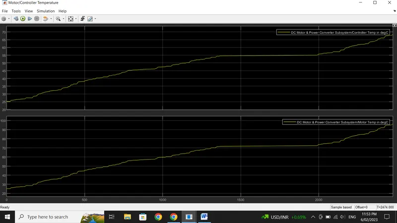
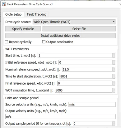
II) For Wide Open Throttle (WOT) Drive Cycle:
For this particular drive cycle it is used to run the vehicle for 100 km at constant 45 kmph speed.
So, the parameters for this block is calculated as follows:
Distance = 100 km ; Speed = 45 kmph
Now, Speed = Distance / Time
Therefore, Time = Distance / Speed
Time = (100 * 3600 ) / 45 ... kmph is converted to kmps
Time = 8000 secoonds
Now accordingly the WOT drive cycle block is set.
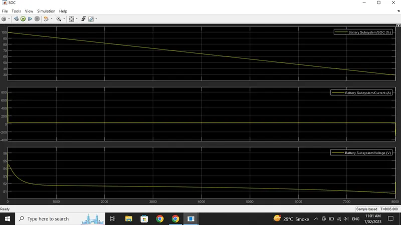
The Simulation is run for 8005 seconds.
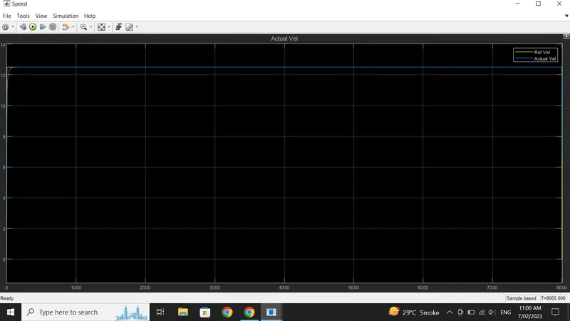
For this drive cycle we can see that it follows the input drive cycle and remains constant at 45 kmph (12.5 m/s) throughout the simulation time. At the beginning it took few seconds to reach 45 Kmph but after reaching it remained constant & starts decelerating after 8001 seconds.
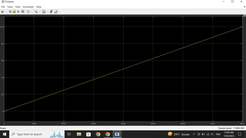
The distance travelled is about 100 km for constant speed of 45 kmph.
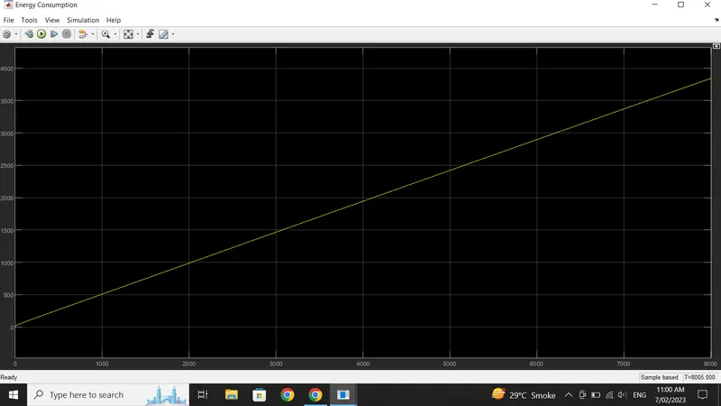
Total energy consumed to travelled a distance of 100 km is 3830 Wh.
The SOC graph for this drive cycle is pretty straight because there is no braking or deceleration taking place . So the SOC value decreased proportional to the distance covered. Only 29.21 % of the battery capacity is remaining after completing this drive cycle.
From the current variation graph we can see that at the start of the simulation , the current reached very high value of 790A to attain the 45 kmph speed in an instant but after that the current drastically decreased & remained constant till the end of the simulation.
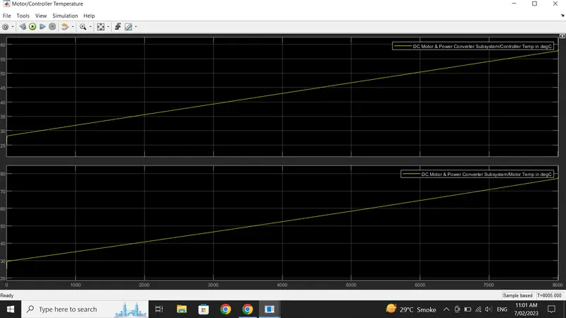
The motor tempearture is 78.13 degree celsius while the controller temperature is 58.31 degree celsius.
III) For Custom Made Drive Cycle:
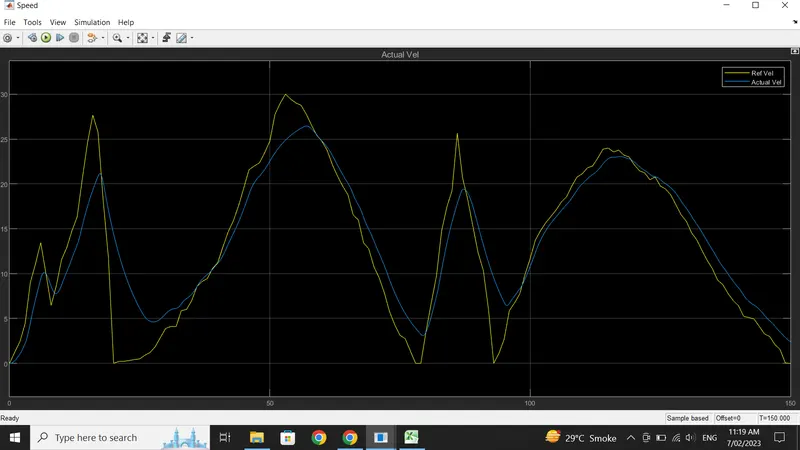
We have made our own duty cycle in Excel sheet from 0 to 150 seconds & the same is imported in the drive cycle source block.
Run the simulation for 150 seconds
The actual velocity is closely following the reference velocity.
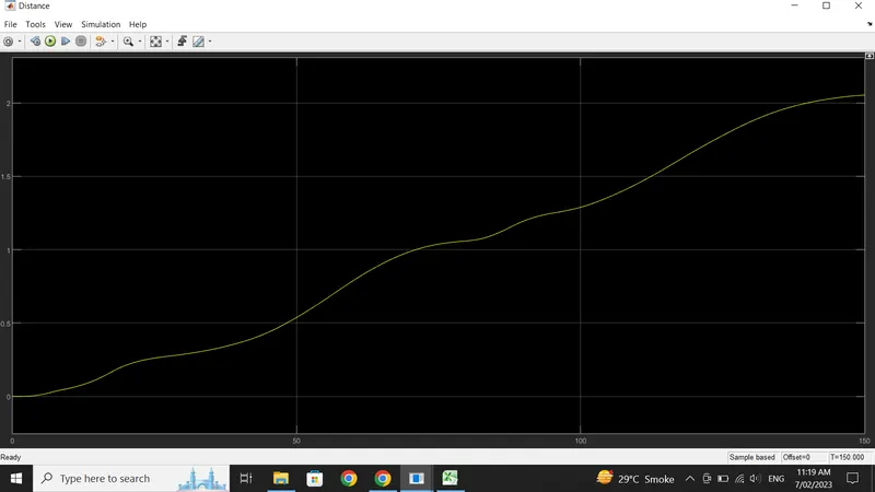
Distance travelled for this drive cycle is 2.053 km
Total energy consumed is 92.57 Wh
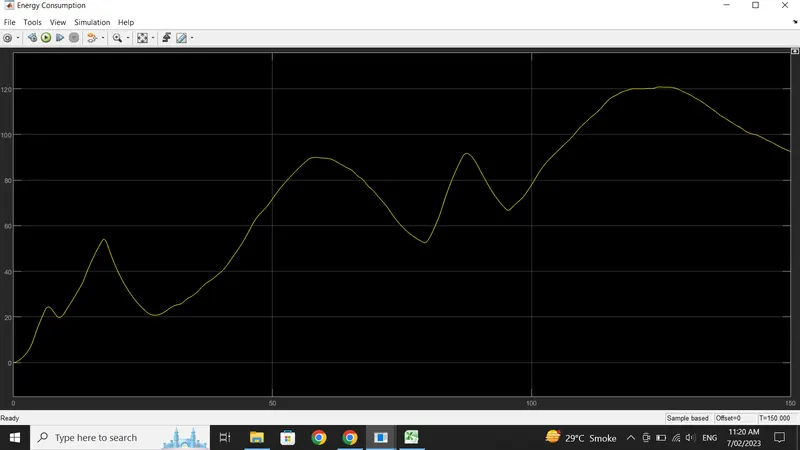
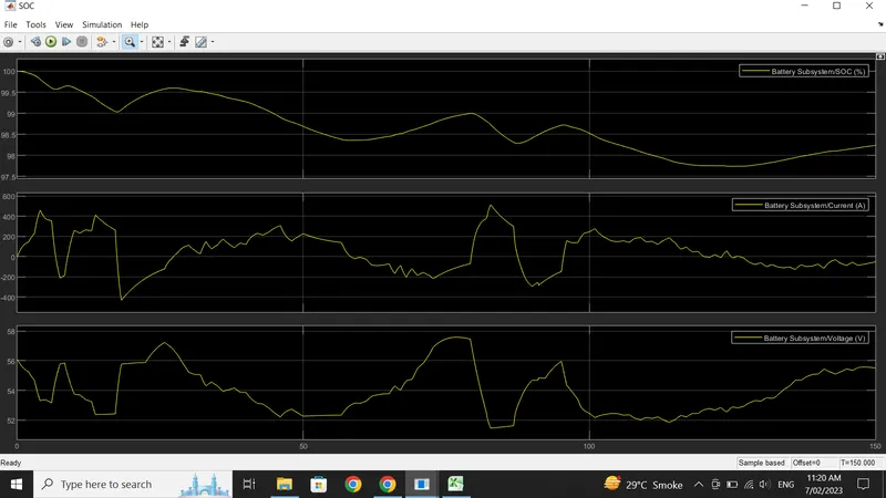
SOC remains is 98.24 % at the end.
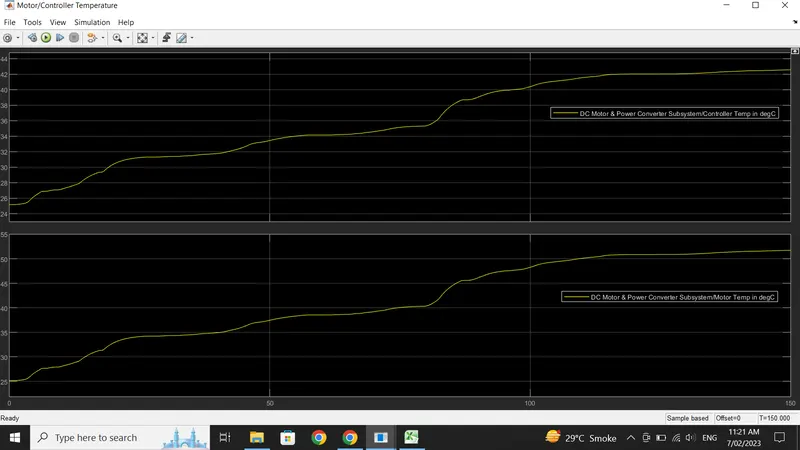
The motor tempearture is 51.73 degree celsius while the controller temperature is 42.47 degree celsius.
6) CONCLUSION:
1) Thus we have successfully modelled an Electric Rickshaw by using Li-ion battery, PM Brushed DC Motor.& saw the result for three different drive cycles.
2) Here, we haven’t used any cooling system inside the model, but in the real time application, the motor, battery & controller temperature is controlled by air cooling. Hence, the temperature of this components is not increased to this extent.
3) We have also determined the variations of Temperature of Motor and Controller, % SoC, Distance travelled, Energy consumed by the vehicle for all the three Reference Drive cycles (i.e.; FTP75, WOT, Manually prepared or Custom made drive cycles).
NOTE: The simulink Model , Excel sheet of assumed parameters & Excel sheet for manually made drive cycles has been attached.