Project-1: Powertrain for aircraft in runways
Part A:
1. Search and list out the total weight of various types of aircrafts.
Answer:
The aircraft gross weight (also known as the all-up weight and abbreviated AUW) is the total aircraft weight at any moment during the flight or ground operation.An aircraft's gross weight will decrease during a flight due to fuel and oil consumption. An aircraft's gross weight may also vary during a flight due to payload dropping or in-flight refuelling.At the moment of releasing its brakes, the gross weight of an aircraft is equal to its takeoff weight.During flight, an aircraft's gross weight is referred to as the en-route weight or in-flight weight.
Structural Weight Limits (structural design weights):
An aircraft's gross weight is limited by several weight restrictions in order to avoid overloading its structure or to avoid unacceptable performance or handling qualities while in operation. Aircraft gross weight limits are established during an aircraft's design and certification period and are laid down in the aircraft's type certificate and manufacturer specification documents.
The absolute maximum weight capabilities of a given aircraft are referred to as the Structural Weight Limits . The structural weight limits are based on aircraft maximum structural capability and define the envelope for the CG charts (both maximum weight and CG limits). An aircraft's structural weight capability is typically a function of when the aircraft was manufactured, and in some cases, old aircraft can have their structural weight capability increased by structural modifications.
1) Maximum design taxi weight (MDTW):
The maximum design taxi weight (also known as the maximum design ramp weight (MDRW)) is the maximum weight certificated for aircraft manoeuvring on the ground (taxiing or towing) as limited by aircraft strength and airworthiness requirements.
2) Maximum design takeoff weight (MDTOW):
Is the maximum certificated design weight when the brakes are released for takeoff and is the greatest weight for which compliance with the relevant structural and engineering requirements has been demonstrated by the manufacturer.
3) Maximum design landing weight (MDLW):
The maximum certificated design weight at which the aircraft meets the appropriate landing certification requirements. It generally depends on the landing gear strength or the landing impact loads on certain parts of the wing structure. The MDLW must not exceed the MDTOW. The maximum landing weight is typically designed for 10 feet per second (600 feet per minute) sink rate at touch down with no structural damage.
4) Maximum design zero-fuel weight (MDZFW):
The maximum certificated design weight of the aircraft less all usable fuel and other specified usable agents (engine injection fluid, and other consumable propulsion agents). It is the maximum weight permitted before usable fuel and other specified usable fluids are loaded in specified sections of the airplane. The MDZFW is limited by strength and airworthiness requirements. At this weight, the subsequent addition of fuel will not result in the aircraft design strength being exceeded. The weight difference between the MDTOW and the MDZFW may be utilised only for the addition of fuel.
5) Minimum flight weight (MFW):
Minimum certificated weight for flight as limited by aircraft strength and airworthiness requirements.
Authorised weight limits:
The authorised or permitted limits may be equal to or lower than the structural design weight limits. The authorised weight limits that can legally be used by an operator or airline are those listed in the AFM and the weight and balance manual. The authorised (or certified) weight limits are chosen by the customer/airline and they are referred to as the "purchased weights". An operator may purchase a certified weight below the maximum design weights because many of the airport operating fees are based on the aircraft AFM maximum allowable weight values. An aircraft purchase price is, typically, a function of the certified weight purchased.
Maximum weights established, for each aircraft, by design and certification must not be exceeded during aircraft operation (ramp or taxying, takeoff, en-route flight, approach, and landing) and during aircraft loading (zero fuel conditions, centre of gravity position, and weight distribution). Weights could be restricted on some type of aircraft depending on the aircraft handling requirements. In addition, the authorised maximum weight limits may be less as limited by centre of gravity, fuel density, and fuel loading limits.
1) Maximum taxi weight (MTW):
The maximum taxi weight (MTW) (also known as the maximum ramp weight (MRW) is the maximum weight authorized for maneuvering (taxiing or towing) an aircraft on the ground as limited by aircraft strength and airworthiness requirements. It includes the weight of taxi and run-up fuel for the engines and the APU. It is greater than the maximum takeoff weight due to the fuel that will be burned during the taxi and runup operations.
2) Maximum takeoff weight (MTOW):
The maximum takeoff weight (also known as the maximum brake-release weight) is the maximum weight authorised at brake release for takeoff, or at the start of the takeoff roll. The maximum takeoff weight is always less than the maximum taxi/ramp weight to allow for fuel burned during taxi by the engines and the APU. In operation, the maximum weight for takeoff may be limited to values less than the maximum takeoff weight due to aircraft performance, environmental conditions, airfield characteristics (takeoff field length, altitude), maximum tire speed and brake energy, obstacle clearances, and/or en route and landing weight requirements.
3) Maximum landing weight (MLW):
The maximum weight authorised for normal landing of an aircraft. The MLW must not exceed the MTOW. The operation landing weight may be limited to a weight lower than the Maximum Landing Weight by the most restrictive of the following requirements:
1)Aircraft performance requirements for a given altitude and temperature:landing field length requirements,approach and landing climb requirements
2)Noise requirements
If the flight has been of short duration, fuel may have to be jettisoned to reduce the landing weight. Overweight landings require a structural inspection or evaluation of the touch-down loads before the next aircraft operation.
Others weight includes:
1) Maximum zero-fuel weight (MZFW):
The maximum permissible weight of the aircraft less all usable fuel and other specified usable agents (engine injection fluid, and other consumable propulsion agents). It is the maximum weight permitted before usable fuel and other specified usable fluids are loaded in specified sections of the airplane.
2) Manufacturers Empty Weight (MEW):
It is the weight of the aircraft "as built" and includes the weight of the structure, power plant, furnishings, installations, systems and other equipment that are considered an integral part of an aircraft. This excludes any baggage, passengers, or usable fuel.
3) Operating Empty Weight (OEW):
It is the basic weight of an aircraft including the crew, all fluids necessary for operation such as engine oil, engine coolant, water, unusable fuel and all operator items and equipment required for flight but excluding usable fuel and the payload.
4) Payload:
It is the carrying capacity of an aircraft. It includes cargo, people, extra fuel. In the case of a commercial airliner, it may refer only to revenue-generating cargo or paying passengers. Regulated Takeoff Weight (RTOW): Depending on different factors (e.g. flap setting, altitude, air temperature, length of runway), RTOW varies for each takeoff. It can never be higher than MTOW.
Below is a table of some of the most common aircraft flying around our skies today:
| Aircraft | Empty Weight | Max Fuel Weight | Max Cargo Weight | Max Gross Takeoff Weight |
|---|---|---|---|---|
| Antanov AN-225 | 628,000 lbs 285,000 kg |
661,400 lbs 300,000 kg |
417,000 lbs 190,000 kg |
1,411,000 lbs 640,000 kg |
| Airbus A380-800 | 611,000 lbs 277,000 kg |
560,000 lbs 254,000 kg |
185,000 lbs 84,000 kg |
1,268,000 lbs 575,000 kg |
| Boeing 747-800 | 485,300 lbs 220,100 kg |
427,400 lbs 194,000 kg |
295,000 lbs 134,000 kg |
987,000 lbs 447,700 kg |
| Airbus A340-500 | 370,000 lbs 168,000 kg |
386,300 lbs 175,000 kg |
119,000 lbs 54,000 kg |
820,000 lbs 372,000 kg |
| Boeing 777-300ER | 370,000 lbs 168,000 kg | 320,800 lbs 145,500 kg | 148,000 lbs 67,100 kg |
776,000 lbs 352,000 kg |
| Boeing 787-10 | 299,000 lbs 135,500 kg | 223,500 lbs 101,500 kg |
126,300 lbs 57,300 kg | 560,000 lbs 254,000 kg |
| Boeing 737-900 | 98,500 lbs 44,700 kg |
53,100 lbs 24,000 kg |
44,600 lbs 20,200 kg |
187,000 lbs 85,000 kg |
| Airbus A320-100 | 93,900 lbs 42,600 kg |
48,700 lbs 22,100 kg |
44,000 lbs 20,000 kg |
150,000 lbs 68,000 kg |
| Embraer 190 | 63,500 lbs 28,800 kg |
28,600 lbs 13,000 kg |
28,800 lbs 13,100 kg |
106,000 lbs 48,000 kg |
| Gulfstream G650 | 54,000 lbs 24,500 kg | 48,200 lbs 21,900 kg | 6,500 lbs 3,000 kg |
100,000 lbs 45,200 kg |
| Bombardier CRJ900 | 48,160 lbs 21,850 kg | 19,600 lbs 8,900 kg | 6,075 lbs 2,760 kg | 80,500 lbs 36,500 kg |
| Bombardier Q400 | 39,300 lbs 17,800 kg |
11,700 lbs 5,300 kg |
18,700 lbs 8,500 kg |
62,000 lbs 28,000 kg |
| Learjet 75 | 13,900 lbs 6,300 kg | 6,060 lbs 2,750 kg |
2,900 lbs 1,300 kg |
21,500 lbs 9,700 kg |
| Cessna Citation CJ4 | 10,300 lbs 4,700 kg | 5,800 lbs 2,650 kg |
2,200 lbs 1,000 kg | 17,200 lbs 7,800 kg |
| Beechcraft King Air B100 | 7,100 lbs 3,200 kg | 3,200 lbs 1,450 kg |
4,150 lbs 1,900 kg |
12,000 lbs 5,400 kg |
| Diamond DA50 RG | 3,200 lbs 1,450 kg |
340 lbs 155 lbs |
1,250 lbs 560 kg |
4,400 lbs 2,000 kg |
| Beechcraft Bonanza G36 | 2,500 lbs 1,150 kg | 450 lbs 200 kg |
850 lbs 385 kg |
3,660 lbs 1,660 kg |
| Cessna 206H | 2,200 lbs 990 kg |
520 lbs 235 kg |
1,150 lbs 520 kg |
3,600 lbs 1,630 kg |
| Sirrus SR22 | 2,250 lbs 1,000 kg | 485 lbs 220 kg |
950 lbs 430 kg |
3,600 lbs 1,630 kg |
| Cessna 172R | 1,700 lbs 770 kg |
380 lbs 170 kg |
560 lbs 255 kg |
2,425 lbs 1,100 kg |
2. Is there any difference between ground speed and air speed?
Answer:
There are two different types of speed when talking about airplanes: Ground speed and Air speed.
Ground speed is the airplane’s speed relative to the surface of the Earth while Air speed is its speed relative to the air it is flying in.
The relationship between Air speed and ground speed is fairly simple. Ground speed is simply the sum of Air speed and wind speed. If the aircraft is flying in the same direction as the wind is blowing, the aircraft experiences tailwind, and its ground speed is higher than its Air speed. On the other hand, if the wind is blowing against the direction the aircraft is traveling in, the aircraft experiences headwind, and its ground speed is lower than its Air speed.
From the above figure;
Ground speed = Air speed + Wind speed
3. Why is it not recommended to use aircraft engine power to move it on the ground at Airport?
Answer:
Pilots and airlines rely on aircraft tugs to perform towing and pushback operations for commercial, private and military aircraft with general ease. The traction design incorporated into aircraft towing equipment means safe movement and stops, even on snow and ice. But there are even more reasons why airlines rely on airport tugs.
1. AIRCRAFT ENGINES CAN CREATE HAZARDOUS CONDITIONS:
When an aircraft's engine is activated, the thrust can create a high-speed wind that can easily cause damage to the airport terminal, surrounding ground vehicles, jetway, baggage and most importantly, ground personnel. Suppressing the use of engines is especially important when towing a large aircraft, as their more powerful thrust capabilities can become dangerous. Engine thrust can easily send any loose items airborne, turn the tiniest grains of dust into hazardous projectiles and create debris that can cause damage to multi-million dollar engines. Additionally, aircraft engines consume a great deal of fuel and generate extreme noise that can be harmful to ground personnel. Using a pushback tug for aircraft is simply a more economical and safer option than running the engines.
2. AIRCRAFT TOWING IS EASIER FOR MAINTENANCE PURPOSES:
Towing and pushback tugs for aircraft are also used to make general maintenance easier for ground personnel. When an aircraft needs to be moved to a hangar for maintenance purposes or is not required for flight, the easiest way is to send an aircraft tug to the tow-in gate for transport. Aircraft towing frees up time for the airline, maintenance team, airport ground controllers and pilots who don't need to waste time getting the engines started. It's also not cost-efficient to start aircraft engines just to reposition an aircraft for maintenance purposes. Typically, ground personnel are trained to only need the aircraft brake system when towing a large aircraft.
3. PILOTS HAVE LIMITED VISIBILITY FROM THE FLIGHT DECK:
Pilots do not have a clear view of the rear from the flight deck and thus rely on aircraft towing equipment for ground pushback when needed. Once the aircraft is perfectly positioned and far from the terminal tow-in gate and other vehicles, the airport tug is disconnected and the aircraft can use its engines and steering to move to the runway for takeoff.
4. TERMINAL TOW-IN GATES ARE CONFINED SPACES:
Aircraft towing from the taxiway occurs with significant time constraints, so pilots and ground personnel are under extreme pressure to navigate the aircraft quickly and efficiently. The tight confines of the terminal tow-in gate combined with the restricted view of the pilots generally always require a tow in order to arrive safely and on time.
Aircraft towing can prevent contact with other structures because ground personnel have much better visibility from the airplane tug. With the aid of ground personnel walking with the wings and tail, the airport tug driver can precisely position the aircraft to ensure it will not hit a structure, vehicle, person or another aircraft. In addition to this, the airplane tug driver is in constant communication with the pilots to ensure the aircraft will brake if an emergency occurs.
5. PUSHBACK TUGS FOR AIRCRAFT ARE REQUIRED FOR GOING IN REVERSE:
Typically, most aircraft cannot move in reverse without the help of aircraft towing equipment. Planes are not designed with a reverse option that pilots can use for backward movement, so pushback tugs for aircraft are the only option when moving aircraft into hangars or away from the terminal building. This is because aircraft are not outfitted with gears or transmission for propulsion, power for movement is derived solely from the engines through thrust. When aircraft tugs are used to tow planes, an airline can maximize safety and optimize efficiency with on-ground operations.
Due to the above reasons, it is not recommended to use aircraft engine power to move it on the ground at Airport.
4. How an aircraft is pushed to runway when its ready to take off?
Answer:
In aviation, pushback is an airport procedure during which an aircraft is pushed backwards away from its parking position, usually at an airport gate by external power. Pushbacks are carried out by special, low-profile vehicles called pushback tractors or tugs.
Although many aircraft are capable of moving themselves backwards on the ground using reverse thrust, the resulting jet balst would cause increased noise, damage to the terminal building or equipment, and hurt airport staff due to high-speed debris. This debris would also be sucked into the engine, as it is in normal use, and cause excessive wear a major cause of wear on aircraft engines is during ground use. A pushback is therefore the preferred method when ground-handling aircraft.
Pushbacks at busy aerodromes are usually subject to ground control clearance to facilitate ground movement on taxiways. Once clearance is obtained, the pilot will communicate with the tractor driver (or a ground handler walking alongside the aircraft in some cases) to start the pushback. To communicate, a headset may be connected near the nose gear.
Since the pilots cannot see what is behind the aircraft, steering is done by the pushback tractor driver and not by the pilots. Depending on the aircraft type and airline procedure, a bypass pin may be temporarily installed into the nose gear to disconnect it from the aircraft's normal steering mechanism.
Once the pushback is completed, the towbar is disconnected, and any bypass pin removed. The ground handler will show the bypass pin to the pilots to make it clear that it has been removed.The pushback is then complete, and the aircraft can taxi forward under its own power.
Moving light aircraft:
Conventional tugs use a tow bar to connect the tug to the nose landing gear of the aircraft. The tow bar is fixed laterally at the nose landing gear, but may move slightly vertically for height adjustment. At the end that attaches to the tug, the tow bar may pivot freely laterally and vertically.
In this manner the tow bar acts as a large lever to rotate the nose landing gear. The tow bar must be long enough to place the tug far away enough to avoid hitting the aircraft and to provide sufficient leverage to facilitate turns.
Towbarless (TBL) tractors do not use a towbar; they scoop up the nose landing gear and lift it off the ground. This avoids the time penalty of connecting/disconnecting a towbar, and entirely removes the cost/complexity of maintaining towbars on the ramp.
The tug itself does not need to be particularly massive the aircraft's nosewheel weight provides the necessary downward force. Lastly, a TBL tug is much shorter (compared to a tug+towbar system) and has only a single pivot point instead of one at either end of the towbar, so it has much simpler and precise control of the aircraft. This is very useful in general aviation settings with a wider variety of aircraft in more confined spaces than their airline counterparts.
So in this way an aircraft is pushed to runway when its ready to take off.
5. Learn about take off power, tyre design, rolling resistance, tyre pressure, brake forces when landing.
Answer:
Take off Power:
For light aircraft, usually full power is used during takeoff. Large transport category (airliner) aircraft may use a reduced power for takeoff, where less than full power is applied in order to prolong engine life, reduce maintenance costs and reduce noise emissions. In some emergency cases, the power used can then be increased to increase the aircraft's performance. Before takeoff, the engines, particularly piston engines, are routinely run up at high power to check for engine-related problems.
Fixed-wing aircraft designed for high-speed operation (such as commercial jet aircraft) have difficulty generating enough lift at the low speeds encountered during takeoff. These are therefore fitted with hif-lift devices often including slats and usually flaps, which increase the camber and often area of the wing, making it more effective at low speed, thus creating more lift. These are deployed from the wing before takeoff, and retracted during the climb. They can also be deployed at other times, such as before landing.
Tyre Design:
Carcass plies are used to form the tire. They are sometimes called casing plies. An aircraft tyre is constructed for the purpose it serves.
1.They support the weight of an aircraft while it is on the ground.
2.It also provides the necessary traction for braking and stopping of an aeroplane.
3.Tyre also helps to absorb the shock of landing and provide cushioning the roughness of takeoff, roll-out, and taxi operations.
Unike an automobile or truck tyre, it does not have to carry a load for a long period of continuous operation. However, an aircraft tyre absorbs the high impact loads of landing, and also it’s operating at high speeds for a short time when required.
Retreading: Retreading is methods of restoring a worn tyre by renewing the tread area or by renewing the tread area plus one or both sidewalls. Repairs are included in the tyre retreading process.
Load Rating: Load rating is the maximum permissible load at a specified inflation pressure.
Ply Rating: Ply Rating is used to identify the maximum recommended load rating and inflation pressure for a specified tyre. It is an index of tyre strength.
Speed Rating: The speed rating is the maximum takeoff speed to which the tyre has been tested.
Skid Depth: Skid depth is the distance between the tread surface and the deepest groove as measured in the mould
Aircraft tyres must have an approved speed and load rating and have sufficient clearance when retracted through landing gear to allow for tyre growth. Tyre growth is the increase in the size of the tyre due to centrifugal forces at high speed
Aircraft tyres may be Tube-type or Tubeless:
Tubeless tyres are more advantageous over tube-type. There is no longer the use of tube-type tyre in recent aviation. Nowadays all airliners are using tubeless tyres. Tubeless that are meant to be used without a tube has the word TUBELESS on the sidewall of the tyre
Aircaft tyres may be Radial or Bias:
Almost all airliners are using Radial tyre. Bias is an older design, and it’s mainly used for road vehicles. Radial tyres have the word RADIAL on the sidewall. Radial tires are more expensive than bias-ply tyres. Radial tires are in demand because of their lower life cycle cost and long term value
Aircraft Tyre Standards:
Each tyre manufacturer produces their own designs of the tyre with different tread patterns, wear patterns, wear limits etc, and in some cases, different names for the same part of the tyre. But all tyres must meet the approved standards before being accepted by the FAA or CAA.
All commercial aircraft tyres approved under FAA Requirement Technical Standard Order (TSO) C62. A TSO is a minimum performance standard for specified materials, parts, and appliances used on civil aircraft
Rolling Resistance:
Rolling Resistance is the force per unit vehicle weight required to move the vehicle on level ground at a constant slow speed where aerodynamic drag (air resistance) is insignificant and also where there are no traction (motor) forces or brakes applied. In other words, the vehicle would be coasting if it were not for the force to maintain constant speed. This broad sense includes wheel bearing resistance, the energy dissipated by vibration and oscillation of both the roadbed and the vehicle, and sliding of the wheel on the roadbed surface (pavement or a rail)
Rolling resistance is the combination of forces that work against the forward motion of your vehicle. The weight of the vehicle, gravity and inertia, the amount of friction between the tires and the road surface, and air drag all play a part.The force that resists the motion of a body rolling on a surface is called the rolling resistance or the rolling friction.
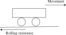
The Rolling Resistance Force is defined by the following equation:
Frr = Crr * m *g
where;
Frr = Rolling Resistance Force
Crr = Rolling Resistance coefficient
m = mass of a vehicle in kg
g = acceleration due to gravity in m/s^2
Crr is the force needed to push (or tow) a wheeled vehicle forward (at constant speed on a level surface, or zero grade, with zero air resistance) per unit force of weight.
Tyre Pressure:
The typical airliner tire can handle a 38-ton load. It can meet the ground 500 times before needing a re-tread. The high-flying rubber is typically inflated to 200 psi, roughly six times what you put in an automobile tire, and the tires on an F-16 fighter are pumped to 320 psi.
The tires themselves aren't terribly large. A Boeing 737 rides on 27x7.75 R15 rubber. That means it is 27 inches in diameter, 7.75 inches wide, and wrapped around a 15-inch wheel. The sidewalls aren't terribly thick, and the strength of the tire lies in the cords embedded below the tread. They're typically nylon, and more recently a variety known as aramid. Each layer of the casing contributes to its load bearing and air pressure resisting capabilities.
In the first moments after a plane touches down, the tires are skidding, not rolling. The airplane essentially drags them down the runway until their rotational velocity matches the velocity of the plane. That's why they smoke upon landing. The stoutest tires are rated for speeds of up to 288 mph.
Brake Forces:
Aircraft brakes stop a moving aircraft by converting its kinetic energy to heat energy by means of friction between rotating and stationary discs located in brake assemblies in the wheels. Brakes provide this critical stopping function during landings to enable airplanes to stop within the length of the runway. They also stop aircraft during rejected takeoff events, in which an attempted takeoff is canceled as the airplane is rolling down the runway before it lifts off from the ground due to engine failure, tire blowout, other system failure or direction from air traffic control.
How aircraft brakes work:
The most common type of brake used on aircraft is the disc brake. Disc brakes function by exploiting friction between rotating and stationary discs inside the brake.
Upon receiving a command signal to brake from the pilot depressing a foot pedal or from the autobrake system actuators in the brake move a piston to squeeze the discs together, generating a frictional force that slows the rotation of the wheel. The friction between the discs generates heat as the aircraft’s kinetic energy is converted to heat energy. In this function, the brakes act as a heat sink, absorbing tremendous amounts of heat as the aircraft sheds kinetic energy. During RTO stops, the temperature of carbon disc brakes can exceed 1,800° C.
Part B:
6. A. With necessary assumptions, calculate the force and power required to push / pull an aircraft by a towing vehicle.
Answer:
Following Assumptions were made for Calculating Aircraft parameters:
1)Mass of the Vehicle (m) = 85000 kg
2)Velocity (v) = 15 kmph
3)Rolling Resistance Coefficient (urr) = 0.015
4)Acceleration dur to gravity (g) = 9.81 m/s^2
5)Air density (rho) = 1.32 kg/m^3
6)Frontal Area (A) = 120 m^2
7)Drag Coefficient (Cd) = 0.25
8)Time (t) = 10 seconds
I) Calculations of Various Forces & Powers for Aircraft:
1)Rolling Resistance Force (Frr):
Frr = urr * m * g
Frr = 0.015 * 85000 * 9.81
Frr = 12507.75 Newtons
Rolling Resistance Power (Prr):
Prr = Frr * v
v = 15 kmph = (15 * 1000) / 3600 = 4.17 m/s
Prr = 12507.75 * 4.17
Prr = 52157.31 Watts
Prr = 52.15 kW
2)Aerodynamic Drag Force (Fad):
Fad = 0.5 * rho * A * Cd * v^2
Fad = 0.5 * 1.32 * 120 * 0.25 * (4.17)^2
Fad = 344.30 Newtons
Aerodynamic Drag Force Power (Pad):
Pad = Fad * v
Pad = 344.30 * 4.17
Pad = 1435.73 Watts
Pad = 1.43 kW
3)Acceleration Force (Fa):
Fa = m * a
where, a= acceleration of aircraft
a = velocity / time = 4.17 / 10
a = 0.417 m/s^2
Fa = 85000 * 0.417
Fa = 35445 Newtons
Acceleration Power (Pa):
Pa = Fa * v
Pa = 35445 * 4.17
Pa = 147805.65 Watts
Pa = 147.80 kW
Force required by an aircraft (Far) = Frr + Fad + Fa
Far = 12507.75 + 344.30 + 35445
Far = 48297.05 Newtons
Tractive Power required by an aircraft (Par) = Prr + Pad + Pa
Par = 52.15 + 1.43 + 147.80
Par = 201.38 kW
Following Assumptions were made for Calculating Towing Vehicle parameters:
1)Mass of the Vehicle (m) = 12000 kg
2)Velocity (v) = 13 kmph
3)Rolling Resistance Coefficient (urr) = 0.015
4)Acceleration dur to gravity (g) = 9.81 m/s^2
5)Air density (rho) = 1.32 kg/m^3
6)Frontal Area (A) = 25 m^2
7)Drag Coefficient (Cd) = 0.25
8)Time (t) = 10 seconds
II) Calculations of Various Forces & Powers for Towing Vehicle:
1)Rolling Resistance Force (Frr):
Frr = urr * m * g
Frr = 0.015 * 12000 * 9.81
Frr = 1765.8 Newtons
Rolling Resistance Power (Prr):
Prr = Frr * v
v = 13 kmph = (13 * 1000) / 3600 = 3.61 m/s
Prr = 1765.8 * 3.61
Prr = 6374.538 Watts
Prr = 6.37 kW
2)Aerodynamic Drag Force (Fad):
Fad = 0.5 * rho * A * Cd * v^2
Fad = 0.5 * 1.32 * 25 * 0.25 * (3.61)^2
Fad = 53.76 Newtons
Aerodynamic Drag Force Power (Pad):
Pad = Fad * v
Pad = 53.76 * 3.61
Pad = 194.07 Watts
Pad = 0.19 kW
3)Acceleration Force (Fa):
Fa = m * a
where, a= acceleration of towing vehicle
a = velocity / time = 3.61 / 10
a = 0.361 m/s^2
Fa = 12000 * 0.361
Fa = 4332 Newtons
Acceleration Power (Pa):
Pa = Fa * v
Pa = 4332 * 3.61
Pa = 15638.52 Watts
Pa = 15.64 kW
Force required by a Towing Vehicle (Ftv) = Frr + Fad + Fa
Ftv = 1765.8 + 53.76 + 4332
Ftv = 6151.56 Newtons
Tractive Power required by a Towing Vehicle (Ptv) = Prr + Pad + Pa
Ptv = 6.37 + 0.19 + 15.64
Ptv = 22.2 kW
Total Force (F) = Far + Ftv
= 48297.05 + 6151.56
=54448.61 Newtons
Total Power (P) = Par + Ptv
= 201.38 + 22.2
=223.58 kW
Therefore, the Total Force required to push/pull an aircraft by a towing vehicle is 54448.61 Newtons &
the Total Power required to push/pull an aircraft by a towing vehicle is 223.58 kW.
B. Develop the model for the calculated force and power using Simulink.
Answer:
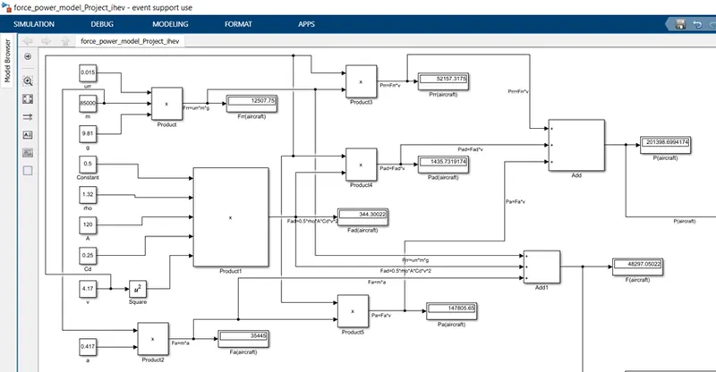
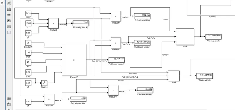
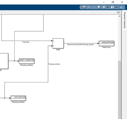
Blocks used for modeling the forces & power in Simulink are:
Constant block, Product block, Square block, Add block & Display block.
Following is the formula to calculate force & power:
1)Rolling Resistance Force (Frr) = urr*m*g
2)Aerodynamic Drag Force (Fad) = 0.5*rho*A*Cd*v^2
3)Acceleration Force (Fa) = m*a
4)Rolling Resistance Power (Prr) = Frr*v
5)Aerodynamic Drag Power (Pad) = Fad*v
6)Acceleration Power (Pa) = Fa*v
1)The assumed parameters values is been put in the constant block & then multiplied using a Product block to get various Forces of aircraft.
2)The force output is then multiplied by velocity using product block to get the various power of Aircraft.
3)All 3 Forces (Frr, Fad, Fa) are then added by using Add block to get the Total Force required by an aircraft.
4)Similarly all 3 Powers (Prr, Pad, Pa) are added using Add block to get the Total Power required by an aircraft.
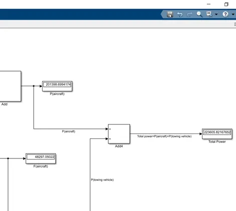
5)Similar model made for towing vehicle
6)The total force by an aircraft & towing vehicle is then added using Add block to get the Total Force required.
7)Similar, the total power by an aircraft & towing vehicle is added using Add block to get the Total Power required.
8)The display block is used to display the results of various Forces & Power calculated.
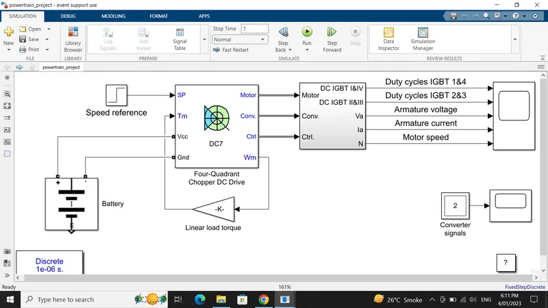
7. A. Design an electric powertrain with type of motor, it’s power rating, and energy requirement to fulfill aircraft towing application in Simulink. Estimate the duty cycle range to control the aircraft speed from zero to highest. Make all required assumptions. Prepare a table of assumed parameters. Draw a block diagram of powertrain.
(Hint :DC7 Block)
Answer:
From Question 6.A, we have calculated The Total Force required to push/pull an aircraft by a towing vehicle is 54448.61 Newtons & the Total Power required to push/pull an aircraft by a towing vehicle is 223.58 kW.
Assuming, the radius of a wheel to be 0.7 m, Gear Ratio to be 12 & transmission efficiency to be 95%
Therefore, torque required (T) = (F * r) / (G * nt)
where, F = Total Force in Newton
r = radius of the wheel in m
G = Gear ratio
nt = transmission efficiency
T = (54448.61 * 0.7) / (12 * 0.95)
T = 3343.33 N-m
Based on our calculation we have selected the Rawsun Power Uninterrupted Electric Motor RDHD20000 AC Motor.
Motor Rating:
Product Name:Rawsun Electric Motor RDHD20000
Rated Power:300 kW ; Rated Torque:1500 N-m ; Peak Speed:3500 rpm
Voltage:700 V ; Current:350 A ; Phase:3 phase
Input Power (Pin) = V * I
Pin = 700 * 350
Pin = 245000 Watts = 245 kW
Now, duty cycle to control the aircraft speed from zero to highest i.e. 4.17 m/s
d = Po / Pin
where, d= duty cycle
Po = output power
Pin= input power
d = 223.58 / 245
d = 0.91
So, the duty cycle range to control the aircraft speed will be from 0 to 0.91
Now, let us assume that time taken by a towing vehicle to tow an aircraft to be 5 mins = 0.08 hrs
So, Energy consumed by a towing vehicle (E) = Po * t
E = 223.58 * 0.08
E = 17.88 kWh
Assuming Battery Voltage = 600V, Rated Capacity = 150Ah
Following is the table of assumed parameters:
| Sr. No | Parameters | Assumed Values |
| 1 | Radius of a wheel | 0.7 m |
| 2 | Gear ratio | 12 |
| 3 | Transmission Efficiency | 95% |
| 4 | Time taken by towing vehicle | 5mins = 0.08 hrs |
| 5 | Battery Voltage | 600 V |
| 6 | Rated Capacity of Battery | 150 Ah |
Simulink Model:
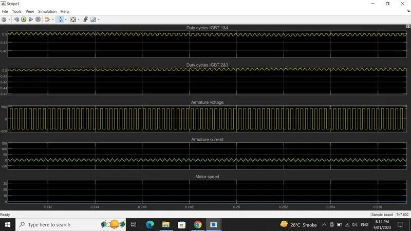
Output Waveforms:
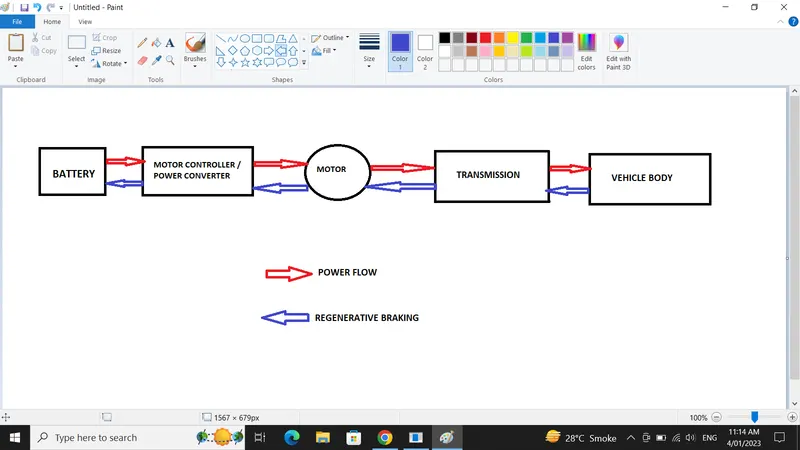
Basic Block diagram of Powertrain:
The following block diagram has been made in paint & pasted here.
1)The battery pack is made up of multiple lithium-ion cells & stores the energy needed to run the vehicle.
2)The battery DC voltage is converted to AC with the help of Power Converter (Inverter) & the power transfer is managed by a Motor Controller that controls the frequency & magnitude of the voltage .
3)The Motor then converts the electrical energy to mechanical energy that is further delivered to the wheels of a vehicle (vehicle body) via single ratio transmission.
B. Also, Design the parameters in excel sheet.
Answer:
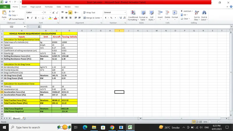
ALL THE REQUIRED FILES HAVE BEEN ATTACHED FOR YOUR REFERENCE