Week-11 Challenge: Braking
1. For a defined driving cycle, calculate the energy required for braking.
Solution:
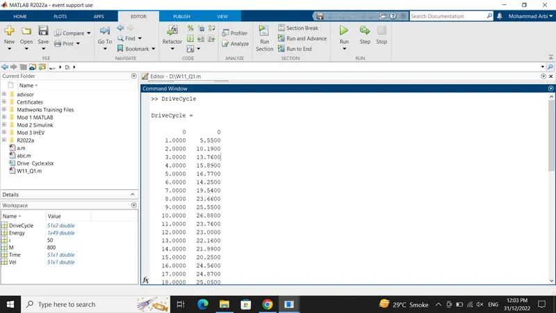
We have made a drive cycle in excel from 0 to 50 seconds Time & respective velocity in m/s.
The drive cycle made in excel has been saved in workspace using Import data option.
MATLAB Program for calculating braking energy for a defined Drive Cycle & its result:
1)We have assumed Mass of vehicle=800kg & Time & velocity values have been imported from drive cycle.
2)Implement 'for loop' & checking the condition where the initial velocity Vel(i) is greater than the final velocity Vel(i+1) if it satisfy then calculate braking energy by the formula:
Energy = 0.5 * M * (Vi - Vf)^2
where, M = Mass of Vehicle in kg
Vi = Initial velocity in m/s
Vf = Final velocity in m/s
3)Then calculate braking energy for that lenght of drive cycle
4)Calculate Total braking energy required for a drive cycle using 'sum' command & print the result
5)Plot the drive cycle & label the axes.
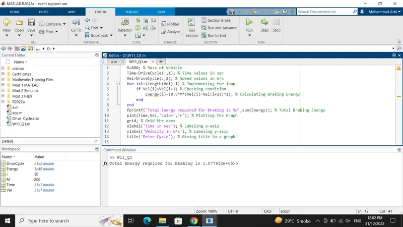
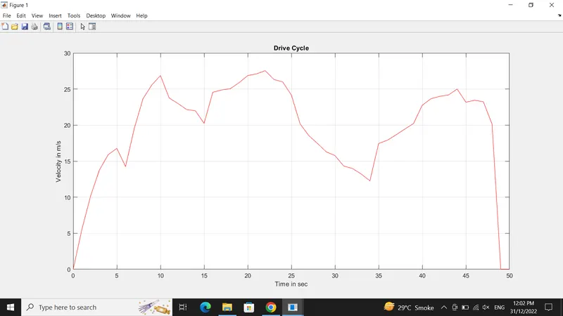
So, from the above MATLAB program the total braking energy required for a particular drive cycle is 1.877932e+05 which is 187793.2 Joules = 187.7932 kJ
2. Why electric motor can’t develop braking torque at high speed similar to starting? How electric and mechanical brakes are coordinated?
Solution:
Electrical Braking is usually employed in applications to stop a unit driven by motors in an exact position or to have the speed of the driven unit suitably controlled during its deceleration. Electrical braking is used in applications where frequent, quick, accurate or emergency stops are required.
Regenerative Braking:
The input power of the induction motor drive is given by the formula:
Pin = 3 * V* Is * cos(fi(s))
Where fi(s) is the phase angle between stator phase voltage and the stator phase current Is. For motoring operation, the phase angle is always less than the 90 degree. If the rotor speed becomes greater than synchronous speed, then the relative speed between the rotor conductor and air gap rotating field reverse.
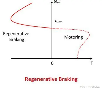
This reverse the rotor induces emf, rotor current and component of stator current which balances the rotor ampere turns. When the fi(s) is greater than the 90 degree, then the power flow to reverse and gives the regenerative braking. The magnetising current produced the air gap flux.
The nature of the speed torque curve is shown in the figure above. When the supply frequency is fixed, the regenerative braking is possible only for speeds greater than synchronous speed. With a variable frequency speed, it cannot be obtained for speed below synchronous speed.
The main advantage of regenerative braking is that the generated power is fully used. And the main drawback is that when fed from a constant frequency source the motor can not employ below synchronous speed.
Sometimes after accelerating you can't reach the maximum torque. The reason is that no matter how much the current loop wants to increase current (proportional to torque) by increasing the PWM duty cycle of the power stage, the Vmotor is too close to Vbemf and therefore current can't increase more.This situation does not occur at the beginning of an acceleration because most of the torque is used to increase the kinetical energy of the load (and motor). But when the speed is already high and no extra load is applied it is not possible to increase the torque.
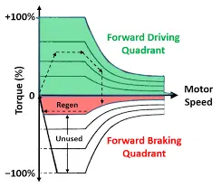
Peak Acceleration Torque and Peak Deceleration torque are not equal for Electric Vehicle Motor. So the Peak Torque during acceleration and the Peak torque during deceleration or braking are not equal. Acceleration is usually higher, at low speed we get higher Torque but at high speed the value of the torque gets lower. So we cannot say that the motor which is producing 7Nm Torque for Acceleration can also produce -7Nm of Braking Torque. So because we are Operating the Motor in Field Weakening region or we are operating the Motor above base speed we must know that the torque is compromised or the torque value is lower
Electric motor can't develop braking torque at high speed similar to starting, because Braking Torque of an EV Motor is not as high as the Acceleration Torque. Therefore Regenerative braking cannot happen so effectively that we can get all the power back to the battery.
Mechanical Braking:
Mechanical brakes are applied by brake shoes which are pressed with force against the wheel of the train. In mechanical braking, the braking force is generally produced by means of piston-cylinder arrangement. The movement of the piston is transmitted to the brake shoes through a system of levers.
Electric Braking:
In electric braking, the kinetic energy of the moving parts of the motor is converted into electrical energy which is either dissipated in a resistor or returned to the supply source. Thus, electric braking is a system of braking in which a braking action is applied to an electric motor by causing it to act as a generator.
In an electric Motor the Total Brake distribution is in two aspects which are Electrical Brake which is called Regenerative Brake and Mechanical Brake or Classical Brake with hydraulic cylindrical system. Brake Force distribution must be uniform, If the Regenerative braking power requirement is more than the charging limit of the battery or more than regenerative capacity of the machine we must apply Mechanical brakes as well. In practical case the combination of these two is applied. So usually it is combined response of Mechanical brake and Regenerative brake. The reason for how these brake force are combined, that particular phenomena is called Brake Control Strategies. There are two Brake Control Strategies, which are
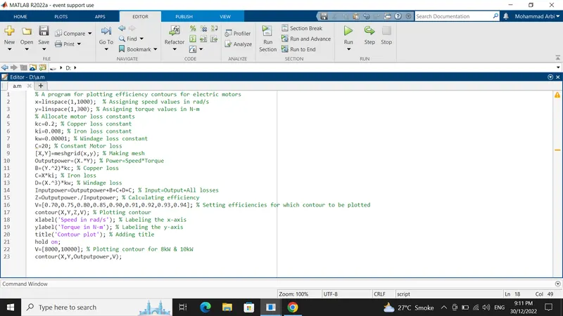
1)Assign the array values in a particular range for speed & torque. Here we have assign 1 to 1000 for speed & 1 to 300 values for torque.
2)Allocate the values to the motor loss constants.
We have given constant values as:
Copper loss constant (kc) = 0.2
Iron loss constat (ki) = 0.008
Windage loss constant (kw) = 0.00001
Motor loss constant (C) = 20
3)Make the mesh using Meshgrid function.
4)Calculate the outpower power: Po = Speed * Torque
5)Calculate all losses:
Copper loss (Cu) = kc * (T)^2 ; where T is the torque
Iron loss (Fe) = ki * Speed
Windage loss (W) = kw * (Speed)^3
6)Calculate Input power = Output power + All losses (Cu + Fe +W + C)
7)Calculate efficiency = Output power / Input power
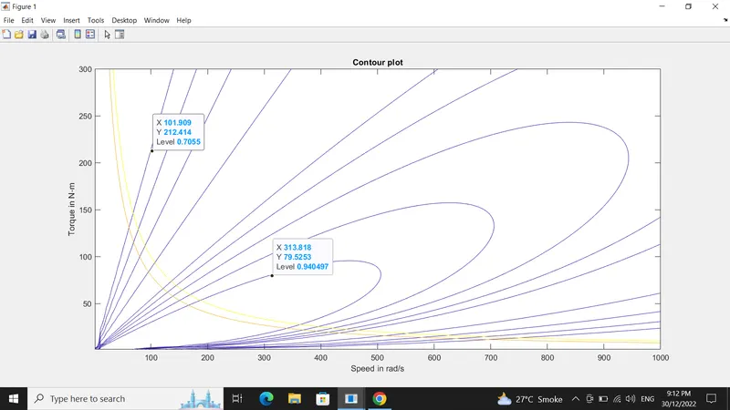
8)Set different efficiencies for which the contour to be plotted
9)Plot the contour using 'contour' command for given torque, speed & efficiency values.
10)Label the x & y axis & give title for the graph
11)Now plot the contour for the required output power.