Final Project: Design of an Electric Vehicle
Electric Vehicle: EVs are vehicles that are either partially or fully powered on electric power. Electric vehicles have low running costs as they have less moving parts for maintaining and also very environmentally friendly as they use little or no fossil fuels (petrol or diesel).
Block diagram / Components of EV Model:
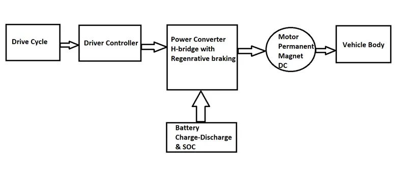
1) Vehicle Body:
it consists of tyres, transmission system & a body of a vehicle. The transmission sytem used to transfer the mechanical power from the electric motor to the wheels, through a gearbox. The advantage of electric cars is that they do not require multi-speed transmissions. The transmission efficiency should be high to avoid power loss.
2) DC Motor:
The motor converts the electrical energy into kinetic energy. This energy rotates the wheels. An important feature of an electric motor is the regenerative braking mechanism. This mechanism slows down the vehicle by converting its kinetic energy into another form, and storing it for future use. While accelerating an EV, the electric motor operates in the motoring mode and the flow of power is from the battery to the wheels of the EV. Hence the battery discharges in the motoring mode. However, while braking an EV, the motor acts as a generator (regenerative braking) and the flow of power takes place from the wheels of the EV to the battery. Hence the batteries get charged during the braking.
3) Power Converter:
The traction battery pack delivers a constant voltage. But different components of the vehicle has different requirements. The DC-DC distributes the output power that is coming from the battery to a required level. It also provides the voltage required to charge the auxiliary battery. An auxiliary battery of appropriate voltage is normally used in electric cars to supply power to all accessories like lights, horns, etc.
4) Battery:
It powers the electric motor of an electric vehicle. The battery acts as an electrical storage system. It stores energy in the form of DC current. The range will be higher with increasing kW of the battery. The life and operation of the battery depends on its design. The batteries used for EVS are rechargeable.
The following three batteries are used in different EVs:
1) Lead-acid batteries.
2) Nickel-Metal Hydride (NiMH) batteries.
3) Lithium-ion (Li-ion) batteries.
5)Driver Controller:
It performs the regulation of electrical energy from the batteries to the electric motors. The pedal set by the driver determines the speed of the car and frequency of variation of voltage that is input to the motor. It also controls the torque produced. They provide perfect speed control along with optimum use of energy while accelerating and braking.
6) Drive Cycle:
A driving cycle is a series of data points representing the speed of a vehicle versus time. A drive cycle is a series of trips, usually one or two, that a vehicle is required to undergo so that the powertrain control module (PCM) can trigger the monitoring systems into readiness states allowing for retrieval of diagnostic data.
1) SYSTEM LEVEL CONFIGURATIONS:
Blocks used to model Vehicle Subsystem:
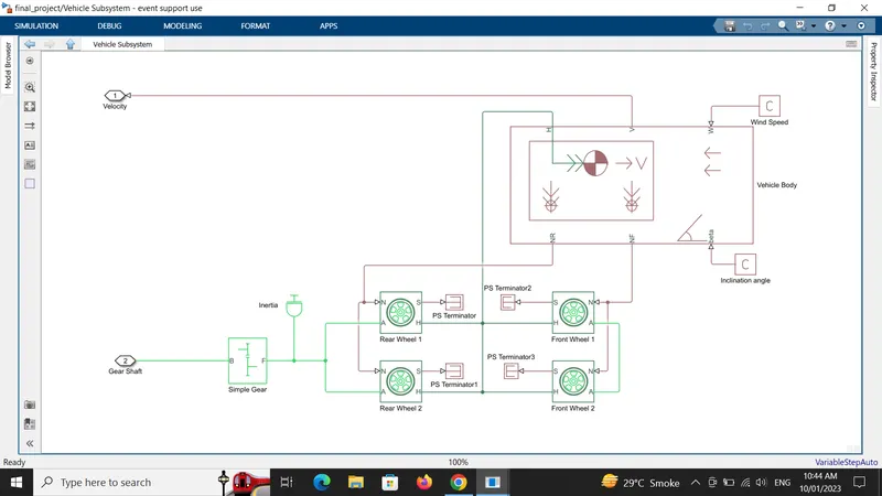
1) Vehicle Body:
(Simscape - Driveline - Tires & Vehicles)
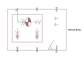
It has a total of six connections, in which V, NF & NR are the physical signal output ports for vehicle velocity, normal front & normal rear wheel forces. The connections W & beta are the physical signal input ports for wind speed & road inclination angle respectively, while connection H is the mechanical translational conserving port associated with the horizontal motion of the vehicle body.
Connection H is connected to a hub part of the tire, V is connected to the feedback velocity of the longitudinal driver block, NR & NF are connected to the rear & front tire of a vehicle. W & beta connections are connected to a constant block & the values of windspeed & inclination angle can be given accordingly.
2) Tire:
(Simscape - Driveline - Tires & Vehicles)
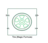
Connection A is the mechanical rotational conserving port for the wheel axle & are connected to both of the front & rear wheels axle. Connection H is the mechanical translational conserving port for the wheel hub & all four tires hub is connected to the hub port of the vehicle body. Connection N is a physical signal input port that applies the normal force acting on the tire & are connected to rear & front wheel . Connection S is a physical signal output port that reports the tire slip.
3) A simple gear block:
(Simscape - Driveline - Gears)
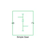
Represents a fixed-ratio gear or gear box. Connections B (base) and F (follower) are mechanical rotational conserving ports. Specify the relation between base and follower rotation directions with the Output shaft rotates parameter. Port F is connected to the axle of a rear wheel & hence it is called as rear wheel drive while port B is given as the input to the dc motor shaft.
4) PS Terminator block:
(Simscape - Foundation library - Physical signals - Sinks)
This block is used to terminate the physical signal output ports ,'S' of the tire which is left unconnected.
5) Inertia:
(Simscape - Foundation library - Mechanical - Rotational Elements)
It represents an ideal mechanical rotational inertia.
6)PS Constant block:
(Simscape - Foundation library - Physical Signals - Sources)
It creates a physical signal constant & accepts both positive & negative values. This block is used to give a constant physical values for wind & inclination angle.
Blocks used to model DC Motor & Power Converter Subsystem:
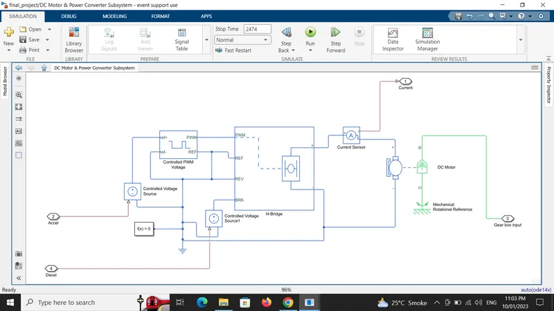
1) DC Motor:
(Simscape - Electrical - Electromechanical - Brushed Motors)
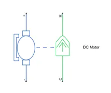
This block represents the electrical and torque characteristics of a DC motor. When a positive current flows from the electrical + to - ports, a positive torque acts from the mechanical C to R ports. Motor torque direction can be changed by altering the sign of the back-emf or torque constants. Port R is connected to the gear box, C to the ground while the +ve & -ve terminals of the motor is connected to the +ve & -ve terminals of the H-bridge respectively.
2)H-Bridge:
(Simscape - Electrical - Semiconductors & Converters - Converters)
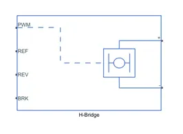
This block represents an H-bridge motor drive. The block can be driven by the Controlled PWM Voltage block in PWM or Averaged mode. In PWM mode, the motor is powered if the PWM port voltage is above the Enable threshold voltage. In Averaged mode, the PWM port voltage divided by the PWM signal amplitude parameter defines the ratio of the on-time to the PWM period. If the REV port voltage is greater than the Reverse threshold voltage, then the output voltage polarity is reversed. If the BRK port voltage is greater than the Braking threshold voltage, then the output terminals are short circuited via one bridge arm in series with the parallel combination of a second bridge arm and a freewheeling diode. Voltages at ports PWM, REV and BRK are defined relative to the REF port.
3) Controlled PWM Voltage:
(Simscape - Electrical - Integrated Circuits)
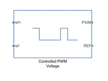
This block creates a Pulse-Width Modulated (PWM) voltage across the PWM and REF ports. The output voltage is zero when the pulse is low, and is equal to the Output voltage amplitude parameter when high. Duty cycle is set by the input value.At time zero, the pulse is initialized as high unless the duty cycle is set to zero or the Pulse delay time is greater than zero.
4) Controlled Voltage Source:
(Simscape - Foundation library - Electrical - Electrical Sources)
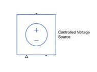
The block represents an ideal voltage source that is powerful enough to maintain the specified voltage at its output regardless of the current passing through it.
5) Current Sensor:
(Simscape - Foundation library - Electrical - Electrical Sensors)
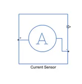
The block represents an ideal current sensor, that is, a device that converts current measured in any electrical branch into a physical signal proportional to the current. Connections + and - are conserving electrical ports through which the sensor is inserted into the circuit. Connection I is a physical signal port that outputs current value.
6) Mechanical Rotational Reference:
(Simscape - Foundation library - Mechanical - Rotational Elements)
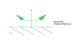
This block represents a mechanical rotational reference point, that is, a frame or a ground. Use it to connect mechanical rotational ports that are rigidly affixed to the frame (ground).
Blocks used to model Battery Subsystem:
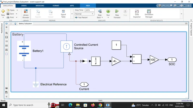
1) Battery:
(Simscape - Electrical - Sources)
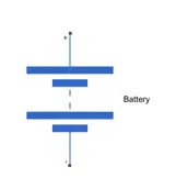
This block models a battery. If you select Infinite for the Battery charge capacity parameter, the block models the battery as a series internal resistance and a constant voltage source. If you select Finite for the Battery charge capacity parameter, the block models the battery as a series internal resistance plus a charge-dependent voltage source.
2) Controlled Current Source:
(Simscape - Foundation library - Electrical - Electrical Sources)
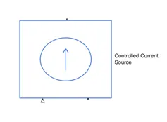
The block represents an ideal current source that is powerful enough to maintain the specified current through it regardless of the voltage across it.
3) The Integrator, Add, Gain & Constant blocks are used for the calculation of the SOC.
4) The Scope & Display blocks used to show the graph & the values of the calculated SOC in %.
Blocks used to model Driver Controller & Drive Cylcle:
1) Longitudinal Driver:
(Powertrain Blockset - Vehicle Scenario Builder)
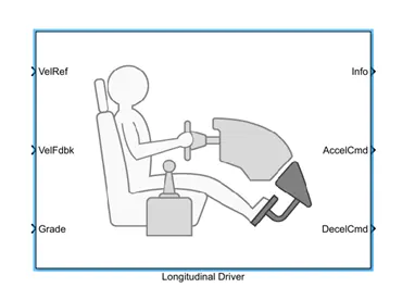
A parametric longitudinal speed tracking controller for generating normalized acceleration and braking commands based on reference and feedback velocities.
2) Multiport Switch:
(Simulink - Signal Routing)
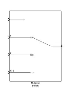
Pass through the input signals corresponding to the truncated value of the first input. The inputs are numbered top to bottom (or left to right). The first input port is the control port. The other input ports are data ports.
3) Drive Cycles:
There are different drive cycles available that we can use as per our convenience.
I) Drive Cycle Source:
(Powertrain Blockset - Vehicle Scenario Builder)
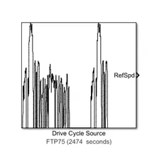
It generates a standard or user-specified longitudinal drive cycle. The block output is the vehicle longitudinal speed.
In this also we can have multiple drive cycle source.
II) Signal Builder:
(Simulink - Sources)
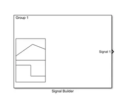
In this we can create our own drive cycle by varying the speed & time as per our needs.
III) From Spreadsheet:
(Simulink - Sources)
We can have manually make drive cycle in excel & the same can be use here.
4) Converter Blocks:
We have to use an appropriate converter block to convert simulink signals into physical signals or vice versa.
I) Simulink-PS Converter:
(Simscape - Utilities)
It converts the input simulink signal into a physical signal.
II) PS-Simulink Converter:
(Simscape - Utilities)
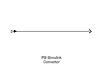
It converts the physical signal into a simulink output signal.
5) The Constant, Integrator, Add, Divide, Gain Blocks are used for conversion & SOC calculation.
6) The Scope & Display blocks are used to see the graph & display the results respectively.
1) MODEL EXPLANATION & ITS PARAMETERS:
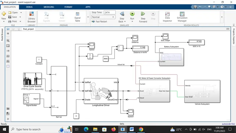
EV car model:
Vehicle Subsystem:
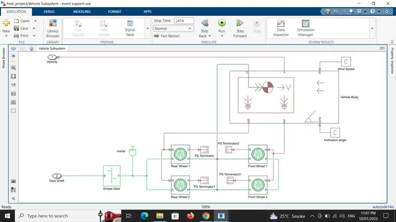
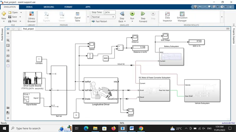
1)In the Vehicle subsystem, we have 'NR' connected to both the rear tire of the vehicle & 'NF' connected to both the front tire of the vehicle. 'H' is the hub which is connected to the hub of all four tires. 'V' is the actual velocity of a vehicle where its ouput is connected to a scope via a PS-Simulink converter. 'W' & 'beta', is the wind speed & inclination angle of a vehicle which is given a constant value as per our desire with a constant block.
2) In the vehicle body block the parameters are set to default values & the wind speed & inclination angle is set to 0 i.e. no environment parameters is considered.
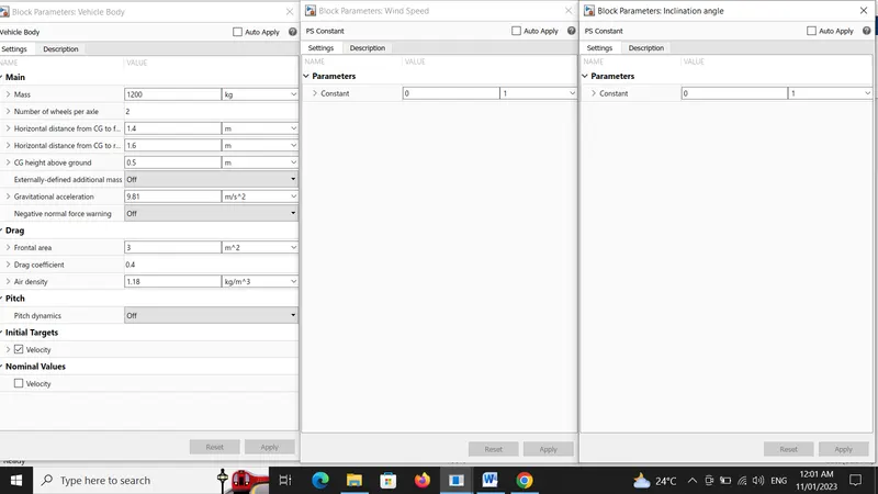
3)The tire (magic formula) block is used to design the vehicle wheels, we have consider the first two tire as the rear wheel & the other two as the front wheel. The 'H' is hub which is connected together, 'N' is normal force so the rear wheels 'N' port is connected together & 'N' port of front wheels connected together, 'A' is the axle of the wheel & connected in same way as the 'N' port. All tires parameters are set to default.
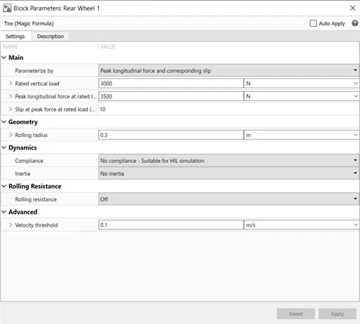
4) Port 'S' represents the slip & can't be left unconnected so a PS terminator block is used to terminate the signal. A vehicle also has some inertia so a inertia block is used.
5) A simple gear system is used in order to drive the motor, in which we have taken gear teeth as 6 & the gear shaft will rotate in the direction of the motor. The gear shaft output is connected to a input to a DC motor.
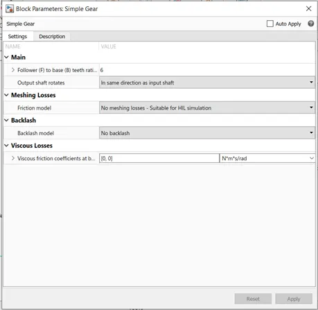
DC Motor & Power Converter Subsystem:
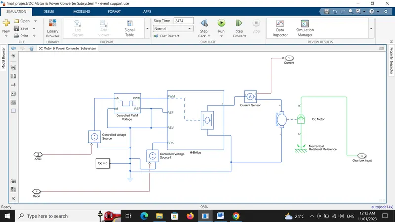
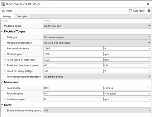
1) We have taken a simple Permanent magnet type DC motor which converts electrical input signal into rotational mechanical output signal. The green colour of the DC motor is the mechanical part & blue is the electrical part. The mechanical ports are connected to a gear system & other is connected to a mechanical rotational reference which refers that the motor rotates keeping this quantity as reference.
The positive terminal is connected to a positive of H-bridge & negative is connected to a negative of a H-bridge. The no-load speed & rated speed is assumed to be 7000 rom & 5000 rpm respectively. Supply voltage is given as 300 V & 60 kW mechanical power is been considered. Rest parameters are set to default.
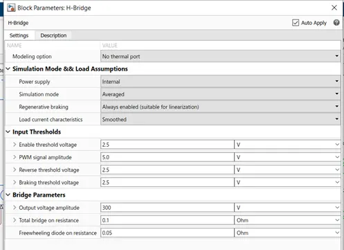
2) The H-bridge is used to control the motor direction. It can rotate the motor in forward & reverse direction thus regenerative braking takes place. The H-bridge is controlled by the PWM technique, thus by changing the width we can control the parameters of H-bridge. The output voltage of H-bridge will be equal to motor input voltage.
In H-bridge parameters we have selected simulation mode as averaged in order to have fast simulation & regenerative braking option is also enabled to get regenerative braking during high deceleration. The output voltage of H-bridge is taken same as the supply voltage which is 300 V. Rest parameters are set to default.
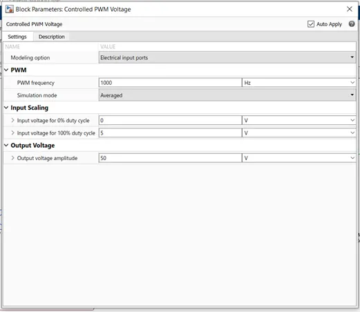
2) The PWM technique will check the reference value. If reference value is high it will take 1 & if it is low it will take as 0 & accordingly it will adjust the duty cycle & the voltage. Here also simulation mode is selected as average to have fast response. Rest values are set to be as default values.
3) Now as the current is not be sensed by the battery input as it is physical signal, a current sensor is used in between H-bridge & a DC motor in order to have a physical current signal.
4) The controlled voltage source is used to have a specified voltage at its output. The acceleration & deceleration command input from longitudinal driver is fed to the controlled voltage source block.
5) While modelling with simscape it is necessary to have solver configuration block connected to a reference which handles the simscape equations.
Battery Subsystem:

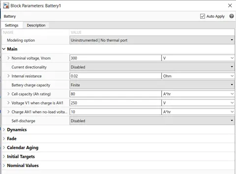
1) A simple battery is used for an EV vehicle to run which is connected to a controlled current source to have a specified current. Nominal voltage of battery is assumed to be 300 V & its Ah rating is assumed to be 80
2)Further the SOC calculation is been design. The essential process to calculate the SOC is by subtracting the charge from the rated capacity of the battery. The current is integrated w.r.t. time using integrator block to get the charge in coulumbs & further this coulumb value is modified into Ampere hours. This value is now subtracted from the charging capacity of the battery. The remaining charge is now converted into percentage value of the charging capacity of the battery.
Driver Controller & Drive cycle:
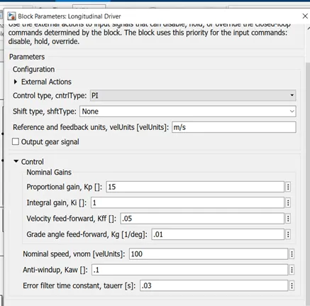
1) The longitudinal driver block is used to have the driver control. It represents the driver input As the longitudinal driver output has physical signal & it can't be sensed by the motor as it has electrical signals, so in order to convert the mechanical signal to electrical signal we have taken the controlled voltage source block. The acceleration is connected to the control PWM & the deceleration terminal is connected to the braking port of the H-bridge which is further connected to the DC motor. The reference velocity is the drive cycle which we have chosen & the feedback velocity is the vehicle velocity i.e. the actual velocity. As we are not considering the gradient, so it has been selected as '0' . The control type is selected as 'PI' control & rest are set as default.
2) We have taken three different drive cycles & to choose any of the drive cycle, multiport switch block is used which takes the input of any one of the drive cycle by giving the constant value to which the drive is connected accordingly that drive cycle will be selected.
3) The distance is found out in km/hr by integratrating the speed w.r.t. time & dividing it by 3600.
4) Scope is connected to the different ports to see the results.
5) The simulation is run for a time period of 2474 seconds
3) RESULTS:
1)Drive cycle result:
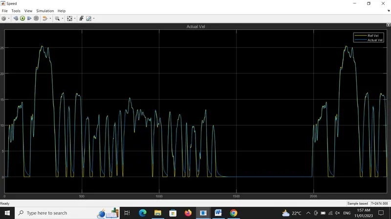
The yellow is the reference drive cycle & blue is the actual velocity. The actual velocity is trying to go with the reference one. In the acceleration both are almost overlapping each other while in deceleration we can find some delay in both the velocity.
2) Distance result:
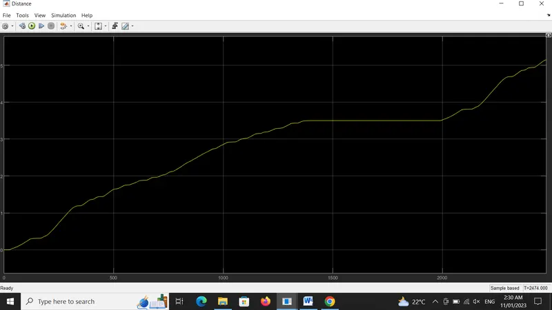
From the graph & from the display block we found that the distance is 5.148 km/hr & thus we can calculate the average speed of the vehicle.
Speed = distance / Time = (5.148 / 2474) * 3600 = 7.49 km/hr
So the average speed is coming out to be 7.49 km/hr.
3) Acceleration & Deceleration result:
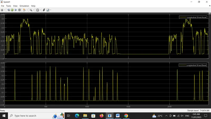
This graph shows the driver controller output where the driver is controlling the vehicle by giving the acceleration & deceleration command.
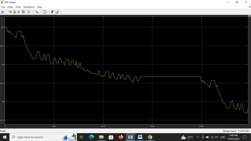
4) SOC result:
This graph shows the percentage of SOC of a vehicle battery. It shows that the battery gets depleted from 100 % to 97.82 %. As we have enable the regenerative braking option we can see that the battery is getting charged in the braking mode.
4) CONCLUSION:
1) Thus we have modeled a EV car design in simulink & verify all results succesfully using different mechanical & electrical blocks.
2) We have modeled by taking simple transmission system, simple permanent type DC motor & a converter block & thus by assuming some of the parameters values we got the results.
3) From the result we have found that a vehicle battery discharged by 2.18 % of its full capacity to cover a distance of 5.14 km/hr.