Final Project: Electric Rickshaw modelling
Question:
Create a detailed MATLAB model of an electric rickshaw (three-wheel passenger vehicle) as per the details below:
Rear wheels driven by PM brushed type motor
Assume efficiency points of motor controller and motor
Make an excel sheet of all input and assumed data
Results: For any three standard driving cycles show energy consumption, the temperature rise of motor and controller for 100 km constant speed driving at 45 mph.
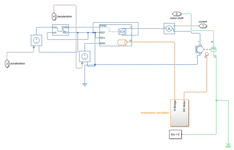
Circuit:
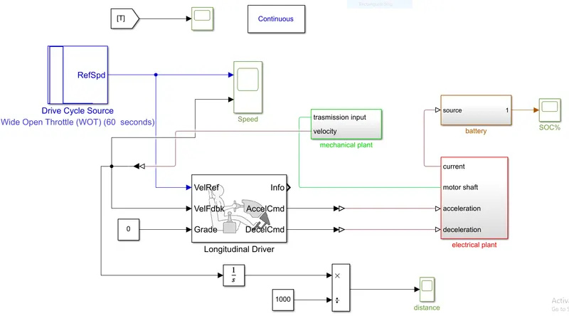
The Longitudinal Driver block implements a longitudinal speed-tracking controller. Based on reference and feedback velocities, the block generates normalized acceleration and braking commands that can vary from 0 through 1.
DC motor Converts input electrical energy into mechanical motion. Current Sensor. Converts the electrical current that drives the motor into a measurable physical signal proportional to the current. DC Voltage Source.
The H-Bridge block represents an H-bridge motor driver. If the input signal has a value greater than the Enable threshold voltage parameter value, the H-Bridge block output is on and has a value equal to the value of the Output voltage amplitude parameter.
The Drive Cycle Source block generates a standard or user-specified longitudinal drive cycle. The block output is the specified vehicle longitudinal speed, which you can use to Study, tune, and optimize vehicle control, system performance, and system robustness over multiple drive cycles.
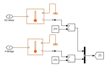
The Temperature Sensor block represents an ideal temperature sensor, that is, a device that determines the temperature differential measured between two points without drawing any heat. Connections A and B are thermal conserving ports that connect to the two points where the temperature is being monitored.
No code generation occurs for a Rate Transition block with a NoOp label. To prevent a block from being reduced when block reduction is on, add a test point to the block output (see Configure Signals as Test Points in the Simulink documentation).
The PWM Generator block generates pulses for carrier-based pulse width modulation (PWM) converters using a two-level topology.
The Controlled Voltage Source block converts a Simulink input signal into an equivalent voltage source. The generated voltage is driven by the input signal of the block. You can initialize the Controlled Voltage Source block with a specific AC or DC voltage.
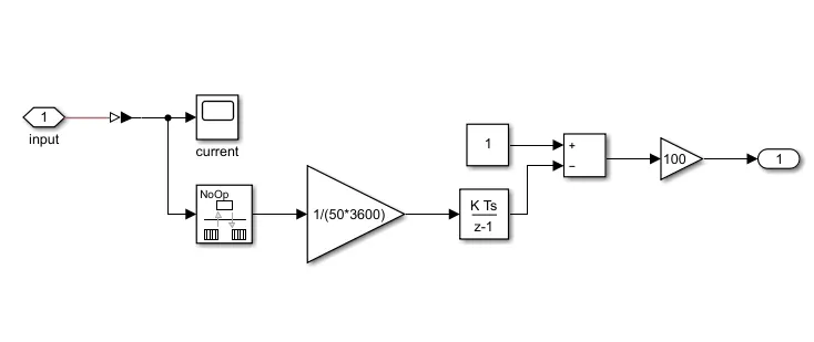
Energy block:
Mechanical block:
Temperature block:
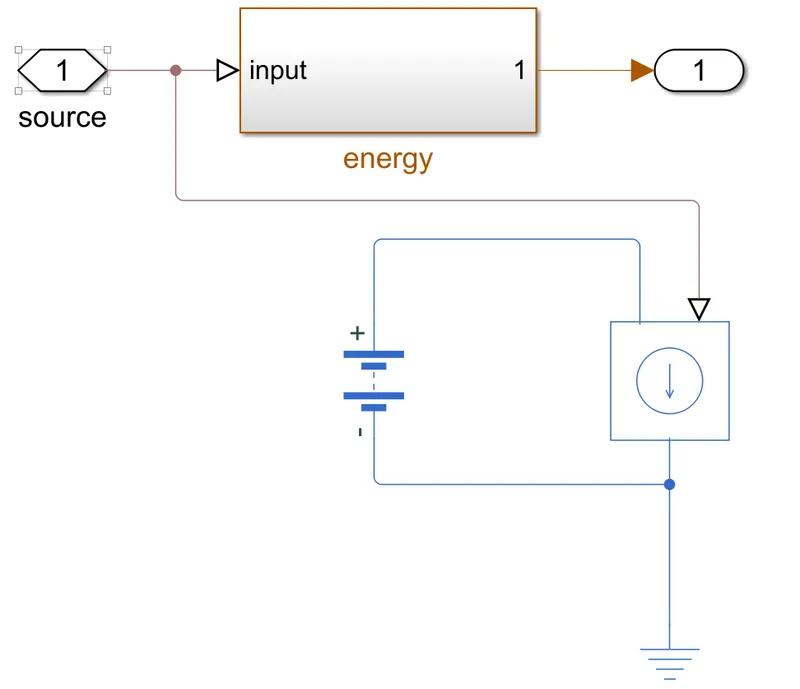
Battery block:
Electrical block:
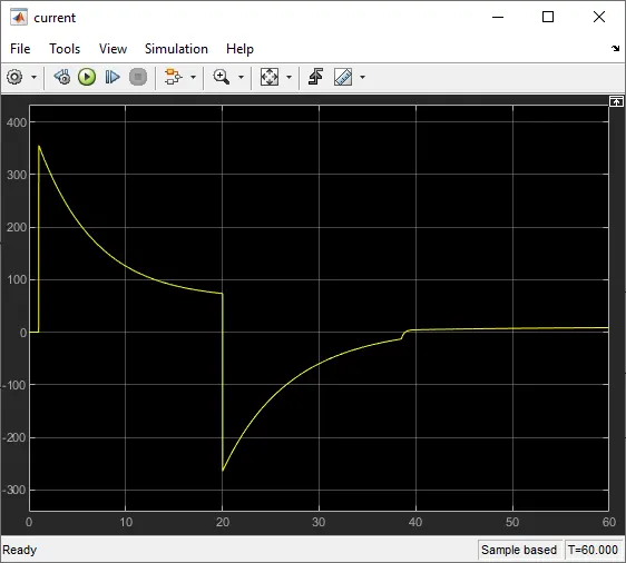
Output:
Current:
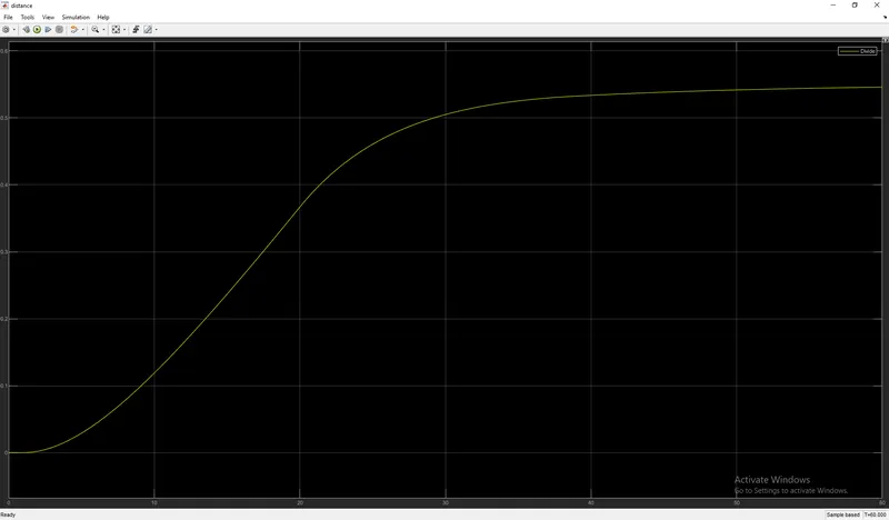
Distance:
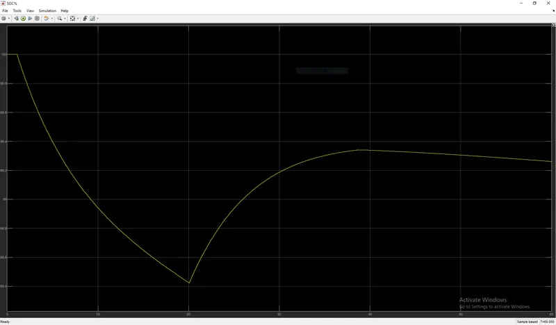
Soc:
Speed:
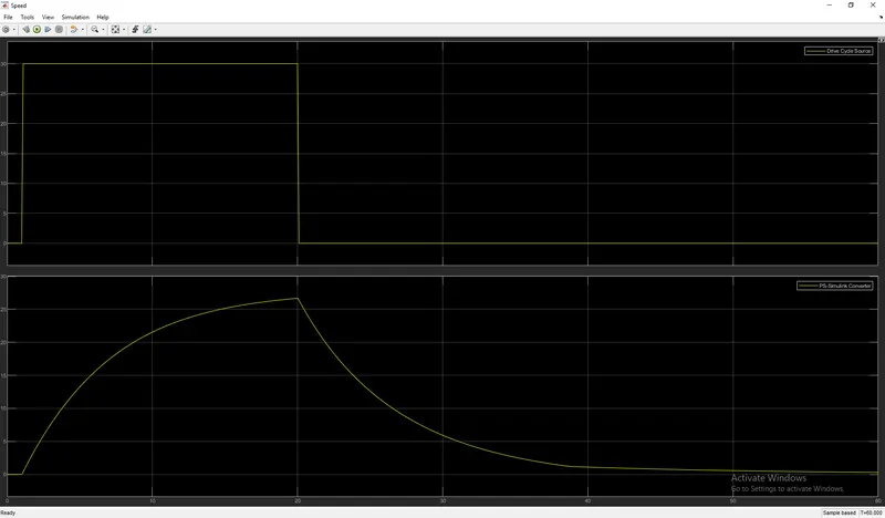
Explanation:
- The Drive cycle of WOT is been taken as the input.
- The feedback is been taken from the velocity of the mechanical plant.
- The grade value is been taken as 0.
- The feedback value is been differentiated and divided with the 1000 and get the distance that is been traveled.
- The acceleration and deceleration are been given to the electrical plant and the motor shaft is been taken as the input to the mechanical plant.
- The current is been taken s a source for the battery. and the output is been scoped as SOC.
- The mechanical plant has the gear, inertia, and the vehicle body connected with the wheels, and the velocity is been given out.
- In the electrical plant, the acceleration and deceleration is been taken as the reference after the connection with the source.
- The acceleration is connected with the reference and the PWM and REF are taken in the H-bridge.
- The PWM signal is been connected with the ampere where the current is been taken out as a reference and the current is been taken in the DC motor.
- The thermal system is been taken input from the H-bridge and the DC motor and the values are been scoped.
- This whole circuit tells the usage of the battery with the dc motor, that how much is the distance the vehicle can travel with the battery that is been present and all those values are been noted.